EP4488204A2 - Surface de contact de courroie destinée à un système de transporteur - Google Patents
Surface de contact de courroie destinée à un système de transporteur Download PDFInfo
- Publication number
- EP4488204A2 EP4488204A2 EP24191754.1A EP24191754A EP4488204A2 EP 4488204 A2 EP4488204 A2 EP 4488204A2 EP 24191754 A EP24191754 A EP 24191754A EP 4488204 A2 EP4488204 A2 EP 4488204A2
- Authority
- EP
- European Patent Office
- Prior art keywords
- endless belt
- belt
- rinsing
- rinsing system
- aperture
- Prior art date
- Legal status (The legal status is an assumption and is not a legal conclusion. Google has not performed a legal analysis and makes no representation as to the accuracy of the status listed.)
- Withdrawn
Links
Images










Classifications
-
- B—PERFORMING OPERATIONS; TRANSPORTING
- B60—VEHICLES IN GENERAL
- B60S—SERVICING, CLEANING, REPAIRING, SUPPORTING, LIFTING, OR MANOEUVRING OF VEHICLES, NOT OTHERWISE PROVIDED FOR
- B60S3/00—Vehicle cleaning apparatus not integral with vehicles
- B60S3/004—Conveyors for vehicle cleaning apparatus
-
- B—PERFORMING OPERATIONS; TRANSPORTING
- B65—CONVEYING; PACKING; STORING; HANDLING THIN OR FILAMENTARY MATERIAL
- B65G—TRANSPORT OR STORAGE DEVICES, e.g. CONVEYORS FOR LOADING OR TIPPING, SHOP CONVEYOR SYSTEMS OR PNEUMATIC TUBE CONVEYORS
- B65G15/00—Conveyors having endless load-conveying surfaces, i.e. belts and like continuous members, to which tractive effort is transmitted by means other than endless driving elements of similar configuration
- B65G15/10—Conveyors having endless load-conveying surfaces, i.e. belts and like continuous members, to which tractive effort is transmitted by means other than endless driving elements of similar configuration comprising two or more co-operating endless surfaces with parallel longitudinal axes, or a multiplicity of parallel elements, e.g. ropes defining an endless surface
- B65G15/12—Conveyors having endless load-conveying surfaces, i.e. belts and like continuous members, to which tractive effort is transmitted by means other than endless driving elements of similar configuration comprising two or more co-operating endless surfaces with parallel longitudinal axes, or a multiplicity of parallel elements, e.g. ropes defining an endless surface with two or more endless belts
-
- B—PERFORMING OPERATIONS; TRANSPORTING
- B65—CONVEYING; PACKING; STORING; HANDLING THIN OR FILAMENTARY MATERIAL
- B65G—TRANSPORT OR STORAGE DEVICES, e.g. CONVEYORS FOR LOADING OR TIPPING, SHOP CONVEYOR SYSTEMS OR PNEUMATIC TUBE CONVEYORS
- B65G15/00—Conveyors having endless load-conveying surfaces, i.e. belts and like continuous members, to which tractive effort is transmitted by means other than endless driving elements of similar configuration
- B65G15/22—Conveyors having endless load-conveying surfaces, i.e. belts and like continuous members, to which tractive effort is transmitted by means other than endless driving elements of similar configuration comprising a series of co-operating units
-
- B—PERFORMING OPERATIONS; TRANSPORTING
- B65—CONVEYING; PACKING; STORING; HANDLING THIN OR FILAMENTARY MATERIAL
- B65G—TRANSPORT OR STORAGE DEVICES, e.g. CONVEYORS FOR LOADING OR TIPPING, SHOP CONVEYOR SYSTEMS OR PNEUMATIC TUBE CONVEYORS
- B65G15/00—Conveyors having endless load-conveying surfaces, i.e. belts and like continuous members, to which tractive effort is transmitted by means other than endless driving elements of similar configuration
- B65G15/60—Arrangements for supporting or guiding belts, e.g. by fluid jets
- B65G15/62—Guides for sliding belts
-
- B—PERFORMING OPERATIONS; TRANSPORTING
- B65—CONVEYING; PACKING; STORING; HANDLING THIN OR FILAMENTARY MATERIAL
- B65G—TRANSPORT OR STORAGE DEVICES, e.g. CONVEYORS FOR LOADING OR TIPPING, SHOP CONVEYOR SYSTEMS OR PNEUMATIC TUBE CONVEYORS
- B65G45/00—Lubricating, cleaning, or clearing devices
- B65G45/10—Cleaning devices
- B65G45/22—Cleaning devices comprising fluid applying means
-
- B—PERFORMING OPERATIONS; TRANSPORTING
- B65—CONVEYING; PACKING; STORING; HANDLING THIN OR FILAMENTARY MATERIAL
- B65G—TRANSPORT OR STORAGE DEVICES, e.g. CONVEYORS FOR LOADING OR TIPPING, SHOP CONVEYOR SYSTEMS OR PNEUMATIC TUBE CONVEYORS
- B65G2207/00—Indexing codes relating to constructional details, configuration and additional features of a handling device, e.g. Conveyors
- B65G2207/48—Wear protection or indication features
-
- B—PERFORMING OPERATIONS; TRANSPORTING
- B65—CONVEYING; PACKING; STORING; HANDLING THIN OR FILAMENTARY MATERIAL
- B65G—TRANSPORT OR STORAGE DEVICES, e.g. CONVEYORS FOR LOADING OR TIPPING, SHOP CONVEYOR SYSTEMS OR PNEUMATIC TUBE CONVEYORS
- B65G2812/00—Indexing codes relating to the kind or type of conveyors
- B65G2812/02—Belt or chain conveyors
- B65G2812/02009—Common features for belt or chain conveyors
- B65G2812/02019—Supporting or guiding frames
-
- B—PERFORMING OPERATIONS; TRANSPORTING
- B65—CONVEYING; PACKING; STORING; HANDLING THIN OR FILAMENTARY MATERIAL
- B65G—TRANSPORT OR STORAGE DEVICES, e.g. CONVEYORS FOR LOADING OR TIPPING, SHOP CONVEYOR SYSTEMS OR PNEUMATIC TUBE CONVEYORS
- B65G2812/00—Indexing codes relating to the kind or type of conveyors
- B65G2812/02—Belt or chain conveyors
- B65G2812/02009—Common features for belt or chain conveyors
- B65G2812/02108—Protection means
Definitions
- the present disclosure relates to the field of conveyor systems for transporting wheeled structures, and in particular to a conveyor system suitable for use in an automatic vehicle wash station.
- Conveyor systems have long been used to assist in the transport of materials from one location to another, in particular with respect to heavy and cumbersome items.
- the use of conveyor systems in assembly lines is well documented, with perhaps Henry Ford being the most famous proponent of the technology of the 20 th century.
- a debris deflector 98 also provided between the upper transport portion 42 and the lower return portion 44 of the endless belt 36, and in particular between the support deck 84 and the lower return portion 44 is a debris deflector 98.
- the debris deflector 98 provides a barrier to protect the lower return portion 44 from debris falling from the support deck 84, in particular where the support deck 84 is provided in the form of the modular grid panels.
- the debris deflector 98 is generally mounted on an angle directed downwardly towards the longitudinal centerline of the service line.
- the debris deflector 98 may be mounted on dedicated brackets, or may be mounted on the guide hangers 90 and 92 used for supporting the guide members 66 (as shown).
- the debris deflector 98 is generally configured to provide a contiguous barrier between adjacent cross-members, so as to maximize the protection from falling debris.
- the debris deflector 98 may be provided in the form of multiple panels arranged and fastened in side-by-side relationship to one another.
- the arrangement of the support deck 84, the debris deflector 98 and the longitudinally-spaced cross-members 68 define a partial enclosure in the region between the upper transport portion 42 and the lower return portion 44 of the endless belt 36.
- at least a portion of the conveyor system 20 may include a heater in these partial enclosures between adjacent cross-members 68.
- the conveyor system 20 provides a heater 100 positioned between the support deck 84 and the debris deflector 98, extending in the longitudinal direction across one or more of the partial enclosures delimited longitudinally between adjacent cross members 68.
- the partial enclosures containing the heater 100 provide a region of higher heat concentration relative to other areas within the trench 40, in particular the area below the debris deflector 98.
- the support deck 84, the endless belt 36 supported thereon, and the plurality of wear plates 88 positioned therebetween receive heat from the region of higher heat concentration, thereby reducing the likelihood of a freeze event in the conveyor system 20. It will be appreciated that freeze events in conveyor systems can result in extensive damage to the endless belt 36 and/or drive module 56.
- the heater 100 may take on a variety of forms.
- the heater 100 may be configured as a convective heater, such as a convective tube heater including both smooth and finned-tube varieties.
- a convective tube heater will generally be part of a fluid circuit having an electric or gas-fired heater module to deliver a heated fluid therein.
- the heater 100 may also be configured as a radiant heater such as a gas-fired radiant tube heater, or a resistive electrical heating element.
- the debris deflector 98 may be formed from any suitable material including but not limited to metal (e.g., stainless steel, galvanized steel, aluminum, etc.), thermoplastics (e.g., polypropylene, polyethylene, etc.) and composites.
- the debris deflector 98 may be adapted with at least a selected level of thermal reflectivity.
- the thermal reflectivity may be achieved by constructing the debris deflector 98 in the form of a radiant barrier.
- a radiant barrier may be separately formed and applied to the debris deflector 98, for example in the form of a thin radiant barrier sheet attached thereto.
- Radiant barriers are typically highly reflective materials (e.g., aluminum or polished stainless steel foil) applied to a substrate.
- Exemplary substrates may include kraft paper, oriented strand board, plastic films and plywood.
- the substrate may be of metal or thermoplastic construction.
- Exemplary thermoplastic substrates may include polypropylene or polyethylene foam core.
- the material applied to the substrate should exhibit an emittance of less than 0.25, as measured by ASTM C1371.
- low-emittance coatings such as metal oxide may be used on a suitable substrate.
- the side of the debris deflector 98, or separately formed sheet, facing the support deck 84 is the side adapted to receive the highly reflective material.
- the highly reflective material, and thus the effective side of the radiant barrier is intended to face the region of higher heat concentration between the debris deflector 98 and the support deck 84.
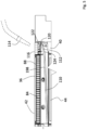
- the debris deflector 198 includes a debris portion 110 that is positioned under the support deck 84, and a water collection portion 112 that extends outwardly therefrom, towards a respective side wall of the trench 40.
- the water collection portion 112 is intended to facilitate cleaning of the debris portion 110 of the debris deflector 198, without the need for substantial disassembly and associated downtime of the conveyor system.
- a sprayer or suitable wash nozzle 114 may be positioned as shown to deliver a stream of water directly upon the water collection portion 112 of the debris deflector 198, promoting a wash effect to remove accumulated debris from the debris portion 110.
- Access to the water collection portion 112 may be achieved by removing side panels 116, or where the side panels 116 are provided in the form of fiberglass or thermoplastic grating, wash water may be delivered directly therethrough.
- the use of grates for the side panels 116 will also permit a greater volume of wash and rinse water from the wash tunnel to be captured by the water collection portion 112, enhancing the cleaning effect of the debris deflector 198 during normal wash tunnel usage.
- the water collection portion 112 of the debris deflector 198 is generally arranged at an angle relative to the debris portion 110, with its terminal lateral edge 120 being positioned proximal the underside 122 of the side panel 116.
- the debris deflector 198 is provided with a curved transition 124 between the water collection portion 112 and the debris portion 110 to deflect the impingement of rinse water, with reduced turbulence, therein resulting in an effective flushing of debris from the debris portion 110 of the debris deflector 198.
- the debris deflector 98, 198 may be formed of stamped or formed stainless steel, or galvanized steel to provide a rust-inhibiting effect.
- the debris deflectors 98, 198 may be formed of a thermoplastic material, for example a polyolefin, a low or high-density polyethylene, polyvinyl chloride, or an acrylonitrile butadiene styrene (ABS), and may include suitable fillers or additives to achieve the desired performance characteristics.
- suitable materials will exhibit resistance to wear, corrosion and pitting, as well as low moisture absorption and low reactivity to chemicals.
- the debris deflector 98, 198 may be formed of polypropylene or polyethylene, and may include glass fibers to improve impact performance at low temperature.
- the debris deflector 98, 198 may be formed via any suitable molding process, including but not limited to vacuum forming, compression molding and thermoforming.
- a thermoplastic debris deflector may incorporate one or more structural ribs 126 (as seen in Fig. 6 ). The structural ribs 126 provide additional rigidity to the debris deflector 98, 198, and establish sluice-like channel-ways 128 that direct water flow, enhancing the wash effect.
- the upper transport portion 42 of the endless belt 36 moves in tension from the idler end 48 towards the drive end 46 by drive member 56, while the lower return portion 44 moves in a slackened state from the drive end 46 towards the idler end 48.
- the lower return portion 44 of the endless belt 36 may be subject to greater lateral movement, having the potential to create belt tracking and alignment issues. This is particularly evident at the idler end 48 where the axially elongated roller 52 is not provided with engagement teeth as found on the opposing drive member 58 at the drive end 46.
- Misalignment and poor tracking of the endless belt 36 can cause excessive wear on the conveyor mechanism, necessitating increased maintenance and associated downtime. Issues of misalignment of the endless belt 36 can increase upon aging of the endless belt 36, generally due to belt stretch. Accordingly, in an alternative embodiment, a least one pair of lateral guide rollers are incorporated into the conveyor system 20.
- each lateral guide 130a, 130b is provided with at least one roller (first roller 132) presenting a first roller surface 134 positioned to engage a respective lateral edge of the lower return portion 44 of the endless belt 36.
- each lateral guide 130a, 130b is presented as having two stacked rollers, that is the first roller 132 and a second roller 136.
- the addition of the second roller 136 provides a second roller surface 138 positioned to engage the endless belt 36 in a more slackened state.
- the height of the first roller 132 can be large enough to span the expected range of the path of the endless belt 36, thereby mitigating the need for two or more rollers.
- a newly installed endless belt 36 having very little operational time will exhibit less slack, and therein align to the first roller surface 134 of the first roller 132, as shown in Fig. 2c .
- the endless belt 36 With usage and ageing of the endless belt, additional slack arising from stretch in the endless belt 36 may cause the endless belt 36 to displace downwardly, with the lateral edges of the lower return portion 44 aligning with the second roller surface 138 of the second roller 136. Further, changes in ambient temperature can cause the lengthening and shortening of the endless belt 36, causing it to align with the first roller surface 134 or the second roller surface 138. Accordingly, the lateral guides 130a, 130b are configured to provide lateral support over the useable lifespan of the endless roller 36.
- the lateral guides 130a, 130b generally include the at least one roller (first and second rollers 132, 136 as presented herein) mounted upon a bracket 140, as best seen in Fig. 8 .
- the bracket 140 provides a mount portion 142 that is fastened to the conveyor frame 54, and a roller support portion 144 that receives the at least one roller (rollers 132, 136 in the embodiment shown).
- the rollers may be any suitable material, including but not limited to polymeric or rubber materials (i.e., rubber-tired caster wheels), and may include a suitable bushing or bearing to facilitate rotation about an axis A.
- the bearing may be a sealed bearing to prevent the ingress and fouling of the bearing due to contaminated water and debris.
- each cross-member 68 may be adapted to mount directly upon the opposing surfaces 70 and 72, for example by welded attachment to an anchorage bar 150 embedded in the concrete at the upper longitudinal edge the trench 40. While effective, direct attachment can be labor intensive as supporting the heavy cross member 68 during attachment can be difficult. Accordingly, in an alternative embodiment, the plurality of cross members 68 are attached on opposing ends to a respective cross-member mount bracket 152, as shown in Fig. 9 .
- the cross-member mount bracket 152 includes an anchorage portion 154 configured for attachment to the anchorage bar 150, and a cross-member portion 156 configured to receive and support the cross-member 68.
- each side of the trench 40 includes along the upper longitudinal edge 158 the anchorage bar 150, generally provided in the form of angle iron embedded in the concrete.
- a mount bracket 152 is welded to the anchorage bar 150.
- the mount bracket 152 is easier to locate in relation to a desired vertical elevation on the anchorage bar 150, and may be tack-welded in place prior to permanent attachment to enable alignment and level verification over the longitudinal length of the trench prior to final welding.
- the cross-members are attached at opposing ends to respective cooperating mount brackets. Attachment may be achieved using suitable fasteners, for example bolts 160.
- the complementary profile is provided in the form of a chevron aligned to the direction of travel of the vehicle through the wash tunnel. At least one of the leading and trailing edges 166 and 168 of the wear plates 88 may be chamfered to reduce the likelihood of wear upon the endless belt.
- the wear plates 88 are made from a material that is at least partially thermoplastic, and, in particular, at least partially polyethylene, such as an ultra-high-molecular-weight polyethylene (“UHMWPE”), which is also known as high-modulus polyethylene (“HMPE”).
- UHMWPE is a thermoplastic polyethylene that has extremely long chains. The longer chains serve to transfer load more effectively to the polymer framework by reinforcing intermolecular interactions. Further, UHMWPE has low moisture absorption, a very low coefficient of friction, a high strength, and is highly resistant to abrasion as a result of the longer chains, especially in comparison to carbon steel. Further, UHMWPE is very resistant to corrosion.
- Some particular exemplary materials that can be used to manufacture the wear plates are virgin UHMWPE such as available from Röchling Engineering Plastics and the Garland Manufacturing Company, reprocessed UHMWPE such as available from Röchling Engineering Plastics, glass filled UHMWPE such as available from Quadrant Plastic Composites Inc., ceramic filled UHMWPE such as available from Polymer Industries Inc. and Quadrant Plastic Composites Inc., and cross-linked UHMWPE such as available from Röchling Engineering Plastics and Polymer Industries Inc.
- the wear plates can be made from a material that is at least partially high-density polyethylene ("HDPE"). HDPE is also suitable for use for construction of the wear plates 88.
- a proprietary polyethylene, Polystone TM sold by Röchling Engineering Plastics can be used to manufacture the wear plates.
- the material of the wear plates 88 can be selected it has a hardness H WP that is lesser than the hardness H BS of the plastic belt segments in some scenarios.
- the costs for the manufacturing of wear plates form these materials ranges from 63% to over 200% of the price using stainless steel in some cases, based on the current prices of stainless steel and these thermoplastics.
- suitable thickness ranges are in the 3/16 inch to 3/8 inch range (5-10 mm) in some scenarios.
- the belt contact surface i.e., the wear plates 88
- the wear plates 88 the belt contact surface from a softer material than stainless steel that is traditionally used, and by rinsing away debris from the interface between the endless belts 36a, 36b and the support deck, the lifetime of the endless belts 36a, 36b can be increased as a result of the lower wear from contact with the wear plates 88.
- thermoplastics such as UHMWPE and HDPE have been found to be suitable due to their possession of certain characteristics. These materials provide a sufficiently low coefficient of friction, and are sufficiently resistant to abrasion.
- the wear plates 88 are inexpensive to replace relative to the replacement cost of the endless belts 36a, 36b.
- the replacement cost of an endless belt 36a, 36b can be high as there is a significant amount of manual labor in disassembling the belt segments to be replaced.
- Wear plates made from a material that is substantially UHMW have been found to have a service lifetime that ranges from 11% to 200% of the durability of wear plates made from stainless steel.
- thermoplastics are generally have a hardness H WP that is lesser than the hardness H BS of the belt segments of the endless belts 36a, 36b.
- H WP hardness of the belt segments of the endless belts 36a, 36b.
- the wear plates 88 are designed to improve the lifetime of the endless belt 36 by sacrificing the lifetime of the wear plates 88.
- Polyethylenes and other thermoplastics are subject to thermal expansion and contraction. In the car wash environment, the range of temperatures that the wear plates 88 are subject to is significant.
- the wear plates 88 have a longitudinal length of approximately 44 inches and have been found to expand and contract +/- 0.2 inches over a typical operational ambient temperature range. In order to compensate for these expansions and contractions, expansion gaps between the leading and trailing edges 166 and 168 of the wear plates 88 of 0.2 inches or greater are provided.
- Each wear plate 88 is provided with a plurality of debris slots 170 that permit the evacuation of debris therethrough, so as to reduce the accumulation of debris between the endless belt and the wear plates 88.
- Each debris slot 170 includes a first slot end 172 and a second slot end 174, and is provided with a width of 10 mm, although widths of between 8 to 25 mm may be implemented.
- Each debris slot 170 may be linear (i.e., straight) and may be arranged at an angle ⁇ relative a longitudinal centerline L of the wear plate 88. As shown, the debris slot 170 is outwardly angled from the longitudinal centerline L in the direction of the first slot end 172 towards the second slot end 174.
- each debris slot 170 is 35° relative to the longitudinal centerline L of the wear plate 88, although angles between 25° to 45° may be implemented.
- angle selection is based on observed belt wear. It has been determined that angles within this range, and in particular at 35° relative to the longitudinal centerline L of the wear plate 88 result in the least amount of endless belt wear during use, therein increasing the usable lifespan of the endless belt and wear plates.
- each debris slot 170 can be provided with an inwardly sloped bevel 176, as shown in Fig. 12a . It has been determined that maximum wear of the endless belt occurs where the endless belt passes over a sharp edge perpendicular to the direction of belt travel. Accordingly, with the first and second slot ends 172 and 174 having the inwardly sloped bevel 176, in particular at the second slot end 174, the extent of belt wear is reduced, particularly when the wear plates are constructed of stainless steel. Between the first and second slot ends 172 and 174 of the debris slot 170, the opposing edges 178a and 178b remain unbeveled, that is they remain as sharp edges, as shown in Fig. 12b .
- the extent of belt wear is minimal. Moreover, by maintaining these edges sharp as shown, they provide a stripping action to remove debris from the underside of the endless belt, without excessive wear thereto.
- first and second slot ends 172 and 174 are shown as being beveled, in some embodiments, only one of the first and second slot ends 172 and 174 is beveled. In an alternative embodiment, only the second slot end 174 is beveled.
- thermoplastics that are softer than stainless steel, have a low coefficient of friction, and/or a high resistance to abrasion in constructing the wear plates, it has been found that the beveling of the debris slots 170 as shown in Figs. 12a and 12b can be omitted without materially increasing wear on the endless belt 36.
- the beveling of the debris slots 170 adds to the manufacturing costs of the wear plates 88 and, thus, the ability to omit this feature without materially impacting the lifetime of the endless belt 36 is another benefit to the use of thermoplastics in the construction of the wear plates 88.
- each wear plate 88 provides 8 debris slots 170, generally presented in two rows of 4 arranged across the wear plate 88. Within each row, the 4 debris slots are arranged in two paired sets of debris slots, with the two paired sets of debris slots being longitudinally offset relative to one another. The arrangement of the debris slots 170 is such that the leading and trailing ends 172 and 174 of successive debris slots 170 align, so as to reduce the number of locations having increased potential for belt wear. As shown, alignment between successive debris slots occurs along longitudinal centerline L, as well as alignment line AL A and alignment line AL B .
- each wear plate 88 is shown as having 8 debris slots 170, in other embodiments, the number of debris slots 170 may be fewer or greater, depending on the extend of debris removal required. While the leading and trailing ends 172 and 174 of all debris slots 170 may be machined with the aforementioned inwardly sloped bevel, in some embodiments, only the debris slots 170 arranged proximal the longitudinal centerline L of the wear plate 88 may be beveled. In other preferred embodiments, the debris slots 170 are not beveled.
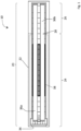
- the inner and outer support rails 78a, 80a provide respective guide hangers 90, 92 that support the guide member 66 in a transverse direction relative to the longitudinal direction of the service line 10.
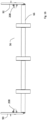
- Guide member 66 includes a plurality of rollers 94 (94a, 94b, 94c) mounted on a stationary shaft 180 supported at a first end 182 by guide hanger 90 (not shown for clarity), and at a second end 184 by guide hanger 92.
- the stationary shaft 180 is a stainless steel shaft, with at least one of the first and second ends 182 and 184 being configured with a suitable keyed interface with respective guide hangers 90 and 92 to prevent rotation of the stationary shaft 180 relative thereto.
- Each roller 94 (94a, 94b, 94c) provided is rotatably mounted on the stationary shaft 180 using a suitable bushing or bearing interface therebetween.
- a low friction thermoplastic bushing 186 is used.
- Suitable thermoplastics include, but are not limited to acetal (i.e., Delrin TM ) and UHMWPE. As shown in Fig.
- the thermoplastic bushing 186 is configured with a central portion 188 that engages a shaft aperture 190 of roller 94, as well as a first bushing extension 192 and a second bushing extension 194.
- the central portion 188 of the thermoplastic bushing 186 is press-fit or otherwise mounted in the shaft aperture 190, so as to rotate with the roller 94. Accordingly, upon rotation of the roller 94 during use, the thermoplastic bushing 186 rotates upon the stationary shaft 180, with the thermoplastic bushing 186 providing a low friction interface therebetween.
- the guide member 66 additionally includes a series of protective sleeves that cover the stationary shaft 180 and serve to protect the interface between the stationary shaft 180 and the thermoplastic bushings 186 from debris and contaminated water.
- a first and second outer sleeve 196 and 198 is provided between respective guide hangers 90 and 92 and the outer rollers 94a and 94b.
- a first and a second inner sleeve 200 and 202 are provided between the respective outer rollers 94a and 94b and the middle roller 94c. It will be appreciated that the inner and outer sleeves also serve as spacers to maintain the rollers 94 in the desired position on the stationary shaft 180.
- the first and second outer sleeves 196 and 198 are configured to remain stationary during use. Accordingly, at each end 182 and 184 of the stationary shaft 180, a fixed non-rotatable interface is established between the stationary shaft 180 and the first and second outer sleeves 196 and 198 associated therewith. Having regard to Fig. 15 detailing the arrangement at the first end 182, a fixed bushing 204 is provided between the first outer sleeve 196 and the stationary shaft 180. The interface between the stationary shaft 180 and the fixed bushing 204, in particular the outside diameter of the stationary shaft 180 relative to the inside diameter of the fixed bushing 204 is sized to establish an interference fit therebetween. As such, a fixed non-rotatable relationship is established between the stationary shaft 180 and the fixed bushing 204.
- the interface between the fixed bushing 204 and the first outer sleeve 196, in particular the outside diameter of the fixed bushing 204 relative to the inside diameter of the first outer sleeve 196 is sized to establish an interference therebetween.
- a fixed non-rotatable relationship is established between the fixed bushing 204 and the first outer sleeve 196.
- the first outer sleeve 196, as well as the second out sleeve 198 which is mounted in an identical manner relative to the second end 184 remain fixed in relation to the stationary shaft 180.
- first outer sleeve 196 On the opposing end of the first outer sleeve 196, that is where it engages the first bushing extension 192 of the thermoplastic bushing 186 at the roller 94a, the inside diameter of the first outer sleeve 196 relative to the outside diameter of the first bushing extension 192 is sized to establish a slip-fit therebetween. As such, first outer sleeve 196 remains fixed while the thermoplastic bushing 186 is permitted to rotate relative thereto. It will be appreciated that the opposing end of the second outer sleeve 198 is similarly configured relative to the thermoplastic bushing 186 at the roller 94b, so as to achieve the same slip-it relationship therebetween.
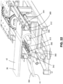
- the rinsing system outlets 310 are positioned below the wear plates 308 and are positioned to eject the rinsing system liquid up through the rinsing system dirt pass-through aperture 306 into the belt 36.
- the rinsing system dirt pass-through aperture 306 has an elongate cross-sectional shape and is sized to permit the ejecta 312 (i.e., the rinsing system liquid ejected therefrom) to leave upwardly from the rinsing system dirt pass-through aperture 306, to hit the endless belt 36 and to fall through the rinsing system dirt pass-through aperture 306 after hitting the endless belt, bringing dirt with it, as shown in Fig. 20 .
- the outlet 310 is well below the wear plate 308 and so the ejecta 312 pass upwardly through the rinsing system dirt pass-through aperture 306, hit the belt 36 and then fall back down through the aperture 306.
- the support deck (e.g., the wear plates 88 and 308) includes a plurality of dirt pass-through apertures as described above. These apertures will permit the dirt and liquid from the flooding system to fall through, thereby removing dirt from the interface between the belt 36 and the wear plates 88 and 308.
- the flooding system 400 may include a plurality of belt flooding members 404 positioned at selected distances longitudinally from one another, such as, for example, about every 20 to 30 feet from one another.
- each belt flooding member 404 is positioned between gratings 412 that support the wear plate 88 or 308 and thus may act as a spacer between these gratings 412.
- the gratings 412 need not be gratings and may also be identified more broadly as wear plate support members 412.
- Figs. 26a to 26c show wear plates 500 in accordance with another embodiment.
- the wear plates 500 are similar in size and construction to wear plates 88 shown in Figs. 10 , 11 , 17a , and 17b .
- each of the wear plates 500 includes a leading edge 504 and a trailing edge 508, wherein the leading and trailing edges 504 and 508 are provided with complementary profiles to facilitate fit and alignment between adjacently positioned wear plates 500.
- the complementary profile is provided generally in the form of a chevron aligned to the direction of travel of the vehicle through the wash tunnel.
- At least one of the leading and trailing edges 504 and 508 of the wear plates 500 may be chamfered to reduce the likelihood of wear upon the endless belt.
- the wear plates 500 expand and contract with temperature changes. To allow for this expansion and contraction, the wear plates 500 are secured via fasteners inserted through fastener holes 522 that fit within slotted holes of the modular grid panels of the support deck. This arrangement allows a degree of freedom of movement (or, more to the point, expansion) of the wear plates 500. It can also be desirable to maintain the leading and trailing edges 504 and 508 in lateral alignment to avoid changes in the lateral profile of the belt contact surface (i.e., the wear plates 500) in the longitudinal direction that can serve to more quickly wear and/or damage the endless belt.
- the wear plates 500 have mating features inhibiting lateral shifting of the wear plates 500 relative to one another in the form of fingers 512 that extend longitudinally (i.e., generally along the direction of travel of the endless belt) forward from lateral ends of the leading edges 504, and corresponding finger recesses 516 that extend longitudinally from lateral ends of the trailing edges 508.
- the fingers 512 mate with the finger recesses of adjacent wear plates 500 to maintain the wear plates 500 in lateral alignment while the wear plates 500 expand to reduce an expansion gap 518 between the wear plates 500, and contract.
- the fingers can extend longitudinally from the trailing edge and mate with corresponding finger recesses of the leading edge of an adjacent wear plate.
- a finger and a recess can be located on opposite lateral ends of each leading and trailing edge and mate with the corresponding features of adjacent wear plates.
- Other types of mating features that inhibit lateral shifting of the wear plates will occur to those skilled in the art.
- the wear plates 500 also have debris slots 520 that permit the evacuation of debris therethrough, so as to reduce the accumulation of debris between the endless belt and the wear plates 500.
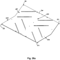
- FIGs. 27a and 27b show two variants of the design of the wear plates.
- a wear plate 600 shown in Fig. 27a has fingers 604 that extend longitudinally (i.e., generally along the direction of travel of the endless belt) forward from lateral ends of the leading edge 606, and corresponding finger recesses 608 that extend longitudinally from lateral ends of the trailing edge 610.
- the fingers 604 mate with the finger recesses of adjacent wear plates 600 to maintain the wear plates 600 in lateral alignment while the wear plates 600 expand to reduce an expansion gap between the wear plates 600, and contract.
- a set of four locating slots 612 are positioned two along each lateral side of the wear plate 600.
- the wear plate 600 has a pattern of debris slots 616 that differs from those shown in the previous figures. In particular, the debris slots 616 are wider and shorter, enabling ample drainage without significantly affecting the structural integrity of the wear plate 600. That is, there are no portions of the wear plate 600 that are connected to the remainder of the wear plate 600 only by narrow sections.
- a wear plate 620 shown in Fig. 27b has similar features to the wear plate 600 of Fig. 27a , but has different pattern of varying dimensioned debris slots.
- a first set of longitudinal debris slots 624 are generally rectangular with rounded corners, similar to the debris slots described and illustrated above, and are located centrally between the lateral sides 626 of the wear plate 620.
- a second set of peripheral debris slots 628 extend adjacent to the lateral sides 626 of the wear plate 620.
- Each of the peripheral debris slots 628 has a longitudinal portion 632 extending along a similar direction as the longitudinal debris slots 624, and a lateral portion 636 that deviates from the longitudinal portion 632 and extends along the travel direction dt of the belt.
- Fig. 28 shows locating features of a wear plate 700 and an edge guide 704 that assist with maintaining the correct alignment of the wear plates 700 while enabling them to expand and contract as a result of fluctuations in the operating temperature.
- the wear plates 700 have locating slots 708 along their lateral edges.
- the edge guide 704 is made of 14 gauge stainless steel that has a curved profile, enabling it to be deflected as the wear plates 700 are being positioned. Locating tabs 712 of the edge guide 704 mate with the locating slots 708 of the wear plates 700. The size of the locating tabs 712 and the locating slots 708 are selected to enable the wear plates 700 to expand and contract.
Landscapes
- Engineering & Computer Science (AREA)
- Mechanical Engineering (AREA)
- Chain Conveyers (AREA)
- Belt Conveyors (AREA)
- Structure Of Belt Conveyors (AREA)
Applications Claiming Priority (3)
| Application Number | Priority Date | Filing Date | Title |
|---|---|---|---|
| US201762598641P | 2017-12-14 | 2017-12-14 | |
| EP18887922.5A EP3724110B1 (fr) | 2017-12-14 | 2018-12-13 | Surface de contact de courroie destinée à un système de transporteur |
| PCT/CA2018/051594 WO2019113702A1 (fr) | 2017-12-14 | 2018-12-13 | Surface de contact de courroie destinée à un système de transporteur |
Related Parent Applications (1)
| Application Number | Title | Priority Date | Filing Date |
|---|---|---|---|
| EP18887922.5A Division EP3724110B1 (fr) | 2017-12-14 | 2018-12-13 | Surface de contact de courroie destinée à un système de transporteur |
Publications (2)
| Publication Number | Publication Date |
|---|---|
| EP4488204A2 true EP4488204A2 (fr) | 2025-01-08 |
| EP4488204A3 EP4488204A3 (fr) | 2025-03-26 |
Family
ID=66815541
Family Applications (2)
| Application Number | Title | Priority Date | Filing Date |
|---|---|---|---|
| EP24191754.1A Withdrawn EP4488204A3 (fr) | 2017-12-14 | 2018-12-13 | Surface de contact de courroie destinée à un système de transporteur |
| EP18887922.5A Active EP3724110B1 (fr) | 2017-12-14 | 2018-12-13 | Surface de contact de courroie destinée à un système de transporteur |
Family Applications After (1)
| Application Number | Title | Priority Date | Filing Date |
|---|---|---|---|
| EP18887922.5A Active EP3724110B1 (fr) | 2017-12-14 | 2018-12-13 | Surface de contact de courroie destinée à un système de transporteur |
Country Status (6)
| Country | Link |
|---|---|
| US (1) | US10479607B2 (fr) |
| EP (2) | EP4488204A3 (fr) |
| AU (1) | AU2018384102B2 (fr) |
| CA (1) | CA3119998A1 (fr) |
| IL (1) | IL275355A (fr) |
| WO (1) | WO2019113702A1 (fr) |
Families Citing this family (2)
| Publication number | Priority date | Publication date | Assignee | Title |
|---|---|---|---|---|
| DE102017129292A1 (de) * | 2017-12-08 | 2019-06-13 | Khs Gmbh | Transportvorrichtung |
| US20250011102A1 (en) * | 2021-10-13 | 2025-01-09 | Stephenson Technologies Inc. | Conveyor system for wheeled structures and improvements thereto |
Family Cites Families (27)
| Publication number | Priority date | Publication date | Assignee | Title |
|---|---|---|---|---|
| US2446936A (en) | 1947-02-11 | 1948-08-10 | Proctor & Schwartz Inc | Conveyer |
| US3338386A (en) * | 1965-09-07 | 1967-08-29 | Fmc Corp | Scraper |
| US4226325A (en) * | 1979-03-15 | 1980-10-07 | Mcgraw-Edison Company | Conveyor lubricating and washing apparatus |
| US4300721A (en) * | 1980-05-23 | 1981-11-17 | Oneida General Corporation | System for collecting liquid spillage at rail facilities |
| US4724953A (en) * | 1986-10-15 | 1988-02-16 | Winchester Donald M | Food conveyor apparatus |
| GB8813196D0 (en) | 1988-06-03 | 1988-07-06 | Gbe International Plc | Cutting machine |
| US4889147A (en) * | 1988-10-05 | 1989-12-26 | Chandler David A | Car wash apparatus |
| NL9000300A (nl) * | 1990-02-08 | 1991-09-02 | Mcc Nederland | Inrichting voor het reinigen van een bochtsegment voor de loopbaan van een kettingtransporteur. |
| US5111929A (en) | 1991-04-24 | 1992-05-12 | Checker Machine, Inc. | Spiral conveyor cleaning system |
| JPH05162842A (ja) * | 1991-12-11 | 1993-06-29 | Kawasaki Steel Corp | コンベヤベルト表面の付着物除去装置 |
| US5779027A (en) | 1996-02-14 | 1998-07-14 | Rexnord Corporation | Sideflexing conveyor including lubrication inserts |
| JP3425064B2 (ja) * | 1997-06-02 | 2003-07-07 | バンドー化学株式会社 | コンベアベルトのキャリアガイド |
| US6270305B1 (en) | 1999-06-11 | 2001-08-07 | Btu International, Inc. | High temperature conveyor furnace with low friction conveyor travel surface |
| US6360879B1 (en) * | 2000-02-24 | 2002-03-26 | George N. Crawford | Low profile belt conveyor |
| US7278435B2 (en) * | 2003-11-14 | 2007-10-09 | Roles Jr Joseph W | Assembly and system for isolation of waste water in outdoor, open-air wash station |
| US6978880B2 (en) * | 2004-03-09 | 2005-12-27 | Paul Barrett | Conveyor belt cleaning devices, methods, and systems |
| US7527144B2 (en) | 2006-07-06 | 2009-05-05 | Nelson-Williams Linings, Inc. | Impact bed for conveyor systems |
| EP1884488A1 (fr) * | 2006-07-11 | 2008-02-06 | Chemische Fabrik Dr. Weigert Gmbh & Co.Kg. | Dispositif de conveyeur pour récipients de produits alimentaires |
| US8413669B2 (en) * | 2006-11-23 | 2013-04-09 | Suncor Energy Inc. | Heating system for outdoor conveyors in a carwash |
| DE102008053512B4 (de) * | 2008-10-28 | 2010-08-19 | Khs Ag | Transportband für Packmittel sowie Transporteur mit wengistens einem derartigen Transportband |
| US8182083B2 (en) | 2009-03-02 | 2012-05-22 | Pitney Bowes, Inc. | Print module having pivotable support/instrumentation rack for print head assembly |
| US20100230252A1 (en) * | 2009-03-16 | 2010-09-16 | Felton Jarrod J | Belt conveyor load zone support assembly |
| US20110272256A1 (en) | 2010-05-07 | 2011-11-10 | Qubicaamf Worldwide Llc | Anti idling channel and corner block mechanism and method of installation |
| US9248974B2 (en) * | 2013-03-08 | 2016-02-02 | Mark S. Grill | Cleaning apparatus, methods of making cleaning apparatus, and methods of cleaning |
| CA2929335C (fr) * | 2016-02-02 | 2020-04-14 | Stephenson Technologies Inc. | Dispositif de transporteur a courroie ameliore |
| US9650218B1 (en) * | 2016-02-02 | 2017-05-16 | Stephenson Technologies Inc. | Vehicle conveyor assembly with heater |
| US9745142B2 (en) * | 2016-02-02 | 2017-08-29 | Stephenson Technologies Inc. | Conveyor assembly |
-
2018
- 2018-12-13 EP EP24191754.1A patent/EP4488204A3/fr not_active Withdrawn
- 2018-12-13 EP EP18887922.5A patent/EP3724110B1/fr active Active
- 2018-12-13 CA CA3119998A patent/CA3119998A1/fr active Pending
- 2018-12-13 US US16/219,501 patent/US10479607B2/en active Active
- 2018-12-13 AU AU2018384102A patent/AU2018384102B2/en active Active
- 2018-12-13 WO PCT/CA2018/051594 patent/WO2019113702A1/fr not_active Ceased
-
2020
- 2020-06-14 IL IL275355A patent/IL275355A/en unknown
Also Published As
| Publication number | Publication date |
|---|---|
| WO2019113702A1 (fr) | 2019-06-20 |
| EP3724110C0 (fr) | 2024-07-31 |
| EP3724110B1 (fr) | 2024-07-31 |
| EP4488204A3 (fr) | 2025-03-26 |
| US20190185271A1 (en) | 2019-06-20 |
| EP3724110A4 (fr) | 2021-12-29 |
| CA3119998A1 (fr) | 2019-06-20 |
| AU2018384102B2 (en) | 2024-10-24 |
| AU2018384102A1 (en) | 2020-07-30 |
| EP3724110A1 (fr) | 2020-10-21 |
| US10479607B2 (en) | 2019-11-19 |
| IL275355A (en) | 2020-07-30 |
Similar Documents
| Publication | Publication Date | Title |
|---|---|---|
| AU2019210726B2 (en) | Conveyor system assembly | |
| EP3927632B1 (fr) | Surface de contact de courroie munie d'inserts et système transporteur l'utilisant | |
| US10266154B2 (en) | Conveyor assembly | |
| US11053079B2 (en) | Connector structures for conveyor system assembly | |
| US6971508B2 (en) | Belt conveyor and auxiliary equipment thereof | |
| US9650218B1 (en) | Vehicle conveyor assembly with heater | |
| US10479329B2 (en) | Liquid introduction systems for conveyor system | |
| EP3724110B1 (fr) | Surface de contact de courroie destinée à un système de transporteur | |
| US11851284B2 (en) | Conveyor system for wheeled structures and improvements thereto | |
| AU2007203137A1 (en) | Impact bed for conveyor systems | |
| CA2929335C (fr) | Dispositif de transporteur a courroie ameliore | |
| CN110902545A (zh) | 用于人员输送机的输送元件 | |
| CA2919812C (fr) | Dispositif de transporteur a courroie |
Legal Events
| Date | Code | Title | Description |
|---|---|---|---|
| PUAI | Public reference made under article 153(3) epc to a published international application that has entered the european phase |
Free format text: ORIGINAL CODE: 0009012 |
|
| STAA | Information on the status of an ep patent application or granted ep patent |
Free format text: STATUS: THE APPLICATION HAS BEEN PUBLISHED |
|
| AC | Divisional application: reference to earlier application |
Ref document number: 3724110 Country of ref document: EP Kind code of ref document: P |
|
| AK | Designated contracting states |
Kind code of ref document: A2 Designated state(s): AL AT BE BG CH CY CZ DE DK EE ES FI FR GB GR HR HU IE IS IT LI LT LU LV MC MK MT NL NO PL PT RO RS SE SI SK SM TR |
|
| PUAL | Search report despatched |
Free format text: ORIGINAL CODE: 0009013 |
|
| AK | Designated contracting states |
Kind code of ref document: A3 Designated state(s): AL AT BE BG CH CY CZ DE DK EE ES FI FR GB GR HR HU IE IS IT LI LT LU LV MC MK MT NL NO PL PT RO RS SE SI SK SM TR |
|
| RIC1 | Information provided on ipc code assigned before grant |
Ipc: B60S 3/00 20060101ALI20250217BHEP Ipc: B65G 15/62 20060101ALI20250217BHEP Ipc: B65G 49/02 20060101ALI20250217BHEP Ipc: B65G 45/26 20060101ALI20250217BHEP Ipc: B65G 21/00 20060101ALI20250217BHEP Ipc: B60S 3/04 20060101ALI20250217BHEP Ipc: B65G 45/22 20060101AFI20250217BHEP |
|
| STAA | Information on the status of an ep patent application or granted ep patent |
Free format text: STATUS: THE APPLICATION IS DEEMED TO BE WITHDRAWN |
|
| 18D | Application deemed to be withdrawn |
Effective date: 20250927 |