EP4488634A2 - Vorrichtung und verfahren zur quantifizierung eines externen magnetfeldes für einen durchflussmesser - Google Patents
Vorrichtung und verfahren zur quantifizierung eines externen magnetfeldes für einen durchflussmesser Download PDFInfo
- Publication number
- EP4488634A2 EP4488634A2 EP24214311.3A EP24214311A EP4488634A2 EP 4488634 A2 EP4488634 A2 EP 4488634A2 EP 24214311 A EP24214311 A EP 24214311A EP 4488634 A2 EP4488634 A2 EP 4488634A2
- Authority
- EP
- European Patent Office
- Prior art keywords
- magnetic field
- external magnetic
- pick
- flowmeter
- drive
- Prior art date
- Legal status (The legal status is an assumption and is not a legal conclusion. Google has not performed a legal analysis and makes no representation as to the accuracy of the status listed.)
- Pending
Links
Images




Classifications
-
- G—PHYSICS
- G01—MEASURING; TESTING
- G01F—MEASURING VOLUME, VOLUME FLOW, MASS FLOW OR LIQUID LEVEL; METERING BY VOLUME
- G01F1/00—Measuring the volume flow or mass flow of fluid or fluent solid material wherein the fluid passes through a meter in a continuous flow
- G01F1/76—Devices for measuring mass flow of a fluid or a fluent solid material
- G01F1/78—Direct mass flowmeters
- G01F1/80—Direct mass flowmeters operating by measuring pressure, force, momentum, or frequency of a fluid flow to which a rotational movement has been imparted
- G01F1/84—Coriolis or gyroscopic mass flowmeters
- G01F1/8409—Coriolis or gyroscopic mass flowmeters constructional details
- G01F1/8436—Coriolis or gyroscopic mass flowmeters constructional details signal processing
-
- G—PHYSICS
- G01—MEASURING; TESTING
- G01F—MEASURING VOLUME, VOLUME FLOW, MASS FLOW OR LIQUID LEVEL; METERING BY VOLUME
- G01F1/00—Measuring the volume flow or mass flow of fluid or fluent solid material wherein the fluid passes through a meter in a continuous flow
- G01F1/76—Devices for measuring mass flow of a fluid or a fluent solid material
- G01F1/78—Direct mass flowmeters
- G01F1/80—Direct mass flowmeters operating by measuring pressure, force, momentum, or frequency of a fluid flow to which a rotational movement has been imparted
- G01F1/84—Coriolis or gyroscopic mass flowmeters
- G01F1/8409—Coriolis or gyroscopic mass flowmeters constructional details
- G01F1/8431—Coriolis or gyroscopic mass flowmeters constructional details electronic circuits
-
- G—PHYSICS
- G01—MEASURING; TESTING
- G01F—MEASURING VOLUME, VOLUME FLOW, MASS FLOW OR LIQUID LEVEL; METERING BY VOLUME
- G01F15/00—Details of, or accessories for, apparatus of groups G01F1/00 - G01F13/00 insofar as such details or appliances are not adapted to particular types of such apparatus
- G01F15/007—Details of, or accessories for, apparatus of groups G01F1/00 - G01F13/00 insofar as such details or appliances are not adapted to particular types of such apparatus comprising means to prevent fraud
Definitions
- a Coriolis flowmeter comprising flow conduits, as well as a driver and pick-off sensors connected to the flow conduits.
- Meter electronics is configured to drive the driver to oscillate the flow conduits in a first bending mode, and to receive signals from the pick-off sensors.
- the meter electronics is configured to indicate a presence of an external magnetic field if a magnetic field is detected.
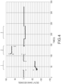
- the presence of an external magnetic field is indicated when a spike in voltage is detected in the signal provided by the driver.
- the presence of an external magnetic field is indicated when a step change in ⁇ T is detected.
- the third independent signal comprises a drive signal representing a drive mode other than the first bending mode.
- the presence of an external magnetic field is indicated when a zero-flow rate is compared to a measured asymmetry between an open loop driver signal i drive 2 , and pickoff voltages V LPO 2 , and V RPO 2 , wherein V LPO 2 , and V RPO 2 are pickoff voltages at a second bend mode frequency.
- a tamper correction factor is calculated and applied to the measured flowrate to offset the effect of an external magnetic field when the presence of an external magnetic field is detected.
- an alarm is triggered when the presence of an external magnetic field is detected.
- a method for operating a Coriolis flowmeter comprises flowing a flow material through flow conduits of the flowmeter and driving a driver connected to the flow conduits to oscillate the flow conduits in a first bending mode. Signals are received from pick-off sensors connected to the flow conduits. A presence of an external magnetic field is indicated if a magnetic field is detected.
- the presence of an external magnetic field is indicated when at least one of a spike and step change in voltage is detected in the signal provided by at least one of the pick-off sensors.
- the presence of an external magnetic field is indicated when a step change in ⁇ T is detected.
- a phase of each pick-off sensor is measured relative to a third independent signal comprising a drive signal representing a drive mode other than the first bending mode.
- the presence of an external magnetic field is indicated when a zero-flow rate is compared to a measured asymmetry between an open loop driver signal i drive 2 , and pickoff voltages V LPO 2 , and V RPO 2 , wherein V LPO 2 , and V RPO 2 are pickoff voltages at a second bend mode frequency.
- a tamper correction factor is calculated and applied to the measured flowrate to offset the effect of an external magnetic field when the presence of an external magnetic field is detected.
- an alarm is triggered when the presence of an external magnetic field is detected.
- FIGS. 1 - 9 and the following description depict specific examples to teach those skilled in the art how to make and use the best mode of embodiments of a sensor assembly, brace bars, drivers, and pickoff sensors.
- some conventional aspects have been simplified or omitted.
- Those skilled in the art will appreciate variations from these examples that fall within the scope of the present description.
- Those skilled in the art will appreciate that the features described below can be combined in various ways to form multiple variations of embodiments. As a result, the embodiments described below are not limited to the specific examples described below, but only by the claims and their equivalents.
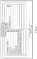
- FIG. 1 shows a flowmeter 5 according to an embodiment.
- the flowmeter 5 comprises a sensor assembly 10 and meter electronics 20.
- the meter electronics 20 is connected to the sensor assembly 10 via leads 100 and is configured to provide measurements of one or more of a density, mass flow rate, volume flow rate, totalized mass flow, temperature, or other measurements or information over a communication path 26.
- the flowmeter 5 can comprise a Coriolis mass flowmeter or other vibratory flowmeter. It should be apparent to those skilled in the art that the flowmeter 5 can comprise any manner of flowmeter 5, regardless of the number of drivers, pick-off sensors, flow conduits, or the operating mode of vibration.
- the sensor assembly 10 includes a pair of flanges 101 and 101', manifolds 102 and 102', a driver 104, pick-off sensors 105 and 105', and flow conduits 103A and 103B.
- the driver 104 and the pick-off sensors 105 and 105' are connected to the flow conduits 103A and 103B.
- the flanges 101 and 101' are affixed to the manifolds 102 and 102'.
- the manifolds 102 and 102' can be affixed to opposite ends of a spacer 106 in some embodiments.
- the spacer 106 maintains the spacing between the manifolds 102 and 102'.
- the process fluid enters the sensor assembly 10 through the flange 101, passes through the inlet manifold 102 where the total amount of process fluid is directed to enter the flow conduits 103A and 103B, flows through the flow conduits 103A and 103B and back into the outlet manifold 102', where it exits the sensor assembly 10 through the flange 101'.
- the process fluid can comprise a liquid.
- the process fluid can comprise a gas.
- the process fluid can comprise a multi-phase fluid, such as a liquid including entrained gases and/or entrained solids, for example without limitation.
- the flow conduits 103A and 103B are selected and appropriately mounted to the inlet manifold 102 and to the outlet manifold 102' so as to have substantially the same mass distribution, moments of inertia, and elastic moduli about the bending axes W-W and W'-W', respectively.
- the flow conduits 103A and 103B extend outwardly from the manifolds 102 and 102' in an essentially parallel fashion.
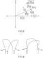
- the flow conduits 103A and 103B are driven by the driver 104 in opposite directions about the respective bending axes W and W' and at what is termed the first out of phase bending mode of the flowmeter 5.
- the driver 104 may comprise one of many well-known arrangements, such as a magnet mounted to the flow conduit 103A and an opposing coil mounted to the flow conduit 103B. An alternating current is passed through the opposing coil to cause both conduits to oscillate. A suitable drive signal is applied by the meter electronics 20 to the driver 104 via lead 110.
- Other driver devices are contemplated and are within the scope of the description and claims.
- the meter electronics 20 receives sensor signals on leads 111 and 111', respectively.
- the meter electronics 20 produces a drive signal on lead 110 which causes the driver 104 to oscillate the flow conduits 103A and 103B.
- Other sensor devices are contemplated and are within the scope of the description and claims.
- the meter electronics 20 processes the left and right velocity signals from the pick-off sensors 105 and 105' in order to compute a flow rate, among other things.
- the communication path 26 provides an input and an output means that allows the meter electronics 20 to interface with an operator or with other electronic systems.
- FIG. 1 is provided merely as an example of the operation of a flowmeter and is not intended to limit the teaching of the present invention. In embodiments, single tube and multi-tube flowmeters having one or more drivers and pickoffs are contemplated.
- the meter electronics 20 in one embodiment is configured to vibrate the flow conduit 103A and 103B.
- the vibration is performed by the driver 104.
- the meter electronics 20 further receives resulting vibrational signals from the pickoff sensors 105 and 105'.
- the vibrational signals comprise a vibrational response of the flow conduits 103A and 103B.
- the meter electronics 20 processes the vibrational response and determines a response frequency and/or phase difference.
- the meter electronics 20 processes the vibrational response and determines one or more flow measurements, including a mass flow rate and/or density of the process fluid. Other vibrational response characteristics and/or flow measurements are contemplated and are within the scope of the description and claims.
- the flow conduits 103A and 103B comprise substantially omega-shaped flow conduits, as shown.
- the flowmeter can comprise substantially straight flow conduits, U-shaped conduits, delta-shaped conduits, etc. Additional flowmeter shapes and/or configurations can be used and are within the scope of the description and claims.
- the time interval may be chosen to correspond to a block of time during which certain fluid conditions are detected, for example a liquid-only fluid state, or alternatively, a fluid state including liquids and entrained gas.
- certain fluid conditions for example a liquid-only fluid state, or alternatively, a fluid state including liquids and entrained gas.
- other mass flow and related quantifications are contemplated and are within the scope of the description and claims.
- V LPO represents the LPO voltage at the first bend mode frequency
- V LPO 2 represents the LPO voltage at the second bend mode frequency
Landscapes
- Physics & Mathematics (AREA)
- Fluid Mechanics (AREA)
- General Physics & Mathematics (AREA)
- Engineering & Computer Science (AREA)
- Signal Processing (AREA)
- Measuring Volume Flow (AREA)
Priority Applications (1)
| Application Number | Priority Date | Filing Date | Title |
|---|---|---|---|
| EP24214311.3A EP4488634A3 (de) | 2021-11-12 | 2021-11-12 | Vorrichtung und verfahren zur quantifizierung eines externen magnetfeldes für einen durchflussmesser |
Applications Claiming Priority (3)
| Application Number | Priority Date | Filing Date | Title |
|---|---|---|---|
| PCT/US2021/059129 WO2023086099A1 (en) | 2021-11-12 | 2021-11-12 | Coriolis flowmeter external magnetic field quantification apparatus and method |
| EP24214311.3A EP4488634A3 (de) | 2021-11-12 | 2021-11-12 | Vorrichtung und verfahren zur quantifizierung eines externen magnetfeldes für einen durchflussmesser |
| EP21824144.6A EP4430366A1 (de) | 2021-11-12 | 2021-11-12 | Vorrichtung und verfahren zur quantifizierung eines externen magnetfeldes für einen coriolisdurchflussmesser |
Related Parent Applications (1)
| Application Number | Title | Priority Date | Filing Date |
|---|---|---|---|
| EP21824144.6A Division EP4430366A1 (de) | 2021-11-12 | 2021-11-12 | Vorrichtung und verfahren zur quantifizierung eines externen magnetfeldes für einen coriolisdurchflussmesser |
Publications (2)
| Publication Number | Publication Date |
|---|---|
| EP4488634A2 true EP4488634A2 (de) | 2025-01-08 |
| EP4488634A3 EP4488634A3 (de) | 2025-03-26 |
Family
ID=78844730
Family Applications (4)
| Application Number | Title | Priority Date | Filing Date |
|---|---|---|---|
| EP21824144.6A Pending EP4430366A1 (de) | 2021-11-12 | 2021-11-12 | Vorrichtung und verfahren zur quantifizierung eines externen magnetfeldes für einen coriolisdurchflussmesser |
| EP24214277.6A Pending EP4488632A3 (de) | 2021-11-12 | 2021-11-12 | Vorrichtung und verfahren zur analyse eines externen magnetfeldes für einen durchflussmesser |
| EP24214282.6A Pending EP4488633A3 (de) | 2021-11-12 | 2021-11-12 | Vorrichtung und verfahren zur quantifizierung eines externen magnetfeldes für einen durchflussmesser |
| EP24214311.3A Pending EP4488634A3 (de) | 2021-11-12 | 2021-11-12 | Vorrichtung und verfahren zur quantifizierung eines externen magnetfeldes für einen durchflussmesser |
Family Applications Before (3)
| Application Number | Title | Priority Date | Filing Date |
|---|---|---|---|
| EP21824144.6A Pending EP4430366A1 (de) | 2021-11-12 | 2021-11-12 | Vorrichtung und verfahren zur quantifizierung eines externen magnetfeldes für einen coriolisdurchflussmesser |
| EP24214277.6A Pending EP4488632A3 (de) | 2021-11-12 | 2021-11-12 | Vorrichtung und verfahren zur analyse eines externen magnetfeldes für einen durchflussmesser |
| EP24214282.6A Pending EP4488633A3 (de) | 2021-11-12 | 2021-11-12 | Vorrichtung und verfahren zur quantifizierung eines externen magnetfeldes für einen durchflussmesser |
Country Status (9)
| Country | Link |
|---|---|
| US (2) | US20240426645A1 (de) |
| EP (4) | EP4430366A1 (de) |
| JP (1) | JP7850806B2 (de) |
| KR (1) | KR20240107173A (de) |
| CN (1) | CN118235019A (de) |
| AU (1) | AU2021473846B2 (de) |
| CA (1) | CA3238148A1 (de) |
| MX (1) | MX2024004238A (de) |
| WO (1) | WO2023086099A1 (de) |
Families Citing this family (1)
| Publication number | Priority date | Publication date | Assignee | Title |
|---|---|---|---|---|
| WO2025085049A1 (en) * | 2023-10-16 | 2025-04-24 | Micro Motion, Inc. | Coriolis flowmeter with external magnetic field detection and related method |
Citations (3)
| Publication number | Priority date | Publication date | Assignee | Title |
|---|---|---|---|---|
| US4109524A (en) | 1975-06-30 | 1978-08-29 | S & F Associates | Method and apparatus for mass flow rate measurement |
| USRE31450E (en) | 1977-07-25 | 1983-11-29 | Micro Motion, Inc. | Method and structure for flow measurement |
| US4491025A (en) | 1982-11-03 | 1985-01-01 | Micro Motion, Inc. | Parallel path Coriolis mass flow rate meter |
Family Cites Families (7)
| Publication number | Priority date | Publication date | Assignee | Title |
|---|---|---|---|---|
| JPH05180680A (ja) * | 1991-12-27 | 1993-07-23 | Tokico Ltd | 振動式測定装置 |
| JPH109925A (ja) * | 1996-06-20 | 1998-01-16 | Oval Corp | コリオリ流量計 |
| JP2007263859A (ja) * | 2006-03-29 | 2007-10-11 | Hitachi Ltd | 振動式計測装置 |
| JP6406043B2 (ja) * | 2015-02-05 | 2018-10-17 | 横河電機株式会社 | 測定装置の共振回路 |
| DE102018133117A1 (de) | 2018-12-20 | 2020-06-25 | Endress+Hauser Flowtec Ag | Coriolis-Massendurchfluß-Meßgerät |
| EP3899448B1 (de) * | 2018-12-21 | 2024-03-27 | Endress + Hauser Flowtec AG | Coriolis-massendurchfluss-messer mit magnetfelddetektor |
| DE102019133610A1 (de) * | 2019-12-09 | 2021-06-10 | Endress + Hauser Flowtec Ag | Vibronisches Meßsystem zum Messen eines Massestroms eines fluiden Meßstoff |
-
2021
- 2021-11-12 EP EP21824144.6A patent/EP4430366A1/de active Pending
- 2021-11-12 EP EP24214277.6A patent/EP4488632A3/de active Pending
- 2021-11-12 KR KR1020247019333A patent/KR20240107173A/ko active Pending
- 2021-11-12 US US18/700,908 patent/US20240426645A1/en active Pending
- 2021-11-12 MX MX2024004238A patent/MX2024004238A/es unknown
- 2021-11-12 EP EP24214282.6A patent/EP4488633A3/de active Pending
- 2021-11-12 JP JP2024527640A patent/JP7850806B2/ja active Active
- 2021-11-12 WO PCT/US2021/059129 patent/WO2023086099A1/en not_active Ceased
- 2021-11-12 CN CN202180104165.1A patent/CN118235019A/zh active Pending
- 2021-11-12 AU AU2021473846A patent/AU2021473846B2/en active Active
- 2021-11-12 EP EP24214311.3A patent/EP4488634A3/de active Pending
- 2021-11-12 CA CA3238148A patent/CA3238148A1/en active Pending
-
2025
- 2025-10-24 US US19/368,754 patent/US20260049855A1/en active Pending
Patent Citations (4)
| Publication number | Priority date | Publication date | Assignee | Title |
|---|---|---|---|---|
| US4109524A (en) | 1975-06-30 | 1978-08-29 | S & F Associates | Method and apparatus for mass flow rate measurement |
| USRE31450E (en) | 1977-07-25 | 1983-11-29 | Micro Motion, Inc. | Method and structure for flow measurement |
| US4491025A (en) | 1982-11-03 | 1985-01-01 | Micro Motion, Inc. | Parallel path Coriolis mass flow rate meter |
| US4491025B1 (de) | 1982-11-03 | 1988-01-05 |
Also Published As
| Publication number | Publication date |
|---|---|
| US20240426645A1 (en) | 2024-12-26 |
| AU2021473846B2 (en) | 2025-04-17 |
| EP4488634A3 (de) | 2025-03-26 |
| EP4488632A2 (de) | 2025-01-08 |
| EP4430366A1 (de) | 2024-09-18 |
| AU2021473846A1 (en) | 2024-04-18 |
| JP2024541346A (ja) | 2024-11-08 |
| JP7850806B2 (ja) | 2026-04-23 |
| WO2023086099A1 (en) | 2023-05-19 |
| CN118235019A (zh) | 2024-06-21 |
| EP4488632A3 (de) | 2025-03-26 |
| KR20240107173A (ko) | 2024-07-08 |
| EP4488633A2 (de) | 2025-01-08 |
| US20260049855A1 (en) | 2026-02-19 |
| CA3238148A1 (en) | 2023-05-19 |
| MX2024004238A (es) | 2024-04-24 |
| EP4488633A3 (de) | 2025-03-26 |
Similar Documents
| Publication | Publication Date | Title |
|---|---|---|
| US8589091B2 (en) | System, method, and computer program product for detecting a process disturbance in a vibrating flow device | |
| EP2724125B1 (de) | Vibrationsdurchflussmesser und nullkontrollverfahren | |
| JP5497117B2 (ja) | コリオリ流量計内を流れる物質の不均一性を高速検出するための方法及び計測器電子機器 | |
| EP1019681B1 (de) | Kombinierte detektor und schwingungserreger um in coriolisströmungsmessern zu verwenden und verfahren zu deren betrieb | |
| US20260056045A1 (en) | Flowmeter false totalizing elimination devices and methods | |
| US20260049855A1 (en) | Coriolis flowmeter external magnetic field quantification apparatus and method | |
| US20260036456A1 (en) | Coriolis flowmeter with detection of an external magnet field | |
| US20250321130A1 (en) | Coriolis flowmeter with compensation for an external magnetic field | |
| RU2836164C2 (ru) | Оборудование и способ для количественного определения внешнего магнитного поля кориолисова расходомера | |
| WO2025085049A1 (en) | Coriolis flowmeter with external magnetic field detection and related method | |
| WO2024072431A1 (en) | Flowmeter magnetic shielding apparatus and method |
Legal Events
| Date | Code | Title | Description |
|---|---|---|---|
| PUAI | Public reference made under article 153(3) epc to a published international application that has entered the european phase |
Free format text: ORIGINAL CODE: 0009012 |
|
| STAA | Information on the status of an ep patent application or granted ep patent |
Free format text: STATUS: THE APPLICATION HAS BEEN PUBLISHED |
|
| AC | Divisional application: reference to earlier application |
Ref document number: 4430366 Country of ref document: EP Kind code of ref document: P |
|
| AK | Designated contracting states |
Kind code of ref document: A2 Designated state(s): AL AT BE BG CH CY CZ DE DK EE ES FI FR GB GR HR HU IE IS IT LI LT LU LV MC MK MT NL NO PL PT RO RS SE SI SK SM TR |
|
| REG | Reference to a national code |
Ref country code: DE Ref legal event code: R079 Free format text: PREVIOUS MAIN CLASS: G01F0015000000 Ipc: G01F0001840000 |
|
| P01 | Opt-out of the competence of the unified patent court (upc) registered |
Free format text: CASE NUMBER: APP_1207/2025 Effective date: 20250108 |
|
| PUAL | Search report despatched |
Free format text: ORIGINAL CODE: 0009013 |
|
| AK | Designated contracting states |
Kind code of ref document: A3 Designated state(s): AL AT BE BG CH CY CZ DE DK EE ES FI FR GB GR HR HU IE IS IT LI LT LU LV MC MK MT NL NO PL PT RO RS SE SI SK SM TR |
|
| RIC1 | Information provided on ipc code assigned before grant |
Ipc: G01F 15/00 20060101ALI20250217BHEP Ipc: G01F 1/84 20060101AFI20250217BHEP |
|
| STAA | Information on the status of an ep patent application or granted ep patent |
Free format text: STATUS: REQUEST FOR EXAMINATION WAS MADE |
|
| 17P | Request for examination filed |
Effective date: 20250625 |
|
| STAA | Information on the status of an ep patent application or granted ep patent |
Free format text: STATUS: EXAMINATION IS IN PROGRESS |
|
| 17Q | First examination report despatched |
Effective date: 20260324 |