EP4489117A1 - Matériau actif d'électrode négative pour batterie secondaire à électrolyte non aqueux et batterie secondaire à électrolyte non aqueux - Google Patents
Matériau actif d'électrode négative pour batterie secondaire à électrolyte non aqueux et batterie secondaire à électrolyte non aqueux Download PDFInfo
- Publication number
- EP4489117A1 EP4489117A1 EP23759693.7A EP23759693A EP4489117A1 EP 4489117 A1 EP4489117 A1 EP 4489117A1 EP 23759693 A EP23759693 A EP 23759693A EP 4489117 A1 EP4489117 A1 EP 4489117A1
- Authority
- EP
- European Patent Office
- Prior art keywords
- equal
- negative electrode
- phase
- secondary battery
- electrolyte secondary
- Prior art date
- Legal status (The legal status is an assumption and is not a legal conclusion. Google has not performed a legal analysis and makes no representation as to the accuracy of the status listed.)
- Pending
Links
Images


Classifications
-
- H—ELECTRICITY
- H01—ELECTRIC ELEMENTS
- H01M—PROCESSES OR MEANS, e.g. BATTERIES, FOR THE DIRECT CONVERSION OF CHEMICAL ENERGY INTO ELECTRICAL ENERGY
- H01M4/00—Electrodes
- H01M4/02—Electrodes composed of, or comprising, active material
- H01M4/36—Selection of substances as active materials, active masses, active liquids
- H01M4/362—Composites
- H01M4/366—Composites as layered products
-
- H—ELECTRICITY
- H01—ELECTRIC ELEMENTS
- H01M—PROCESSES OR MEANS, e.g. BATTERIES, FOR THE DIRECT CONVERSION OF CHEMICAL ENERGY INTO ELECTRICAL ENERGY
- H01M10/00—Secondary cells; Manufacture thereof
- H01M10/05—Accumulators with non-aqueous electrolyte
- H01M10/052—Li-accumulators
-
- H—ELECTRICITY
- H01—ELECTRIC ELEMENTS
- H01M—PROCESSES OR MEANS, e.g. BATTERIES, FOR THE DIRECT CONVERSION OF CHEMICAL ENERGY INTO ELECTRICAL ENERGY
- H01M4/00—Electrodes
- H01M4/02—Electrodes composed of, or comprising, active material
- H01M4/36—Selection of substances as active materials, active masses, active liquids
- H01M4/362—Composites
- H01M4/364—Composites as mixtures
-
- H—ELECTRICITY
- H01—ELECTRIC ELEMENTS
- H01M—PROCESSES OR MEANS, e.g. BATTERIES, FOR THE DIRECT CONVERSION OF CHEMICAL ENERGY INTO ELECTRICAL ENERGY
- H01M4/00—Electrodes
- H01M4/02—Electrodes composed of, or comprising, active material
- H01M4/36—Selection of substances as active materials, active masses, active liquids
- H01M4/38—Selection of substances as active materials, active masses, active liquids of elements or alloys
- H01M4/386—Silicon or alloys based on silicon
-
- H—ELECTRICITY
- H01—ELECTRIC ELEMENTS
- H01M—PROCESSES OR MEANS, e.g. BATTERIES, FOR THE DIRECT CONVERSION OF CHEMICAL ENERGY INTO ELECTRICAL ENERGY
- H01M4/00—Electrodes
- H01M4/02—Electrodes composed of, or comprising, active material
- H01M4/36—Selection of substances as active materials, active masses, active liquids
- H01M4/48—Selection of substances as active materials, active masses, active liquids of inorganic oxides or hydroxides
- H01M4/485—Selection of substances as active materials, active masses, active liquids of inorganic oxides or hydroxides of mixed oxides or hydroxides for inserting or intercalating light metals, e.g. LiTi2O4 or LiTi2OxFy
-
- H—ELECTRICITY
- H01—ELECTRIC ELEMENTS
- H01M—PROCESSES OR MEANS, e.g. BATTERIES, FOR THE DIRECT CONVERSION OF CHEMICAL ENERGY INTO ELECTRICAL ENERGY
- H01M4/00—Electrodes
- H01M4/02—Electrodes composed of, or comprising, active material
- H01M4/36—Selection of substances as active materials, active masses, active liquids
- H01M4/58—Selection of substances as active materials, active masses, active liquids of inorganic compounds other than oxides or hydroxides, e.g. sulfides, selenides, tellurides, halogenides or LiCoFy; of polyanionic structures, e.g. phosphates, silicates or borates
- H01M4/5825—Oxygenated metallic salts or polyanionic structures, e.g. borates, phosphates, silicates, olivines
-
- H—ELECTRICITY
- H01—ELECTRIC ELEMENTS
- H01M—PROCESSES OR MEANS, e.g. BATTERIES, FOR THE DIRECT CONVERSION OF CHEMICAL ENERGY INTO ELECTRICAL ENERGY
- H01M4/00—Electrodes
- H01M4/02—Electrodes composed of, or comprising, active material
- H01M4/36—Selection of substances as active materials, active masses, active liquids
- H01M4/58—Selection of substances as active materials, active masses, active liquids of inorganic compounds other than oxides or hydroxides, e.g. sulfides, selenides, tellurides, halogenides or LiCoFy; of polyanionic structures, e.g. phosphates, silicates or borates
- H01M4/583—Carbonaceous material, e.g. graphite-intercalation compounds or CFx
-
- H—ELECTRICITY
- H01—ELECTRIC ELEMENTS
- H01M—PROCESSES OR MEANS, e.g. BATTERIES, FOR THE DIRECT CONVERSION OF CHEMICAL ENERGY INTO ELECTRICAL ENERGY
- H01M4/00—Electrodes
- H01M4/02—Electrodes composed of, or comprising, active material
- H01M2004/021—Physical characteristics, e.g. porosity, surface area
-
- H—ELECTRICITY
- H01—ELECTRIC ELEMENTS
- H01M—PROCESSES OR MEANS, e.g. BATTERIES, FOR THE DIRECT CONVERSION OF CHEMICAL ENERGY INTO ELECTRICAL ENERGY
- H01M4/00—Electrodes
- H01M4/02—Electrodes composed of, or comprising, active material
- H01M2004/022—Electrodes made of one single microscopic fiber
-
- H—ELECTRICITY
- H01—ELECTRIC ELEMENTS
- H01M—PROCESSES OR MEANS, e.g. BATTERIES, FOR THE DIRECT CONVERSION OF CHEMICAL ENERGY INTO ELECTRICAL ENERGY
- H01M4/00—Electrodes
- H01M4/02—Electrodes composed of, or comprising, active material
- H01M2004/026—Electrodes composed of, or comprising, active material characterised by the polarity
- H01M2004/027—Negative electrodes
-
- Y—GENERAL TAGGING OF NEW TECHNOLOGICAL DEVELOPMENTS; GENERAL TAGGING OF CROSS-SECTIONAL TECHNOLOGIES SPANNING OVER SEVERAL SECTIONS OF THE IPC; TECHNICAL SUBJECTS COVERED BY FORMER USPC CROSS-REFERENCE ART COLLECTIONS [XRACs] AND DIGESTS
- Y02—TECHNOLOGIES OR APPLICATIONS FOR MITIGATION OR ADAPTATION AGAINST CLIMATE CHANGE
- Y02E—REDUCTION OF GREENHOUSE GAS [GHG] EMISSIONS, RELATED TO ENERGY GENERATION, TRANSMISSION OR DISTRIBUTION
- Y02E60/00—Enabling technologies; Technologies with a potential or indirect contribution to GHG emissions mitigation
- Y02E60/10—Energy storage using batteries
Definitions
- the present disclosure relates to a negative electrode active material for a non-aqueous electrolyte secondary battery and a non-aqueous electrolyte secondary battery using this negative electrode active material.
- non-aqueous electrolyte secondary batteries such as lithium-ion batteries have been widely used for use requiring a high capacity, such as on-board use and power storage use.
- a negative electrode active material which is a main constituent of a negative electrode, is one of important factors for attempting to increase the capacity of the battery, and therefore various investigations have been made on the negative electrode active material.
- use of a material containing silicon (Si-containing material) has attracted attention as a negative electrode active material having a high theoretical capacity density.
- SiOx a material in which silicon particles are dispersed in a SiO 2 phase
- LSX a material in which silicon particles are dispersed in a lithium silicate phase represented by Li 2z SiO 2+z (0 ⁇ z ⁇ 2)
- PATENT LITERATURE 1 International Publication No. 2016/35290
- LSX has a small irreversible capacity compared with SiOx, and has excellent initial charge-discharge efficiency.
- the lithium silicate phase in LSX has low alkali resistance (stability against Li), and may still cause side reactions with Li ions during initial charge, and further improvement of the initial charge-discharge efficiency has been required.
- Si-containing material such as LSX causes a large change in volume with charge and discharge, cracking, breakage, and the like easily occur with repeated charge and discharge. It is not easy to achieve good cycle characteristics.
- a negative electrode active material for a non-aqueous electrolyte secondary battery comprises composite particles including: a lithium aluminate phase; and a silicon phase dispersed in the lithium aluminate phase, wherein the composite particles have a porosity inside the particles of less than or equal to 25% before first charge and discharge.
- the non-aqueous electrolyte secondary battery having high capacity and excellent cycle characteristics may be achieved.
- a non-aqueous electrolyte secondary battery using the negative electrode active material according to the present disclosure has, for example, good cycle characteristics, and has high initial charge-discharge efficiency compared with a case of using LSX.
- the present inventors have ascertained that initial charge-discharge efficiency of a battery is remarkably improved, compared with a case of using LSX, by using composite particles in which a silicon phase is dispersed in a lithium aluminate phase as a negative electrode active material for a non-aqueous electrolyte secondary battery.
- the composite particles including the lithium aluminate phase have a higher theoretical capacity density than a carbon-based active material such as graphite, similarly to other Si-containing materials, and contribute to increase in the capacity of the battery.
- a cylindrical battery housing a wound electrode assembly 14 in a bottomed cylindrical exterior housing can 16 will be exemplified as the non-aqueous electrolyte secondary battery, but the exterior of the battery is not limited to the cylindrical exterior housing can.
- the non-aqueous electrolyte secondary battery according to the present disclosure may be, for example, a rectangular battery comprising a rectangular exterior housing can, a coin-shaped battery comprising a coin-shaped exterior housing can, or a laminated battery comprising an exterior composed of a laminate sheet including a metal layer and a resin layer.
- the electrode assembly is not limited to the wound electrode assembly, and may be a stacked electrode assembly in which a plurality of positive electrodes and a plurality of negative electrodes are alternately stacked via a separator.
- FIG. 1 is a sectional view of a non-aqueous electrolyte secondary battery 10 of an example of an embodiment.
- the non-aqueous electrolyte secondary battery 10 comprises the wound electrode assembly 14, an electrolyte, and the exterior housing can 16 housing the electrode assembly 14 and the non-aqueous electrolyte.
- the electrode assembly 14 has a positive electrode 11, a negative electrode 12, and a separator 13, and has a wound structure in which the positive electrode 11 and the negative electrode 12 are spirally wound via the separator 13.
- the exterior housing can 16 is a bottomed cylindrical metallic container having an opening on one end side in an axial direction, and the opening of the exterior housing can 16 is sealed with a sealing assembly 17.
- the sealing assembly 17 side of the battery will be described as the upper side
- the bottom side of the exterior housing can 16 will be described as the lower side.
- the non-aqueous electrolyte includes a non-aqueous solvent and an electrolyte salt dissolved in the non-aqueous solvent.
- the non-aqueous solvent esters, ethers, nitriles, amides, a mixed solvent of two or more thereof, and the like are used, for example.
- the non-aqueous solvent may contain a halogen-substituted derivative in which hydrogen of these solvents is at least partially substituted with a halogen atom such as fluorine.
- An example of the non-aqueous solvent is ethylene carbonate (EC), ethyl methyl carbonate (EMC), dimethyl carbonate (DMC), diethyl carbonate (DEC), a mixed solvent thereof, or the like.
- a lithium salt such as LiPF 6 is used, for example.
- the positive electrode 11, the negative electrode 12, and the separator 13, which constitute the electrode assembly 14, are all a band-shaped elongated body, and spirally wound to be alternately stacked in a radial direction of the electrode assembly 14.
- the negative electrode 12 is formed to be one size larger than the positive electrode 11. That is, the negative electrode 12 is formed to be longer than the positive electrode 11 in a longitudinal direction and a width direction (short direction).
- Two of the separator 13 are formed to be one size larger than at least the positive electrode 11, and disposed to sandwich the positive electrode 11, for example.
- the electrode assembly 14 has a positive electrode lead 20 connected to the positive electrode 11 by welding or the like and a negative electrode lead 21 connected to the negative electrode 12 by welding or the like.
- the positive electrode 11 has a positive electrode core and a positive electrode mixture layer formed on the positive electrode core.
- a foil of a metal stable within a potential range of the positive electrode 11, such as aluminum and an aluminum alloy, a film in which such a metal is disposed on a surface layer, or the like may be used.
- the positive electrode mixture layer includes a positive electrode active material, a conductive agent, and a binder, and is preferably formed on both surfaces of the positive electrode core except for an exposed portion where the positive electrode lead 20 is to be welded.
- the positive electrode 11 may be produced by, for example, applying a positive electrode slurry including the positive electrode active material, the conductive agent, the binder, and the like on the positive electrode core, and drying and then compressing the applied film to form the positive electrode mixture layer on both surfaces of the positive electrode core.
- the positive electrode mixture layer includes a particulate lithium-metal composite oxide as the positive electrode active material.
- the lithium-metal composite oxide is a composite oxide containing a metal element such as Co, Mn, Ni, and Al in addition to Li.
- the metal element to constitute the lithium-metal composite oxide is, for example, at least one selected from the group consisting of Mg, Al, Ca, Sc, Ti, V, Cr, Mn, Fe, Co, Ni, Cu, Zn, Ga, Ge, Y, Zr, Sn, Sb, W, Pb, and Bi. Among these, at least one selected from the group consisting of Co, Ni, and Mn is preferably contained.
- a preferable example of the composite oxide is a lithium-metal composite oxide containing Ni, Co, and Mn, or a lithium-metal composite oxide containing Ni, Co, and Al.
- Examples of the conductive agent included in the positive electrode mixture layer may include carbon materials such as carbon black such as acetylene black and Ketjenblack, graphite, carbon nanotube (CNT), carbon nanofiber, and graphene.
- Examples of the binder included in the positive electrode mixture layer may include fluorine-containing resins such as polytetrafluoroethylene (PTFE) and polyvinylidene fluoride (PVDF), polyacrylonitrile (PAN), a polyimide, an acrylic resin, and a polyolefin. These resins may be used in combination with carboxymethylcellulose (CMC) or a salt thereof, polyethylene oxide (PEO), and the like.
- the negative electrode 12 has a negative electrode core and a negative electrode mixture layer formed on the negative electrode core.
- a foil of a metal stable within a potential range of the negative electrode 12, such as copper and a copper alloy, a film in which such a metal is disposed on a surface layer, or the like may be used.
- the negative electrode mixture layer includes a negative electrode active material, a binder, and a conductive agent as necessary, and is preferably formed on both surfaces of the negative electrode core except for an exposed portion where the negative electrode lead 21 is to be welded.
- the negative electrode 12 may be produced by applying a negative electrode slurry including the negative electrode active material, the binder, and the like on surfaces of the negative electrode core, and drying and then compressing the applied film to form the negative electrode mixture layer on both surfaces of the negative electrode core.
- a fluororesin, PAN, a polyimide, an acrylic resin, a polyolefin, and the like may be used as in the case of the positive electrode 11, but styrene-butadiene rubber (SBR) is preferably used.
- the negative electrode mixture layer preferably includes CMC or a salt thereof, polyacrylic acid (PAA) or a salt thereof, polyvinyl alcohol (PVA), and the like. Among these, SBR; and CMC or a salt thereof, or PAA or a salt thereof are preferably used in combination.
- the negative electrode mixture layer may include a conductive agent such as CNT.
- a porous sheet having an ion permeation property and an insulation property is used.
- the porous sheet include a fine porous thin film, a woven fabric, and a nonwoven fabric.
- a polyolefin such as polyethylene and polypropylene, cellulose, and the like are preferable.
- the separator 13 may have a single layer structure or a multilayer structure.
- a highly heat-resistant resin layer such as an aramid resin may be formed on a surface of the separator 13.
- a filler layer including an inorganic filler may be formed on an interface between the separator 13 and at least one of the positive electrode 11 and the negative electrode 12.
- the inorganic filler include oxides containing metal elements such as Ti, Al, Si, and Mg, and a phosphoric acid compound.
- the filler layer may be formed by applying a slurry containing the filler on the surface of the positive electrode 11, the negative electrode 12, or the separator 13.
- Insulating plates 18 and 19 are disposed on the upper and lower sides of the electrode assembly 14, respectively.
- the positive electrode lead 20 extends through a through hole of the insulating plate 18 toward the sealing assembly 17 side
- the negative electrode lead 21 extends through an outside of the insulating plate 19 toward the bottom side of the exterior housing can 16.
- the positive electrode lead 20 is connected to a lower surface of an internal terminal plate 23 of the sealing assembly 17 by welding or the like, and a cap 27, which is a top plate of the sealing assembly 17 electrically connected to the internal terminal plate 23, becomes a positive electrode terminal.
- the negative electrode lead 21 is connected to a bottom inner surface of the exterior housing can 16 by welding or the like, and the exterior housing can 16 becomes a negative electrode terminal.
- a gasket 28 is provided between the exterior housing can 16 and the sealing assembly 17 to achieve sealability inside the battery.
- a grooved portion 22 in which a part of a side wall thereof projects inward to support the sealing assembly 17 is formed.
- the grooved portion 22 is preferably formed in a circular shape along a circumferential direction of the exterior housing can 16, and supports the sealing assembly 17 with the upper face thereof.
- the sealing assembly 17 is fixed on the upper part of the exterior housing can 16 with the grooved portion 22 and with an end of the opening of the exterior housing can 16 caulked to the sealing assembly 17.
- the sealing assembly 17 has a stacked structure of the internal terminal plate 23, a lower vent member 24, an insulating member 25, an upper vent member 26, and the cap 27 in this order from the electrode assembly 14 side.
- Each member constituting the sealing assembly 17 has, for example, a disk shape or a ring shape, and each member except for the insulating member 25 is electrically connected to each other.
- the lower vent member 24 and the upper vent member 26 are connected at each of central parts thereof, and the insulating member 25 is interposed between each of the circumferential parts. If the internal pressure of the battery increases due to abnormal heat generation, the lower vent member 24 is deformed so as to push the upper vent member 26 up toward the cap 27 side and breaks, and thereby a current pathway between the lower vent member 24 and the upper vent member 26 is cut off. If the internal pressure further increases, the upper vent member 26 breaks, and gas is discharged through an opening of the cap 27.
- FIG. 2 is a schematic view illustrating a cross section of a composite particle 30 of an example of an embodiment.
- the negative electrode 12 includes at least the composite particle 30 as the negative electrode active material, and preferably includes the composite particle 30 and a carbon material. Use in combination of the composite particle 30 and the carbon material as the negative electrode active material easily achieves both of the high capacity and the excellent cycle characteristics.
- a content of the carbon material is preferably less than or equal to 98 mass%, more preferably greater than or equal to 70 mass% and less than or equal to 98 mass%, and particularly preferably greater than or equal to 75 mass% and less than or equal to 95 mass% relative to a total mass of the negative electrode active material.
- Examples of the carbon material may include graphite, easily graphitized carbon (soft carbon), and hardly graphitized carbon (hard carbon).
- graphite which has excellent stability of charge and discharge and has a small irreversible capacity, is preferable.
- the graphite may be any of artificial graphite such as massive artificial graphite (MAG) and graphitized mesophase-carbon microbead (MCMB); and natural graphite such as flake graphite, massive graphite, and amorphous graphite.
- MAG massive artificial graphite
- MCMB graphitized mesophase-carbon microbead
- the composite particle 30 includes a lithium aluminate phase 31 and a silicon phase 32 dispersed in the lithium aluminate phase 31.
- the composite particle 30 preferably includes a conductive layer 34 formed on surfaces of base particles 33 composed of the lithium aluminate phase 31 and the silicon phase 32.
- the base particles 33 have a sea-island structure in which the fine silicon phase 32 is dispersed in a matrix of the lithium aluminate phase 31.
- Gaps 35 are present inside the base particles 33, but a porosity of the composite particle 30 before first charge and discharge is less than or equal to 25%. Although the gaps 35 are considered to be a trigger of cracking, breakage, and the like with repeated charge and discharge, reducing the porosity to be less than or equal to 25% may effectively inhibit deterioration of the particle structure.
- the lithium aluminate phase 31 has more excellent alkali resistance than a lithium silicate phase in LSX particles.
- use of the composite particle 30 as the negative electrode active material inhibits side reactions with Li ions during initial charge compared with a case of using LSX to inhibit deterioration of the negative electrode active material due to the side reactions and decrease in an initial capacity due to the deterioration. That is, decrease in initial charge-discharge efficiency is highly inhibited.
- the composite particle 30 may substantially not include lithium silicate and SiO 2 . Although the composite particle 30 may include lithium silicate and SiO 2 , their contents are desirably small. The total content of lithium silicate and SiO 2 in the composite particle 30 is, for example, less than or equal to 3 mass%.
- a content rate of aluminum (Al) (MAl) relative to a total mass of elements other than oxygen is preferably greater than or equal to 10 mass% and less than or equal to 47 mass%.
- a content rate of lithium (Li) (MLi) relative to the total mass of elements other than oxygen is preferably greater than or equal to 0.7 mass% and less than or equal to 13.5 mass%.
- a ratio (MLi/MAl) of the content rate of lithium (MLi) to the content rate of aluminum (MAl) is preferably greater than or equal to 0.04 and less than or equal to 0.50, and more preferably greater than or equal to 0.05 and less than or equal to 0.25 from the viewpoints of stability, ion conductivity, reduction in the porosity of the lithium aluminate phase 31, and the like.
- the content rate (MAl) is more preferably greater than or equal to 11.5 mass% and less than or equal to 45.5 mass%.
- the content rate (MLi) is more preferably greater than or equal to 1.0 mass% and less than or equal to 9.5 mass%, and particularly preferably greater than or equal to 1.5 mass% and less than or equal to 3.5 mass%.
- a content rate of silicon (Si) (MSi) relative to the total mass of elements other than oxygen is preferably greater than or equal to 40 mass% and less than or equal to 90 mass%, and more preferably greater than or equal to 50.8 mass% and less than or equal to 85.5 mass%. In this case, both of the high capacity and the good cycle characteristics are easily achieved.
- the content rate of Si (MSi) refers to an amount of Si constituting the silicon phase 32 in the composite particle 30.
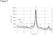
- x° is at least one selected from the group consisting of 19.4°, 22.3°, 31.9°, 34.3°, and 37.5°.
- K ⁇ ray of Cu is used.
- near x° herein means being within a range of, for example, x ⁇ 1°.
- a highly crystalline fine Al 2 O 3 phase may be dispersed.
- the Al 2 O 3 phase is distributed as islands in the matrix of the lithium aluminate phase 31, for example. In this case, expansion and breakage of the lithium aluminate phase 31 due to expansion and contraction of the silicon phase 32 are easily inhibited to increase the effect of improving the cycle characteristics.
- a content of the Al 2 O 3 phase in the composite particle 30 is, for example, less than or equal to 10 mass%.
- FIG. 3 indicates an example of the XRD patterns of the composite particle 30 (base particles 33).
- a solid line in FIG. 3 represents an XRD pattern of Al-rich composite particle 30 with a large MAl/MLi.
- a broken line in FIG. 3 represents an XRD pattern of Li-rich composite particle 30 with a small MAl/MLi.
- (i) to (v) represent peaks derived from lithium aluminate.
- the base particle 33 of the composite particle 30 has the sea-island structure in which the fine silicon phase 32, which includes island parts, are dispersed in the lithium aluminate phase 31, which is a sea part.
- the lithium aluminate phase 31 has good ion conductivity, and the silicon phase 32 smoothly occludes and releases Li ions through the lithium aluminate phase 31.
- the lithium aluminate phase 31 relaxes an effect of expansion and contraction of the silicon phase 32.
- the lithium aluminate phase 31 may be amorphous, and the lithium aluminate phase 31 in this case may more effectively relax the effect of expansion and contraction of the silicon phase 32.
- a plurality of primary particles including the lithium aluminate phase 31 and the silicon phase 32 is bonded to constitute secondary particles, for example.
- An average particle diameter of the composite particle 30 (secondary particles) is, for example, greater than or equal to 1 ⁇ m and less than or equal to 25 ⁇ m, and may be greater than or equal to 4 ⁇ m and less than or equal to 15 ⁇ m. In this case, stress due to change in volume of the composite particle 30 with charge and discharge is easily relaxed, and good cycle characteristics are easily obtained.
- a surface area of the composite particle 30 becomes an appropriate size to inhibit decrease in the capacity due to side reactions with the non-aqueous electrolyte.
- the average particle diameter of the composite particle 30 means a particle diameter at which a volumetric integrated value is 50% in a particle size distribution measured by a laser diffraction scattering method (volume-average particle diameter).
- volume-average particle diameter For the measurement apparatus, "LA-750", manufactured by HORIBA, Ltd., may be used, for example.
- a thickness of the conductive layer 34 is substantially small so as not to affect the average particle diameter of the composite particle 30, and thereby the average particle diameter of the composite particle 30 having the conductive layer 34 may be regarded as the average particle diameter of the composite particle 30.
- the composite particle 30 may be taken out of the battery by the following method. First, the battery in a fully discharged state is disassembled to take out the negative electrode, and the negative electrode is washed with anhydrous ethyl methyl carbonate or dimethyl carbonate to remove the non-aqueous electrolyte component. The negative electrode mixture layer is peeled from copper foil, which is the negative electrode core, and the mixture layer is crushed with a mortar to obtain a sample powder. Then, the sample powder is dried in a dry atmosphere for 1 hour, and immersed in weekly boiled 6-M hydrochloric acid for 10 minutes to remove elements derived from components other than the composite particle.
- the fully discharged state refers to a state where a depth of discharge (DOD) is greater than or equal to 90% (state of charge (SOC) is less than or equal to 10%).
- DOD depth of discharge
- SOC state of charge
- the lithium aluminate phase 31 is a phase of a composite oxide including Li, Al, and O.
- An atomic ratio of O to Al (O/Al) in the lithium aluminate is, for example, greater than or equal to 1.6 and less than or equal to 4.
- An atomic ratio of Li to Al (Li/Al) in the lithium aluminate is, for example, greater than or equal to 1/5 and less than or equal to 5.
- a composition of the lithium aluminate may be represented by the formula: Li u AlO (3+u)/2 .
- "u" in the formula is, for example, greater than 0 and less than or equal to 5, and may be greater than 0 and less than or equal to 1.
- the composition may be represented by LiAl 5 O 8
- the composition may be represented by Li 2 Al 4 O 7
- the composition may be represented by LiAlO 2
- the composition may be represented by Li 5 AlO 4 .
- the lithium aluminate phase 31 preferably includes at least one selected from the group consisting of LiAl 5 O 8 , Li 2 Al 4 O 7 , LiAlO 2 , and Li 5 AlO 4 .
- the lithium aluminate phase 31 more preferably includes LiAlO 2 as a main component.
- “main component” means a component accounting for greater than or equal to 50 mass% in a total mass of the lithium aluminate phase 31.
- a content rate of LiAlO 2 may be greater than or equal to 70 mass%.
- the lithium aluminate phase 31 may further contain another element M in addition to Li, Al, and O.
- the element M is, for example, at least one selected from the group consisting of sodium (Na), potassium (K), calcium (Ca), magnesium (Mg), zirconium (Zr), iron (Fe), boron (B), phosphorus (P), and lanthanum (La).
- the lithium aluminate phase 31 including the element M more improves stability and ion conductivity of the lithium aluminate phase 31, for example. In addition, side reactions due to contact between the lithium aluminate phase 31 and the non-aqueous electrolyte are inhibited.
- the element M preferably includes at least one selected from the group consisting of Zr, Fe, P, and B. La may further improve the initial charge-discharge efficiency.
- the element M may form a compound.
- the compound may be, for example, an oxide of the element M or an aluminate of the element M, which depends on a type of the element M.
- a content of the element M is, for example, greater than or equal to 0.3 mol% and less than or equal to 3 mol% relative to a total amount of elements other than oxygen.
- the lithium aluminate phase 31 may further include a trace amount of elements such as chromium (Cr), nickel (Ni), manganese (Mn), copper (Cu), and molybdenum (Mo).
- the composite particle 30 has a porosity inside the particle of less than or equal to 25% before first charge and discharge. Since the conductive layer 34 substantially does not affect the porosity of the composite particle 30, the porosity of the composite particle 30 and a porosity of the base particles 33 are substantially equal.
- the porosity means a proportion of the gaps 35 in the particle cross section of the composite particle 30, and calculated from an SEM image of the particle cross section.
- the porosity of the composite particle 30 is more preferably less than or equal to 20%, and particularly preferably less than or equal to 15%.
- a lower limit of the porosity is not particularly limited, and an example thereof is 1%.
- the gaps 35 are substantially uniformly present in an entirety of the base particles 33, for example. As schematically illustrated in FIG. 2 , each one gap 35 is small, and a large number of the gaps 35 may be dispersively present in an entirety of the lithium aluminate phase 31, as of the silicon phase 32.
- the porosity of the composite particle 30 is calculated by: subjecting the SEM image of the particle cross section to a binarization treatment by using an image analysis software (for example, ImageJ) to extract a region of the gaps 35; and dividing a total area of the gaps 35 by a total area of the particle cross section.
- image analysis software for example, ImageJ
- the porosity of the composite particle 30 may be regulated by a calcining temperature of the composite particle 30, a compressive force applied to the particles during the calcination, the ratio (MLi/MAl), addition of the element M, and the like. Adding a predetermined amount of B as the element M may reduce the porosity of the composite particle 30, for example.
- the composite particle 30 preferably has a Vickers hardness of greater than or equal to 300 HV. Since the conductive layer 34 substantially does not affect the Vickers hardness, the Vickers hardness of the composite particle 30 and a Vickers hardness of the base particles 33 are substantially equal. The composite particle 30 having a high Vickers hardness may easily inhibit change in volume of the silicon phase 32 during charge and discharge to reduce deterioration of the particle structure. As a result, the effect of improving the cycle characteristics becomes more remarkable.
- the Vickers hardness of the composite particle 30 is more preferably greater than or equal to 350 HV, or may be greater than or equal to 400 HV or greater than or equal to 500 HV.
- the Vickers hardness of the composite particle 30 may be measured by using a Vickers hardness meter. Specifically, the composite particle 30 are embedded into a thermosetting resin, and polished with polishing paper No. 400 to expose the cross section of the composite particle 30. The cross section is further mirror-finished by polish with polishing paper No. 2000 and buffing. The Vickers hardness is measured under conditions at a load of 1 kg and a holding time of 15 seconds. An upper limit of the Vickers hardness of the composite particle 30 is not particularly limited, and an example thereof is 1500 HV.
- Contents of Li, Al, B, and the element M in the lithium aluminate phase 31 may be measured by analyzing the cross section of the negative electrode mixture layer, for example.
- a battery in a fully discharged state is disassembled to take out the negative electrode, the negative electrode is washed with anhydrous ethyl methyl carbonate or dimethyl carbonate to remove the non-aqueous electrolyte component, and dried and a cross-section polisher (CP) is used to obtain the cross section of the negative electrode mixture layer.
- CP cross-section polisher
- the cross section of the negative electrode mixture layer is observed by using a scanning electron microscope (SEM).
- the content of each element in the lithium aluminate phase 31 is measured by any one of the following methods.
- the composition of the lithium aluminate phase 31 is found from the content of each element.
- ten of the composite particles 30 having a maximum particle diameter of greater than or equal to 5 ⁇ m are randomly selected, and each of them is subjected to elemental mapping analysis by EDX.
- Content areas of the target elements are calculated by using an image analysis software.
- the observation magnification is desirably greater than or equal to 2000 and less than or equal to 20000.
- Measured values of the content areas of the predetermined elements included in the ten particles are averaged. The contents of the target elements are calculated from the obtained average value.
- SM-09010 Cross Section Polisher
- the measurement conditions may be, for example, an acceleration voltage of 10 kV, a beam current of 10 nA, and an analysis region of 20 ⁇ m ⁇ .
- the contents are calculated by averaging the contents of the predetermined elements included in the ten particles.
- the EDX analysis and the AES analysis are performed within a range of an inside with greater than or equal to 1 ⁇ m from a circumferential edge of the cross section of the composite particle 30.
- ICP Inductively Coupled Plasma Atomic Emission Spectrometry
- a sample of the composite particles 30 is entirely dissolved in a heated acid solution (mixed acid of hydrofluoric acid, nitric acid, and sulfuric acid), and carbon being a solution residue is filtered and removed. Thereafter, the obtained filtrate is analyzed by ICP to measure a spectrum intensity of each element. Subsequently, a calibration curve is prepared by using a commercially available standard solution of the element to calculate the content of each element included in the composite particles 30.
- Each element may also be quantified by using electron probe micro analyzer (EPMA), laser ablation ICP mass spectrometry (LA-ICP-MS), X-ray photoelectron spectrometry (XPS), or the like.
- EPMA electron probe micro analyzer
- LA-ICP-MS laser ablation ICP mass spectrometry
- XPS X-ray photoelectron spectrometry
- the contents of B, Na, K, and Al included in the composite particles 30 may also be quantitatively analyzed in accordance with JIS R3105 (1995) (Methods for chemical analysis of borosilicate glasses).
- the content of Ca may be quantitatively analyzed in accordance with JIS R3101 (1995) (Methods for chemical analysis of Soda-Lime-Magnesia-Silica glasses).
- a carbon content included in the composite particles 30 may be measured by using a carbon/sulfur analyzer (for example, EMIA-520 model, manufactured by HORIBA, Ltd.). The sample is weighed on a magnetic board, a burning auxiliary is added, and the sample is inserted into a burning furnace (carrier gas: oxygen) heated to 1350°C to detect an amount of carbon dioxide gas generated in the burning with infrared absorption.
- a calibration curve is prepared by using, for example, carbon steel manufactured by Bureau of Analysed Samples. Ltd. (carbon content: 0.49%) to calculate the carbon content in the sample (high frequency induction heating furnace burning - infrared absorption method).
- An oxygen content included in the composite particles 30 may be measured by using an oxygen/nitrogen/hydrogen analyzer (for example, EGMA-830 model, manufactured by HORIBA, Ltd.).
- the sample is added into a Ni capsule, and fed into a carbon crucible heated at an electric power of 5.75 kW together with Sn pellets and Ni pellets, which are to be a flux) to detect released carbon monoxide gas.
- a calibration curve is prepared by using a standard sample Y 2 O 3 to calculate the oxygen content in the sample (inert gas melting - nondispersive infrared absorption method).
- a Si amount constituting the silicon phase 32 in the composite particles 30 may be quantified by using Si-NMR. Desired measurement conditions of the Si-NMR are described below.
- Measurement apparatus solid nuclear magnetic resonance spectrum measurement apparatus (INOVA-400), manufactured by VARIAN, Inc.
- the silicon phase 32 is a phase of single Si, and repeatedly occludes and releases Li ions with charge and discharge of the battery.
- the capacity is exhibited by a Faraday reaction involved with the silicon phase 32.
- the silicon phase 32 which has a large capacity, causes a large degree of expansion and contraction with charge and discharge, but the silicon phase 32 is dispersed in the lithium aluminate phase 31. Therefore, stress due to the expansion and contraction of the silicon phase 32 is relaxed by the lithium aluminate phase 31.
- the silicon phase 32 is composed of, for example, a plurality of crystallites.
- a crystallite size of the silicon phase 32 calculated with Scherrer equation from a half-value width of a diffraction peak of a Si (111) surface obtained by XRD measurement of the composite particles 30 (base particles 33) is preferably less than or equal to 30 nm, more preferably less than or equal to 20 nm, and particularly preferably less than or equal to 15 nm. In this case, change in volume of the composite particles 30 due to expansion and contraction of the silicon phase 32 with charge and discharge may be reduced, and the effect of improving the cycle characteristics becomes more remarkable.
- a lower limit of the crystallite size of the silicon phase 32 is not particularly limited, and an example thereof is 1 nm.
- An example of the preferable crystallite size of the silicon phase 32 is greater than or equal to 1 nm and less than or equal to 15 nm, and may be greater than or equal to 5 nm and less than or equal to 11 nm.
- the crystallite size of the silicon phase 32 of greater than or equal to 1 nm may reduce the surface area of the silicon phase 32, for example, to hardly deteriorate the silicon phase 32 with generation of an irreversible capacity.
- the crystallite size of less than or equal to 15 nm easily uniformizes expansion and contraction of the silicon phase 32 to effectively relax the stress generated in the composite particles 30.
- the silicon phase 32 is of, for example, particles at least before first charge.
- An average particle diameter of the particulate silicon phase 32 is preferably less than or equal to 500 nm, more preferably less than or equal to 200 nm, and particularly preferably less than or equal to 50 nm.
- the average particle diameter of the silicon phase 32 is, after the first charge, preferably less than or equal to 400 nm, and more preferably less than or equal to 100 nm. Fining and dispersing the silicon phase 32 reduce change in volume of the composite particles 30 during charge and discharge to further improve structural stability of the composite particles 30.
- the average particle diameter of the silicon phase 32 is measured by using a cross-sectional image of the composite particles 30 obtained with an SEM. Specifically, the average particle diameter of the silicon phase 32 is determined by averaging maximum diameters of random 100 silicon phases 32.
- a content rate of the silicon phase 32 in the composite particles 30 is preferably greater than or equal to 30 mass%, more preferably greater than or equal to 35 mass%, and particularly preferably greater than or equal to 55 mass% from the viewpoint of increase in the capacity.
- An upper limit of the content rate of the silicon phase 32 is preferably less than or equal to 95 mass%, more preferably less than or equal to 75 mass%, and particularly preferably less than or equal to 70 mass% from the viewpoint of achievement of the good cycle characteristics.
- a silicon phase 32 uncovered with the lithium aluminate phase 31 and exposed to the surface of the composite particles 30 is reduced to inhibit side reactions between the non-aqueous electrolyte and the silicon phase 32.
- the composite particle 30 preferably has the conductive layer 34 formed on the surfaces of the base particle 33 composed of the lithium aluminate phase 31 and the silicon phase 32.
- the conductive layer 34 covers at least a part of the surface of the base particle 33, and preferably covers the substantially entire surfaces of the base particle 33.
- the conductive layer 34 is a thin film layer including a conductive material, and improves conductivity of the composite particle 30.
- a thickness of the conductive layer 34 is preferably small so as not to affect the average particle diameter of the composite particle 30.
- the thickness of the conductive layer 34 is preferably greater than or equal to 1 nm and less than or equal to 200 nm, and more preferably greater than or equal to 5 nm and less than or equal to 100 nm with considering achievement of conductivity and diffusibility of Li ions.
- the thickness of the conductive layer 34 may be measured by cross-sectional observation of the composite particle using an SEM or a transmission electron microscope (TEM).
- the conductive material constituting the conductive layer 34 is preferably a conductive carbon material.
- amorphous carbon graphite (natural graphite, artificial graphite, graphitized mesophase carbon, and the like), soft carbon, hard carbon, and the like may be used.
- amorphous carbon is preferable in terms of ease of forming the thin conductive layer 34 covering the surfaces of the base particles 33.
- the amorphous carbon include carbon black, calcined pitch, cokes, and active carbon.
- the composite particles 30 are manufactured by a manufacturing method including the following first to fifth steps, for example.
- First step a step of obtaining lithium aluminate being a raw material (hereinafter, referred to as "raw material aluminate").
- Second step a step of forming a composite of the raw material aluminate and a raw material silicon and dispersing the silicon phase 32 in the lithium aluminate phase 31 to obtain a composite intermediate.
- Third step a step of thermally treating the composite intermediate to obtain a calcined product including the lithium aluminate phase 31 and the silicon phase 32 dispersed in the lithium aluminate phase 31.
- Fourth step a step of crushing the calcined product to obtain the composite particles 30.
- the first step includes, for example: a step of mixing an aluminum compound, a lithium compound, and as necessary a compound containing the element M to obtain a mixture; and a step of calcining the mixture to obtain the raw material aluminate.
- the calcination is performed in an oxidative atmosphere, for example.
- the calcining temperature is preferably greater than or equal to 400°C and less than or equal to 1200°C, and more preferably greater than or equal to 700°C and less than or equal to 1100°C.
- Examples of the aluminum compound include aluminum oxide, aluminum hydroxide, and aluminum carbonate.
- the aluminum compound may be used singly, or may be used in combination of two or more.
- Examples of the lithium compound include lithium carbonate, lithium oxide, lithium hydroxide, and lithium hydride. The lithium compound may be used singly, or may be used in combination of two or more.
- a boron compound is preferably used as the compound containing the element M, for example.
- the boron compound include boron oxide, boric acid, borax, sodium tetraborate.
- the boron compound may be used singly, or may be used in combination of two or more.
- a ratio (MAl/MB) of the content rate of Al (MAl) to the content rate of B (MB) based on a total mass of the elements constituting the lithium aluminate phase 31 and the silicon phase 32 other than oxygen is, for example, greater than or equal to 1.0 and less than or equal to 30.0, and preferably greater than or equal to 2.0 and less than or equal to 20.0.
- the ratio (MLi/MAl) is preferably greater than or equal to 0.04 and less than or equal to 0.50, and more preferably greater than or equal to 0.05 and less than or equal to 0.25.
- the content rate of Li (MLi) is more preferably greater than or equal to 1.0 mass% and less than or equal to 9.5 mass%.
- the porosity of the composite particles 30 is easily regulated to be less than or equal to 25%.
- the aluminum compound that has not reacted with the lithium compound in the step of preparing the raw material aluminate may remain in the raw material aluminate. If the amount of the used aluminum compound relative to the lithium compound is large, the aluminum compound tends to remain.
- the aluminum compound remaining in the raw material aluminate is Al 2 O 3
- an Al 2 O 3 phase dispersed in the lithium aluminate phase 31 may be formed in the finally obtained composite particles 30.
- the mixture of the raw material aluminate and the raw material silicon is crushed while applying shearing force to the mixture to obtain the fined composite intermediate.
- An example includes a method of mixing the raw material aluminate and the raw material silicon at a predetermined mass ratio, and fining the mixture by using a crushing machine such as a ball mill.
- silicon crude particles having an average particle diameter of greater than or equal to several micrometers and less than or equal to several tens of micrometers are used.
- the silicon particles are preferably prepared so that the crystallite size of the silicon phase 32 calculated with Scherrer equation from the half-value width of the diffraction peak of the XRD pattern attributed to the Si (111) surface is less than or equal to 15 nm. Note that it is also acceptable that the crushing machine is not used, and silicon nanoparticles and nanoparticles of the raw material aluminate are synthesized and mixed.
- the fined composite intermediate is calcined while applying pressure to the composite intermediate by a hot-pressing or the like to obtain the calcined product.
- the pressure applied to the composite intermediate is, for example, greater than or equal to 100 MPa, and may be greater than or equal to 100 MPa and less than or equal to 300 MPa.
- a higher pressure in the third step tends to yield a lower porosity of the composite particles 30.
- the composite intermediate is preferably calcined under an inert atmosphere (for example, atmosphere such as argon or nitrogen).
- the calcination condition in the third step also affects the crystallite of the silicon phase 32, and a higher calcining temperature typically yields a larger crystallite size.
- An example of the calcining temperature is greater than or equal to 450°C and less than or equal to 1000°C.
- the calcining temperature within the above range easily forms the structure in which the minute silicon phase 32 is dispersed in the lithium aluminate phase 31 with low crystallinity.
- the raw material aluminate is stable at this temperature, and hardly reacts with silicon.
- the calcining temperature is preferably greater than or equal to 550°C and less than or equal to 950°C, and more preferably greater than or equal to 650°C and less than or equal to 900°C.
- the calcining time is, for example, greater than or equal to 1 hour and less than or equal to 10 hours. To reduce the porosity to be less than or equal to 25%, the calcination is preferably performed at least at 650°C.
- the fourth step is a step of crushing the base particles 33 so as to have desired particle size distribution.
- the base particles 33 are crushed so that the average particle diameter is greater than or equal to 1 ⁇ m and less than or equal to 25 ⁇ m, for example.
- the steps of manufacturing the composite particles 30 of the present embodiment include a fifth step of forming the conductive layer 34 on the surfaces of the base particles 33.
- the conductive material constituting the conductive layer 34 is preferably the conductive carbon material as noted above.
- Examples of a method for covering the surfaces of the base particles 33 with the carbon material may include: a CVD method using a hydrocarbon gas such as acetylene and methane as a raw material; and a method of mixing coal pitch, petroleum pitch, phenol resin, or the like with the base particles 33 and heating and carbonizing the mixture. Onto the surfaces of the base particles 33, carbon black may adhere.
- the mixture of the base particles 33 and the carbon material is heated in an inert atmosphere (for example, an atmosphere such as argon, nitrogen, or the like) at greater than or equal to 700°C and less than or equal to 950°C to obtain the composite particles 30 in which the conductive layer 34 is formed on the surfaces of the base particles 33.
- an inert atmosphere for example, an atmosphere such as argon, nitrogen, or the like
- a raw material silicon (3N, average particle diameter: 10 ⁇ m) and the raw material aluminate (average particle diameter: 10 ⁇ m) obtained in the first step were mixed.
- a mixing ratio between the raw material silicon and the raw material aluminate were regulated so that each element to constitute the composite particles had an element ratio shown in Table 1.
- the mixture was poured into a pot (made of SUS, capacity: 500 mL) of a planetary ball mill (P-5, manufactured by Fritsch GmbH), 24 balls (diameter: 20 mm) made of SUS were added into the pot, the lid was closed, and the mixture was subjected to a crushing treatment in an inert atmosphere at 200 rpm for 50 hours.
- the powdery mixture obtained in the second step was taken out in an inert atmosphere, and calcined in the inert atmosphere by using a hot-pressing machine while applying a pressure of 200 MPa at 900°C for 4 hours to obtain a sintered product of the mixture.
- the sintered product obtained in the third step was crushed, and passed through a 40- ⁇ m mesh to obtain base particles in which a silicon phase was dispersed in a lithium aluminate phase.
- Coal pitch (MCP250, manufactured by JFE Chemical Corporation) and the base particles obtained in the fourth step were mixed. This mixture was calcined in an inert atmosphere at 800°C for 5 hours to form a conductive layer including a conductive carbon material on surfaces of the base particles. A covering amount of the conductive layer was 5 mass% relative to a total mass of the base particles and the conductive layer. Thereafter, a sieve was used to obtain composite particles having the conducive layer and an average particle diameter of 5 ⁇ m.
- a mixture in which the composite particles and graphite were mixed at a mass ratio of 5:95 was used as a negative electrode active material.
- a negative electrode mixture including the negative electrode active material, a Na salt of CMC, and SBR at a mass ratio of 97.5:1:1.5 water was added and the mixture was stirred to prepare a negative electrode slurry.
- the negative electrode slurry was applied on surfaces of a negative electrode core composed of copper foil, and the applied film was dried, and then rolled to produce a negative electrode in which a negative electrode mixture layer having a density of 1.5 g/cm 3 was formed on both the surfaces of the copper foil.
- NMP N-methyl-2-pyrrolidone
- LiPF 6 was dissolved at a concentration of 1.0 mol/L to prepare a non-aqueous electrolyte.
- the positive electrode and the negative electrode to which a lead was attached were wound via a separator to produce a wound electrode assembly.
- the electrode assembly was inserted into an exterior made of an aluminum laminate film, dried in vacuo at 105°C for 2 hours, then the non-aqueous electrolyte was injected, and an opening of the exterior was sealed to obtain a non-aqueous electrolyte secondary battery A1.
- Non-aqueous electrolyte secondary batteries A2 and A3 were produced by preparing composite particles in the same manner as in Experimental example 1 except that, in the preparation of the composite particles, the calcining temperature in the third step was each changed to 800°C or 700°C.
- a non-aqueous electrolyte secondary battery A4 was produced by preparing composite particles in the same manner as in Experimental example 1 except that, in the preparation of the composite particles, the raw material aluminate was prepared and mixed with the raw material silicon so that the content rates of Si, Li, and Al were values shown in Table 1.
- a non-aqueous electrolyte secondary battery A5 was produced by preparing composite particles in the same manner as in Experimental example 1 except that, in the preparation of the composite particles, the calcining temperature in the third step was changed to 800°C.
- a non-aqueous electrolyte secondary battery B1 was produced by preparing composite particles in the same manner as in Experimental example 1 except that, in the preparation of the composite particles, the raw material aluminate was prepared and mixed with the raw material silicon so that the content rates of Si, Li, and Al were values shown in Table 1.
- a non-aqueous electrolyte secondary battery B4 was produced by preparing composite particles in the same manner as in Experimental example 1 except that, in the preparation of the composite particles, the third step was omitted.
- the evaluation target battery was charged at 25°C at a constant current of 1 It (800 mA) until a voltage reached 4.2 V, and then charged at a constant voltage of 4.2 V until a current reached 1/20 It (40 mA).
- Regulating the porosity of the composite particles including the lithium aluminate phase to be less than or equal to 25% may highly inhibit deterioration of the particles with charge and discharge, and use of these composite particles as the negative electrode active material may highly achieve both of good initial charge-discharge efficiency and cycle characteristics.
- Non-aqueous electrolyte secondary battery 11 Positive electrode, 12 Negative electrode, 13 Separator, 14 Electrode assembly, 16 Exterior housing can, 17 Sealing assembly, 18, 19 Insulating plate, 20 Positive electrode lead, 21 Negative electrode lead, 22 Grooved portion, 23 Internal terminal plate, 24 Lower vent member, 25 Insulating member, 26 Upper vent member, 27 Cap, 28 Gasket, 30 Composite particle, 31 Lithium aluminate phase, 32 Silicon phase, 33 Base particle, 34 Conductive layer, 35 Gap
Landscapes
- Chemical & Material Sciences (AREA)
- Chemical Kinetics & Catalysis (AREA)
- Electrochemistry (AREA)
- General Chemical & Material Sciences (AREA)
- Composite Materials (AREA)
- Inorganic Chemistry (AREA)
- Engineering & Computer Science (AREA)
- Manufacturing & Machinery (AREA)
- Crystallography & Structural Chemistry (AREA)
- Battery Electrode And Active Subsutance (AREA)
Applications Claiming Priority (2)
| Application Number | Priority Date | Filing Date | Title |
|---|---|---|---|
| JP2022029330 | 2022-02-28 | ||
| PCT/JP2023/004222 WO2023162689A1 (fr) | 2022-02-28 | 2023-02-08 | Matériau actif d'électrode négative pour batterie secondaire à électrolyte non aqueux et batterie secondaire à électrolyte non aqueux |
Publications (2)
| Publication Number | Publication Date |
|---|---|
| EP4489117A1 true EP4489117A1 (fr) | 2025-01-08 |
| EP4489117A4 EP4489117A4 (fr) | 2025-09-10 |
Family
ID=87765671
Family Applications (1)
| Application Number | Title | Priority Date | Filing Date |
|---|---|---|---|
| EP23759693.7A Pending EP4489117A4 (fr) | 2022-02-28 | 2023-02-08 | Matériau actif d'électrode négative pour batterie secondaire à électrolyte non aqueux et batterie secondaire à électrolyte non aqueux |
Country Status (5)
| Country | Link |
|---|---|
| US (1) | US20250158023A1 (fr) |
| EP (1) | EP4489117A4 (fr) |
| JP (1) | JPWO2023162689A1 (fr) |
| CN (1) | CN118679599A (fr) |
| WO (1) | WO2023162689A1 (fr) |
Family Cites Families (6)
| Publication number | Priority date | Publication date | Assignee | Title |
|---|---|---|---|---|
| KR101194911B1 (ko) * | 2011-11-15 | 2012-10-25 | 주식회사 엘지화학 | 이차 전지용 전극활물질 및 그 제조방법 |
| JP2013197012A (ja) * | 2012-03-22 | 2013-09-30 | Toyota Industries Corp | リチウムイオン二次電池用負極、リチウムイオン二次電池及び車両 |
| WO2016035290A1 (fr) | 2014-09-03 | 2016-03-10 | 三洋電機株式会社 | Matériau actif d'électrode positive pour batteries à électrolyte non aqueux et batterie secondaire à électrolyte non aqueux |
| WO2017199606A1 (fr) * | 2016-05-17 | 2017-11-23 | Jfeケミカル株式会社 | Matériau d'électrode négative pour batteries secondaires au lithium-ion, électrode négative pour batteries secondaires au lithium-ion et batterie secondaire au lithium-ion |
| SG11201901880SA (en) * | 2016-09-02 | 2019-03-28 | Eocell Ltd | Volume change compensated silicon-silicon oxide-lithium composite material having nano silicon particles embedded in a silicon: silicon lithium silicate composite matrix, and cyclical ex-situ manufacturing processes |
| KR102906200B1 (ko) * | 2020-08-06 | 2026-01-02 | 주식회사 나래나노텍 | 실리콘계 세라믹체를 포함하는 이차전지용 음극 활물질과 세라믹체의 제조방법 |
-
2023
- 2023-02-08 WO PCT/JP2023/004222 patent/WO2023162689A1/fr not_active Ceased
- 2023-02-08 US US18/839,621 patent/US20250158023A1/en active Pending
- 2023-02-08 EP EP23759693.7A patent/EP4489117A4/fr active Pending
- 2023-02-08 CN CN202380021356.0A patent/CN118679599A/zh active Pending
- 2023-02-08 JP JP2024503002A patent/JPWO2023162689A1/ja active Pending
Also Published As
| Publication number | Publication date |
|---|---|
| US20250158023A1 (en) | 2025-05-15 |
| CN118679599A (zh) | 2024-09-20 |
| JPWO2023162689A1 (fr) | 2023-08-31 |
| EP4489117A4 (fr) | 2025-09-10 |
| WO2023162689A1 (fr) | 2023-08-31 |
Similar Documents
| Publication | Publication Date | Title |
|---|---|---|
| EP3780169B1 (fr) | Électrode négative pour batterie secondaire à électrolyte non aqueux et batterie secondaire à électrolyte non aqueux | |
| EP4489118A1 (fr) | Matériau actif d'électrode négative pour batteries secondaires à électrolyte non aqueux, et batterie secondaire à électrolyte non aqueux | |
| EP4254551B1 (fr) | Matériau d'électrode négative pour batterie secondaire à électrolyte non aqueux et batterie secondaire à électrolyte non aqueux | |
| EP4159677A1 (fr) | Matériau actif d'électrode négative pour batteries secondaires et batterie secondaire | |
| JP7813998B2 (ja) | 二次電池用負極活物質およびその製造方法、ならびに二次電池 | |
| EP4082968A1 (fr) | Matériau actif d'électrode négative pour batteries secondaires, et batterie secondaire | |
| CN118891750A (zh) | 二次电池用负极活性物质及二次电池 | |
| JP2021134113A (ja) | 複合炭素材およびその製造方法、リチウムイオン二次電池用負極活物質並びにリチウムイオン二次電池 | |
| EP4485565A1 (fr) | Électrode négative pour batteries secondaires et batterie secondaire | |
| EP4489117A1 (fr) | Matériau actif d'électrode négative pour batterie secondaire à électrolyte non aqueux et batterie secondaire à électrolyte non aqueux | |
| EP4254550B1 (fr) | Matériau actif d'électrode négative pour batteries secondaires à électrolyte non aqueux, et batterie secondaire à électrolyte non aqueux | |
| EP4629331A1 (fr) | Matériau actif d'électrode négative pour batteries rechargeables à électrolyte non aqueux, et batterie rechargeable à électrolyte non aqueux | |
| EP4629330A1 (fr) | Matériau actif d'électrode négative pour batteries secondaires à électrolyte non aqueux, et batterie secondaire à électrolyte non aqueux | |
| EP4160738A1 (fr) | Substance active d'électrode négative pour batterie secondaire et batterie secondaire | |
| CN118891751A (zh) | 二次电池用负极材料和二次电池 | |
| EP4269350A1 (fr) | Particules composites pour batterie secondaire à électrolyte non aqueux, et batterie secondaire à électrolyte non aqueux | |
| EP4024530B1 (fr) | Matériau actif d'électrode positive pour batteries secondaires à électrolyte non aqueux, et batterie secondaire à électrolyte non aqueux | |
| EP4283710A1 (fr) | Particule composite de matériau actif d'électrode négative, procédé de fabrication de particule composite de matériau actif d'électrode négative, et batterie secondaire à électrolyte non aqueux | |
| WO2025028413A1 (fr) | Matériau actif d'électrode négative et batterie | |
| WO2025028414A1 (fr) | Matériau actif d'électrode négative et batterie | |
| WO2025028415A1 (fr) | Matériau actif d'électrode négative et batterie | |
| WO2025028416A1 (fr) | Matériau actif d'électrode négative et batterie | |
| WO2025164419A1 (fr) | Matériau actif d'électrode négative et batterie |
Legal Events
| Date | Code | Title | Description |
|---|---|---|---|
| STAA | Information on the status of an ep patent application or granted ep patent |
Free format text: STATUS: THE INTERNATIONAL PUBLICATION HAS BEEN MADE |
|
| PUAI | Public reference made under article 153(3) epc to a published international application that has entered the european phase |
Free format text: ORIGINAL CODE: 0009012 |
|
| STAA | Information on the status of an ep patent application or granted ep patent |
Free format text: STATUS: REQUEST FOR EXAMINATION WAS MADE |
|
| 17P | Request for examination filed |
Effective date: 20240813 |
|
| AK | Designated contracting states |
Kind code of ref document: A1 Designated state(s): AL AT BE BG CH CY CZ DE DK EE ES FI FR GB GR HR HU IE IS IT LI LT LU LV MC ME MK MT NL NO PL PT RO RS SE SI SK SM TR |
|
| DAV | Request for validation of the european patent (deleted) | ||
| DAX | Request for extension of the european patent (deleted) | ||
| A4 | Supplementary search report drawn up and despatched |
Effective date: 20250811 |
|
| RIC1 | Information provided on ipc code assigned before grant |
Ipc: H01M 4/38 20060101AFI20250805BHEP Ipc: H01M 4/36 20060101ALI20250805BHEP Ipc: H01M 4/58 20100101ALI20250805BHEP Ipc: H01M 4/583 20100101ALI20250805BHEP Ipc: H01M 10/052 20100101ALI20250805BHEP Ipc: H01M 4/02 20060101ALI20250805BHEP |