EP4491009A1 - Dispositif de basculement de déchargement et presse à balles ou enrouleur - Google Patents
Dispositif de basculement de déchargement et presse à balles ou enrouleur Download PDFInfo
- Publication number
- EP4491009A1 EP4491009A1 EP24180488.9A EP24180488A EP4491009A1 EP 4491009 A1 EP4491009 A1 EP 4491009A1 EP 24180488 A EP24180488 A EP 24180488A EP 4491009 A1 EP4491009 A1 EP 4491009A1
- Authority
- EP
- European Patent Office
- Prior art keywords
- tipping device
- baler
- spacer
- wrapper
- carrier plate
- Prior art date
- Legal status (The legal status is an assumption and is not a legal conclusion. Google has not performed a legal analysis and makes no representation as to the accuracy of the status listed.)
- Granted
Links
Images



Classifications
-
- A—HUMAN NECESSITIES
- A01—AGRICULTURE; FORESTRY; ANIMAL HUSBANDRY; HUNTING; TRAPPING; FISHING
- A01F—PROCESSING OF HARVESTED PRODUCE; HAY OR STRAW PRESSES; DEVICES FOR STORING AGRICULTURAL OR HORTICULTURAL PRODUCE
- A01F15/00—Baling presses for straw, hay or the like
- A01F15/07—Rotobalers, i.e. machines for forming cylindrical bales by winding and pressing
-
- A—HUMAN NECESSITIES
- A01—AGRICULTURE; FORESTRY; ANIMAL HUSBANDRY; HUNTING; TRAPPING; FISHING
- A01F—PROCESSING OF HARVESTED PRODUCE; HAY OR STRAW PRESSES; DEVICES FOR STORING AGRICULTURAL OR HORTICULTURAL PRODUCE
- A01F15/00—Baling presses for straw, hay or the like
- A01F15/08—Details
- A01F15/0875—Discharge devices
- A01F15/0883—Discharge devices for round balers
Definitions
- the invention relates to a dumping device according to the preamble of independent claim 1 and a baler or a wrapper according to the preamble of independent claim 12.
- bales In agriculture, harvested crops, particularly grass and straw, are pressed into bales using balers, wrapped if necessary, and placed in a field. The bales are loaded onto a trailer and transported away in a subsequent operation. If a round baler is used, the axis of symmetry of the bale is usually horizontal and oriented perpendicular to the direction of travel of the baler, and the bale rolls backwards out of the round baler or wrapper and ultimately comes to rest on its circumference in the field with its axis of symmetry parallel to the ground. In certain topographical conditions, it may be useful to tip the bale over when ejecting it so that it comes to rest on its flat front surface and cannot roll away or fall over on longitudinal or transverse slopes.
- unloading tipping devices for round bales which include ramps for the bale to be ejected, which can be tilted backwards and downwards and can also be swivelled to the side in order to tip the bale onto its side ( GB 2 305 648 A , EP 0 910 941 A1 , EP 2 149 293 A1 ), but require at least one additional actuator for the swivel movement and are therefore relatively complex.
- unloading tipping devices that comprise a chassis pulled behind the baler or wrapper with a wheel rolling on the ground and a surface that tips the bale rolling on it to the side ( US 4 162 135 A , DE 41 38 499 A1 , JP 3101618 B1 ).
- the unloading tipping devices are coupled to the baler or wrapper so that they can pivot freely around the transverse axis so that they can follow the contours of the ground and DE 41 38 499 A1
- a lifting device can be provided to protect the unloading tipping device from damage when turning in the field or when driving on the road.
- an associated actuator is provided to prevent, for example, the unloading tipping device from getting stuck in a furrow when reversing and becoming damaged or even damaging the baler or wrapper.
- the present invention is therefore based on the object of a dumping device for To propose a round bale unloading and tipping device and a baler or a wrapper which overcome the aforementioned problems.
- a round bale unloading and tipping device and a baler or a wrapper are proposed which enable the round bale to be unloaded in a predetermined direction and/or in a predetermined position and/or prevent damage to the unloading and tipping device or reduce the risk of damage.
- a tipping device in particular for round bales, for a baler or a wrapper.
- the tipping device comprises a first support element with which the tipping device can be supported on the ground, a cross strut, a longitudinal strut, a diagonal strut and a carrier plate.
- the first support element is connected to the carrier plate, in particular releasably or firmly attached.
- the carrier plate is connected to the longitudinal strut, in particular releasably or firmly attached.
- the longitudinal strut and the diagonal strut are each connected at one end to the cross strut, in particular releasably or firmly attached, and connected at the other end to the carrier plate, in particular releasably or firmly attached.
- the tipping device comprises a second support element and/or a spacer.
- the term “connected”, in particular detachably or firmly attached, can be understood in the following to mean that the components are connected to one another with fastening elements, for example screws and nuts and/or pins and/or bolts and/or rivets or other suitable fastening elements, and/or are welded to one another and/or mortised and/or glued and/or connected to one another in another suitable manner.
- the unloading tipping device can be pivotably connected to a wrapper for round bales or a baler, in particular a round baler, and can preferably be attached to or attached thereto.
- the unloading tipping device can be pulled across a field by the baler or the wrapper.
- the unloading tipping device can be pivotable about a horizontal axis of the wrapper or the baler extending transversely to a forward direction.
- the longitudinal strut, the diagonal strut and the cross strut can be designed and arranged in relation to one another in such a way that a round bale is deflected to the side and comes to rest on the ground with its flat front side.
- a round bale can be deflected in such a way that it comes to rest on the ground with its flat front side.
- the round bale can roll out or down from a pressing chamber of the baler or a device of the wrapper that can be pivoted, preferably by means of an actuator, in or on which the round bale lies or rests during pressing or wrapping.
- the round bale can be deflected to the side using the unloading tipping device.
- the longitudinal strut and the diagonal strut are connected at one end to the cross strut and at the other end to the carrier plate and/or are designed in such a way that a round bale is deflected to the side and comes to rest on the ground with its flat front side.
- the unloading tipping device is thus advantageously designed at least partially as a deflection means and can deflect a round bale that rolls down from the baler or wrapper to the side so that it comes to rest on the ground with its flat front side.
- the diagonal strut can extend from the cross strut to the carrier plate.
- the diagonal strut can extend from the cross strut diagonally backwards and sideways.
- the diagonal strut can be connected to the carrier plate below the rear area of the longitudinal strut.
- the carrier plate can extend vertically and/or along the longitudinal strut.
- the carrier plate can also additionally or alternatively extend in the forward direction V of the baler or wrapper.
- the carrier plate can be connected to the longitudinal strut, preferably detachably or firmly connected to the longitudinal strut, for example screwed or welded or attached to the longitudinal strut in another suitable manner.
- the carrier plate can be arranged on the underside of the longitudinal strut.
- the carrier plate can be triangular.
- the carrier plate can be perforated to reduce weight.
- the carrier plate can be connected, in particular at its rear, lower end, to the first support element, in particular detachably connected, by means of which the storage tilting device is supported on the ground.
- an axis of the first support element a first support axis
- the carrier plate can, in particular at its rear, lower end, the first support axis can support or carry the first support element.
- the first support axis can support the first support element and/or be rotatably connected to it.
- the first and/or second support element can be designed as wheels or runners with which the storage tilting device supports itself on the ground.
- the second support element and/or the spacer prevent the unloading tipping device from being damaged during any reversing to turn in a field or during a transport journey or when moving the baler or wrapper in a field.
- the unloading tipping device is prevented from touching the ground and/or an obstacle so that it is not damaged.
- the unloading tipping device can therefore advantageously be supported at least temporarily and/or partially on the ground and/or against an obstacle or the ground with the second support element and/or the spacer, in addition to the first support element, thus preventing damage to the unloading tipping device.
- the second support element is connected to the carrier plate.
- the first and second support elements can also be connected to the carrier plate.
- the second support element can be detachably or firmly connected to the carrier plate, particularly preferably rotatably and detachably or rotatably and firmly attached to the carrier plate.
- the first and second support elements can also be detachably or firmly connected to the carrier plate, particularly preferably rotatably and detachably or rotatably and firmly attached to the carrier plate.
- the carrier plate can be connected, in particular at its rear, lower end, to the second support element, by means of which the tilting device can at least temporarily and/or partially rest on the ground.
- an axis of the second support element can be connected to the carrier plate, preferably the second support axis can be detachably or firmly attached to the carrier plate.
- the carrier plate can support or carry the second support axis, in particular at its rear, lower end.
- the second support axis can support the second support element and/or be rotatably connected to it.
- the first and second support axes can be arranged parallel and/or coaxially to one another when the first and second support elements are connected to the carrier plate. This allows the above-mentioned advantages to be achieved.
- the spacer is connected to the carrier plate, in particular detachably or firmly attached to the carrier plate.
- the spacer can be designed in one piece, i.e. as a single component, or in multiple parts, i.e. comprising several components.
- the spacer can be designed, for example, as a rod or tube and/or runner.
- the spacer can be U-shaped.
- the spacer can extend in the direction of the carrier plate, in particular along the carrier plate.
- the spacer can be arranged and attached below the carrier plate. The spacer can advantageously prevent the unloading tipping device from being damaged when reversing or transporting or when moving the baler or wrapper in a field.
- the unloading tipping device is prevented from touching the ground and/or an obstacle, so that it is not damaged.
- the unloading tipping device can therefore advantageously be supported with the spacer, in addition to the first and/or second support element, at least temporarily and/or partially on the ground and/or against an obstacle on the ground.
- the spacer is connected to the first and/or second support element, in particular detachably or firmly attached to the first and/or second support element.
- the spacer can be connected to the first and/or second support element and the carrier plate, in particular detachably or firmly attached to the first and/or second support element and the carrier plate.
- the spacer comprises a runner and/or slide rail or can be designed in particular as a runner or slide rail.
- the spacer can alternatively be designed in the shape of a runner or rail. This advantageously enables sliding on an obstacle or the ground.
- the spacer comprises a spacer element.
- the spacer can also comprise a first and a second holder. A first end of the spacer element can be connected to the first holder and a second end of the spacer element can be connected to the second holder, in particular releasably or firmly connected, particularly preferably releasably or firmly attached to them.
- a spacer skid can be connected to the spacer element, preferably releasably or firmly be connected, particularly preferably be detachably or firmly attached.
- the spacer skid can be designed, for example, as a skid or slide rail. The spacer skid can extend along the spacer element.
- the first and second holders can be connected to the carrier plate, preferably be detachably or firmly connected to it, particularly preferably be detachably or firmly attached to it.
- the first and second holders can be arranged on the carrier plate and connected to it in such a way that the spacer element extends along the carrier plate.
- the spacer element can therefore be easily removed from or replaced by the unloading tipping device.
- a spacer skid or a slide rail is connected to the spacer element.
- the spacer element can also be designed as a skid or slide rail. This can advantageously prevent the unloading tipping device from sliding and/or colliding when the unloading tipping device hits an obstacle.
- the first and/or second support element is designed as a wheel.
- the first and/or second support element can be designed as a runner or slide rail.
- the invention further relates to a baler or a wrapper with a tipping device, in particular a tipping device according to one of claims 1 to 11.
- the baler can be a round baler for forming round bales from crops.
- the baler can comprise a baler frame.
- the baler can also be designed as a combination with a wrapper.
- the baler can be supported on the ground by wheels.
- the baler can comprise a receiving unit, in particular a pick-up, for receiving crops.
- the baler can also comprise a pressing chamber.
- the pressing chambers can comprise one or more pressing means.
- the baler can also comprise a conveyor unit, for example a rotor or a conveyor belt.
- the round bale can be formed with the pressing chamber, in particular in a pressing phase.
- the baler can comprise a wrapping device for wrapping the finished bale with a wrapping material, for example net, film or twine.
- the finished round bale can be wrapped with the wrapping material by the wrapping device in the baling chamber.
- the baler can Ejection unit, for example an ejection flap or a rear part or a tailgate of the baler.
- the fully formed round bale or the fully wrapped round bale can be unloaded or ejected via the ejection unit of the baler, in particular via the pressing chamber provided with the ejection unit.
- the round bale can roll out of the pressing chamber of the baler and can be deflected to the side using the unloading tipping device.
- the baler can be designed with a size-adjustable pressing chamber or as a baler with a variable pressing chamber.
- the baler with a size-adjustable pressing chamber can comprise one or more pressing means, wherein the pressing means can in particular be designed as a belt or strap or chain arrangement or band.
- the baler can also comprise a size-fixed pressing chamber.
- a pressing means can be designed as a pressing roller, in particular a plurality of pressing rollers running parallel to one another for pressing the crop. The axes of rotation of the pressing rollers can lie on a circular arc when the ejection unit is closed and at least one of the pressing rollers can be driven.
- the arrangement of the pressing rollers in the pressing chamber can correspond to a cylindrical shape, so that the pressing rollers are arranged cylindrically around the round bale and form a cylindrical peripheral surface.
- the pressing chamber can be arranged on the baler frame, preferably connected to it and/or fastened to it.
- the receiving unit for receiving or collecting crops lying or standing on a field and/or for conveying the crops into the pressing chamber can also be arranged on the baler frame, preferably connected to it and/or fastened to it.
- the wrapper can be designed to wrap the bale outside the baler, in particular outside the pressing chamber.
- the wrapper can comprise a wrapper frame.
- the wrapper can be supported on the ground by wheels.
- the wrapper can comprise a wrapping device for wrapping the finished bale with a wrapping material, for example net or film.
- the wrapping device can comprise two wrapping arms.
- the finished round bale can thus be wrapped with wrapping material by the wrapping device outside the pressing chamber with the wrapper.
- the wrapper can comprise a pivoting device, for example a wrapping table or platform on which the round bale is stored.
- the pivoting device can be pivoted by means of an actuator, for example in the form of a hydraulic cylinder or pneumatic cylinder or lifting cushion or screw drive or rack and pinion drive or electric cylinder or motor or stepper motor.
- the pivoting device can be connected to the actuator be able to pivot between a horizontal position and a backwards-tilted position. In the horizontal position, the round bale rests on the device during wrapping and the actuator tilts the device backwards to allow the round bale to roll off the unloading tipping device and deposit it on the field.
- the round bale can roll out or down from the pivoting device of the wrapper, in or on which the round bale lies or rests during wrapping.
- the round bale can be deflected to the side using the unloading tipping device.
- the unloading tipping device can be connected to the baler, in particular to a frame of the baler, or to the wrapper, in particular to a frame of the wrapper or a wrapper frame or the pivotable device of the wrapper, so that it can pivot about an axis extending transversely to a forward direction (V), i.e. a pivot axis, preferably detachably or firmly attached and pivotably connected or attached.
- V forward direction
- the cross strut of the unloading tipping device can be connected to the baler or the wrapper, in particular at its two lateral ends, along or in the direction of the pivot axis and so that it can rotate or pivot about the pivot axis, preferably articulated, particularly preferably connected or articulated to the frame of the baler or to the frame of the wrapper or to the pivotable device.
- the pivot axis can be a horizontal axis extending transversely to a forward direction (V).
- the unloading tipping device can be pulled across a field by the baler or the wrapper.
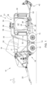
- FIG. 1 shows a schematic representation of a combination 12 of a baler 16 and a wrapper 10 according to the invention with a first embodiment of a discharge tipping device 42 according to the invention.
- the baler 16 serves to press organic material, which is picked up from a field, into a round bale and the Wrapper 10 for wrapping the round bale with film or other wrapping material.
- the combination 12 is built on a frame 14 which rests on wheels 15 on the ground.
- the baler 16 comprises a rear door 18.
- the combination 12 is pulled over a field in a forward direction V by a drawbar 20 behind a towing vehicle (farm tractor) not shown.
- the combination 12 is in the EP 1 186 225 A1 described in detail, the disclosure of which is incorporated by reference into the present documents.
- a baler 16 or a wrapper 10 could also be used independently of one another with the unloading tipping device 42, which are moved across a field with associated towing vehicles.
- the combination 12 or the baler 16 and/or the wrapper 10 could also be self-propelled.
- the baler 16 can have a receiving unit (not shown) for receiving crops and a pressing chamber 17 for forming or pressing the received crops into a round bale.
- the pressing chamber 17 can be arranged on or on the frame 14 of the baler 16, preferably connected to it and/or attached to it and/or carried.
- the wrapper 10 can be designed to wrap the round bale 22' outside the baler 16, in particular outside the pressing chamber 17.
- the wrapper 10 comprises a wrapping device 31 for wrapping the finished bale with a wrapping material, for example net or film.
- the wrapper 10 can comprise a wrapper frame, in this case designed as a support frame 38.
- the wrapper 10 comprises a pivoting device 24, which in this case is designed as a wrapping table, on which the round bale is stored.
- the pivoting device 24 can be pivoted by means of an actuator 40.
- the wrapping device 31 can comprise two wrapping arms 30.
- the finished round bale 22 can therefore be wrapped with wrapping material by the wrapping device 31 outside the pressing chamber 17 with the wrapper 10.
- the wrapped round bale 22' can roll out or down from the pivoting device 24 of the wrapper 10, in or on which the round bale lies or rests during wrapping.
- the wrapped round bale 22' can be deflected to the side using the unloading tipping device 42.
- a round bale 22 produced in the baler 16 can be moved from the baler 16 into a wrapping position in the wrapper 10 using the pivoting device 24 of the wrapper 10.
- a round bale 22' to be wrapped is thus located on the Device 24 comprising a belt 26 which runs around two rollers 28 attached to a frame 66.
- the two diametrically opposed wrapping arms 30 with vertical and horizontal sections perpendicular to each other run around the round bale 22'.
- Each vertical section of the wrapping arms 30 holds a film dispenser 32.
- the middle ends of the horizontal sections of the wrapping arms 30 are connected to a drive arrangement 34 which is designed to rotate the wrapping arms 30 about a central, vertical axis.
- the drive arrangement 34 is connected to the frame 14 by a wrapper frame, in this case designed as a support frame 38, and comprises a hydraulic motor which is connected to the hydraulic system of the towing vehicle.
- the drive assembly 34 or a separate hydraulic motor also drives the rollers 28 so that the round bale 22' rotates about its horizontal central axis while the wrapping arms 30 rotate about the round bale 22' and film is unwound from the film dispensers 32 and wrapped around the round bale 22'.
- Film holders 36 press the film against the round bale 22' during the start of the wrapping operation and cut it off after wrapping.
- the speeds of the wrapping arms 30 and the rollers 28 can be synchronized to achieve a desired positioning of the film on the round bale 22'.
- the frame 66 (see Figure 2 ) of the device 24 can be pivoted, in particular backwards and downwards, by means of the actuator 40, in particular about an axis extending horizontally and transversely to the forward direction V.
- the actuator 40 is designed as a motor (which can be connected to the device 24, for example, by a slot and a chain or a belt), which is also used to transport the movable device 24 from a front position for receiving the bale 22 from the baler 16 into the Figure 1 shown winding position in the winder 10 and also accomplishes the tilting movement. Details are given in the EP 1 186 225 A1 disclosed, the disclosure of which is incorporated by reference into these documents.
- the unloading tipping device 42 is provided.
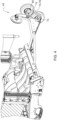
- Figure 2 shows a schematic perspective view of a winder 10 according to the invention with a second embodiment of a dumping tipping device 42 according to the invention.
- Figure 3 shows a schematic representation of the second embodiment of the unloading tipping device 42.
- Figure 6 shows a schematic detailed representation of the second embodiment of the unloading tipping device 42.
- the Figures 2 , 3 and 6 The unloading tipping device 42 and the winder 10 shown essentially correspond to the one shown in Figure 1 shown unloading tipping device 42 and the one in Figure 1 shown winder 10, so that only details and/or differences are discussed below.
- the Figure 1 Combination 12 shown can be the one in the Figures 2 , 3 and 6 shown unloading tipping device 42 and/or the winder 10 shown.
- the second embodiment will be described with reference to the Figures 2 , 3 and 6 described.
- the unloading tipping device 42 comprises a first support element 45, with which the unloading tipping device 42 can be supported on the ground.
- the unloading tipping device 42 also comprises a cross strut 64, a longitudinal strut 44, a diagonal strut 46 and a carrier plate 54, wherein the first support element 45 is connected to the carrier plate 54 and the carrier plate 54 is connected to the longitudinal strut 44.
- the longitudinal strut 44 and the diagonal strut 46 are each connected at one end to the cross strut 64 and at the other end to the carrier plate 54.
- the unloading tipping device 42 also comprises a second support element 48 and/or a spacer 55.
- the longitudinal strut 44 is designed as a tube and extends from the cross strut 64 to the rear.
- the longitudinal strut 44 comprises several sections which form angles with each other and form a horizontal "L" with a rounded middle section.
- the cross strut 64 is in turn pivotally connected at its two lateral ends by axes 56 to sections 62 of the frame 66 of the device 24, which extend backwards in a forked manner and accommodate the cross strut 64 between them.
- the obliquely arranged diagonal strut 46 extends obliquely backwards and sideways from the cross strut 64 and is connected below the rear region of the longitudinal strut 44 to a support plate 54 which extends vertically and in the forward direction V and which is in turn attached to the underside of the longitudinal strut 44.
- a first support axle 52 which holds the first support element 45 in the form of a rubber-tired wheel, is connected to or fastened to the carrier plate 54.
- a second support axle 80 (see Figure 4 ), which is the second Support element 48 in the form of a rubber-tired wheel may be connected to or fastened to the carrier plate 54 and/or a spacer 55.
- the longitudinal strut 44 has a stop at its rear, upper end, in the form of a disk 50, which is preferably attached to the longitudinal strut 44 so as to be freely rotatable about the vertical axis.
- the longitudinal strut 44 is attached to the cross strut 64 offset laterally from the longitudinal center plane of the combination 12.
- the diagonal strut 46 is spaced from the section 62 adjacent to it by approximately the same distance as the longitudinal strut 44 is from its adjacent section 62.
- the spacer 55 is connected to the carrier plate 54, in particular detachably or firmly attached thereto.
- the second support element 48 is connected or attached to the spacer 55, in particular the second support element 48 can be rotatably attached and/or mounted on the spacer 55.
- the second support axis (not shown), which holds the second support element 48 in the form of a rubber-tired wheel, is connected to the spacer 55 or attached to it.
- the spacer 55 can also be connected to the first and second support elements 45, 48, in particular the first and second support elements 45, 48 can be attached to the spacer 55.
- the spacer 55 comprises a spacer element 74 and a first and second holder 70, 72.
- a first end of the spacer element 74 is connected to the first holder 70 and a second end of the spacer element 74 is connected to the second holder 72, in particular releasably or firmly attached thereto.
- a spacer runner 76 which is designed as a runner or slide rail, is connected to the spacer element 74, in particular attached to the spacer element 74.
- the spacer 55 in particular also the spacer element 74, extend in the direction of or along the carrier plate 54.
- a round bale 22' rolling off the device 24 tipped backwards and downwards will roll on the longitudinal strut 44 and the diagonal strut 46 and will be deflected to the side by these so that it comes to rest on the field with its flat side.
- the components mentioned individually or together form deflection means which are configured to deflect a round bale 22 to the side so that it comes to rest on the ground with its flat front side.
- the second support element 48 and/or the spacer 55 are provided.
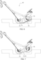
- Figure 4 shows a perspective view of a winder 10 according to the invention with a third embodiment of a discharge tipping device 42 according to the invention.
- Figure 5 shows a schematic representation of the third embodiment of the unloading tipping device 42.
- Figure 7 shows a schematic detailed representation of the third embodiment of the unloading tipping device 42.
- the Figures 4 , 5 and 7 The unloading tipping device 42 and the winder 10 shown essentially correspond to the Figures 1 to 3 and 6 shown unloading tipping devices 42 and the winders 10 shown, so that only details and/or differences are discussed below.
- the Figure 1 Combination 12 shown can be the one in the Figures 4 , 5 and 7 shown unloading tipping device 42 and/or the winder 10 shown.
- the third embodiment will be described with reference to the Figures 4 , 5 and 7 described.
- the spacer 55 comprises a runner and/or slide rail, and can in particular alternatively be designed as a runner or slide rail.
- the spacer 55 comprises a spacer element 74, which is designed as a runner 78.
- the spacer element 74 can alternatively also be designed as a slide rail.
- the spacer 55, in particular the spacer element 74 or the runner 78, extend along or in the direction of the carrier plate 54.
- the spacer 55 comprises the first and second holders 70, 72, wherein a first end of the spacer element 74 or the runner 78 is connected to the first holder 70 and a second end of the spacer element 74 is connected to the second holder 72.
- the round bale 22' is deposited by the wrapper 10.
- the wrapper 10 can also be designed as a single machine that is moved across a field independently of the baler 16. It is also possible to use a baler 16 whose baling chamber also serves to wrap the bale 22 (see WO 00/15023 A1 ), provided with a dumping device 42 according to the invention.
Landscapes
- Life Sciences & Earth Sciences (AREA)
- Environmental Sciences (AREA)
- Storage Of Harvested Produce (AREA)
Applications Claiming Priority (1)
| Application Number | Priority Date | Filing Date | Title |
|---|---|---|---|
| DE102023116715.4A DE102023116715A1 (de) | 2023-06-26 | 2023-06-26 | Abladekippvorrichtung und Ballenpresse oder Wickler |
Publications (2)
| Publication Number | Publication Date |
|---|---|
| EP4491009A1 true EP4491009A1 (fr) | 2025-01-15 |
| EP4491009B1 EP4491009B1 (fr) | 2026-03-04 |
Family
ID=91433200
Family Applications (1)
| Application Number | Title | Priority Date | Filing Date |
|---|---|---|---|
| EP24180488.9A Active EP4491009B1 (fr) | 2023-06-26 | 2024-06-06 | Dispositif de basculement de déchargement et presse à balles ou enrouleur |
Country Status (3)
| Country | Link |
|---|---|
| US (1) | US20240423137A1 (fr) |
| EP (1) | EP4491009B1 (fr) |
| DE (1) | DE102023116715A1 (fr) |
Citations (11)
| Publication number | Priority date | Publication date | Assignee | Title |
|---|---|---|---|---|
| US4162135A (en) | 1977-12-01 | 1979-07-24 | Sperry Rand Corporation | Quarter bale turning apparatus |
| DE4138499A1 (de) | 1991-11-22 | 1993-05-27 | Busatis Werke Kg | Rundballenwickelgeraet |
| GB2305648A (en) | 1995-09-29 | 1997-04-16 | Wellmount Ltd | A bale Wrapping apparatus |
| EP0910941A1 (fr) | 1997-09-29 | 1999-04-28 | Agri Patents Limited | Ameliorations à et en relation avec des envelopeurs de balles |
| WO2000015023A1 (fr) | 1998-09-15 | 2000-03-23 | Viviane Bertrand | Presse a balles rondes avec enrubanneuse integree |
| JP3101618B1 (ja) | 1999-09-22 | 2000-10-23 | 花野商事株式会社 | 粉体離型剤の塗布方法 |
| EP1186225A1 (fr) | 2000-09-07 | 2002-03-13 | Deere & Company | Combinaison d'une presse, une enrubanneuse, et un châssis pour l'attachement des deux éléments |
| EP2149293A1 (fr) | 2008-07-31 | 2010-02-03 | Deere & Company | Combinaison de ramasseuse-presse et d'emballeuse |
| EP2606714A1 (fr) * | 2011-12-22 | 2013-06-26 | Maschinenfabrik Bernard Krone GmbH | Dispositif d'enveloppement de balles rondes |
| EP3338534A1 (fr) * | 2016-12-20 | 2018-06-27 | Usines Claas France S.A.S | Presse à balles rondes |
| EP4245121A1 (fr) * | 2022-03-14 | 2023-09-20 | Deere & Company | Dispositif pour basculer le déchargement de balles rondes |
-
2023
- 2023-06-26 DE DE102023116715.4A patent/DE102023116715A1/de active Pending
-
2024
- 2024-04-22 US US18/641,548 patent/US20240423137A1/en active Pending
- 2024-06-06 EP EP24180488.9A patent/EP4491009B1/fr active Active
Patent Citations (11)
| Publication number | Priority date | Publication date | Assignee | Title |
|---|---|---|---|---|
| US4162135A (en) | 1977-12-01 | 1979-07-24 | Sperry Rand Corporation | Quarter bale turning apparatus |
| DE4138499A1 (de) | 1991-11-22 | 1993-05-27 | Busatis Werke Kg | Rundballenwickelgeraet |
| GB2305648A (en) | 1995-09-29 | 1997-04-16 | Wellmount Ltd | A bale Wrapping apparatus |
| EP0910941A1 (fr) | 1997-09-29 | 1999-04-28 | Agri Patents Limited | Ameliorations à et en relation avec des envelopeurs de balles |
| WO2000015023A1 (fr) | 1998-09-15 | 2000-03-23 | Viviane Bertrand | Presse a balles rondes avec enrubanneuse integree |
| JP3101618B1 (ja) | 1999-09-22 | 2000-10-23 | 花野商事株式会社 | 粉体離型剤の塗布方法 |
| EP1186225A1 (fr) | 2000-09-07 | 2002-03-13 | Deere & Company | Combinaison d'une presse, une enrubanneuse, et un châssis pour l'attachement des deux éléments |
| EP2149293A1 (fr) | 2008-07-31 | 2010-02-03 | Deere & Company | Combinaison de ramasseuse-presse et d'emballeuse |
| EP2606714A1 (fr) * | 2011-12-22 | 2013-06-26 | Maschinenfabrik Bernard Krone GmbH | Dispositif d'enveloppement de balles rondes |
| EP3338534A1 (fr) * | 2016-12-20 | 2018-06-27 | Usines Claas France S.A.S | Presse à balles rondes |
| EP4245121A1 (fr) * | 2022-03-14 | 2023-09-20 | Deere & Company | Dispositif pour basculer le déchargement de balles rondes |
Also Published As
| Publication number | Publication date |
|---|---|
| US20240423137A1 (en) | 2024-12-26 |
| DE102023116715A1 (de) | 2025-01-02 |
| EP4491009B1 (fr) | 2026-03-04 |
Similar Documents
| Publication | Publication Date | Title |
|---|---|---|
| EP0543145B1 (fr) | Dispositif pour emballer des balles rondes | |
| EP0983720B1 (fr) | Dispositif pour emballer des balles rondes | |
| EP1210862B1 (fr) | Presse et appareil pour envelopper des balles rondes | |
| EP3078256B1 (fr) | Chariot de recolte comprenant un appareil de dosage et d'epandage | |
| EP3578035B1 (fr) | Presse à balles rondes et procédé de déchargement | |
| DE102007018329A1 (de) | Kontinuierlich arbeitende Ballenpresse | |
| EP2878190B1 (fr) | Presse à balles rondes agricole | |
| DE102008001779B4 (de) | Erntevorsatz mit einem Gutaufnehmer und einer Querförderschnecke | |
| EP1618777B1 (fr) | Dispositif de décharge d'une récolteuse agricole | |
| EP4245121B1 (fr) | Dispositif pour basculer le déchargement de balles rondes | |
| EP4491009B1 (fr) | Dispositif de basculement de déchargement et presse à balles ou enrouleur | |
| DE102016124902A1 (de) | Rundballenpresse | |
| AT520228B1 (de) | Ballentransportwagen | |
| EP4176705A1 (fr) | Presse à balles rondes avec un dispositif pour serrer une balle | |
| EP1588601B1 (fr) | Machine de récolte avec un dispositif de décharge | |
| EP2853145B1 (fr) | Presse à balles rondes | |
| DE102022105847A1 (de) | Schwadaufnehmer mit drittem Stützrad | |
| WO2016118986A1 (fr) | Dispositif pour le chargement et le transport de ballots ronds | |
| EP0424753B1 (fr) | Machine à récolter les tubercules, en particulier les betteraves sucrières | |
| DE2316616C2 (de) | Ballenladewagen | |
| EP4295663A1 (fr) | Dispositif de ramassage de balles pour recevoir des balles rondes d'une presse à balles rondes | |
| AT233467B (de) | Verfahren und Maschine zum Aufladen, Verteilen und Pressen von Massengütern auf der Ladefläche von Fahrzeugen | |
| WO2024227476A1 (fr) | Accessoire de cueillette pliable pour machine de récolte | |
| DE1301168B (de) | Selbstfahrender Ladewagen |
Legal Events
| Date | Code | Title | Description |
|---|---|---|---|
| PUAI | Public reference made under article 153(3) epc to a published international application that has entered the european phase |
Free format text: ORIGINAL CODE: 0009012 |
|
| STAA | Information on the status of an ep patent application or granted ep patent |
Free format text: STATUS: THE APPLICATION HAS BEEN PUBLISHED |
|
| AK | Designated contracting states |
Kind code of ref document: A1 Designated state(s): AL AT BE BG CH CY CZ DE DK EE ES FI FR GB GR HR HU IE IS IT LI LT LU LV MC ME MK MT NL NO PL PT RO RS SE SI SK SM TR |
|
| STAA | Information on the status of an ep patent application or granted ep patent |
Free format text: STATUS: REQUEST FOR EXAMINATION WAS MADE |
|
| 17P | Request for examination filed |
Effective date: 20250715 |
|
| STAA | Information on the status of an ep patent application or granted ep patent |
Free format text: STATUS: EXAMINATION IS IN PROGRESS |
|
| 17Q | First examination report despatched |
Effective date: 20250902 |
|
| GRAP | Despatch of communication of intention to grant a patent |
Free format text: ORIGINAL CODE: EPIDOSNIGR1 |
|
| STAA | Information on the status of an ep patent application or granted ep patent |
Free format text: STATUS: GRANT OF PATENT IS INTENDED |
|
| INTG | Intention to grant announced |
Effective date: 20251126 |
|
| RIN1 | Information on inventor provided before grant (corrected) |
Inventor name: CHAPON, EMMANUEL Inventor name: BLANCHON, GUILLAUME |
|
| GRAS | Grant fee paid |
Free format text: ORIGINAL CODE: EPIDOSNIGR3 |
|
| GRAA | (expected) grant |
Free format text: ORIGINAL CODE: 0009210 |
|
| STAA | Information on the status of an ep patent application or granted ep patent |
Free format text: STATUS: THE PATENT HAS BEEN GRANTED |
|
| AK | Designated contracting states |
Kind code of ref document: B1 Designated state(s): AL AT BE BG CH CY CZ DE DK EE ES FI FR GB GR HR HU IE IS IT LI LT LU LV MC ME MK MT NL NO PL PT RO RS SE SI SK SM TR |
|
| REG | Reference to a national code |
Ref country code: CH Ref legal event code: F10 Free format text: ST27 STATUS EVENT CODE: U-0-0-F10-F00 (AS PROVIDED BY THE NATIONAL OFFICE) Effective date: 20260304 Ref country code: GB Ref legal event code: FG4D Free format text: NOT ENGLISH |
|
| REG | Reference to a national code |
Ref country code: DE Ref legal event code: R096 Ref document number: 502024000820 Country of ref document: DE |
|
| REG | Reference to a national code |
Ref country code: IE Ref legal event code: FG4D Free format text: LANGUAGE OF EP DOCUMENT: GERMAN |