EP4491105A2 - Système et procédé de synchronisation de signaux biopotentiels - Google Patents
Système et procédé de synchronisation de signaux biopotentiels Download PDFInfo
- Publication number
- EP4491105A2 EP4491105A2 EP24183586.7A EP24183586A EP4491105A2 EP 4491105 A2 EP4491105 A2 EP 4491105A2 EP 24183586 A EP24183586 A EP 24183586A EP 4491105 A2 EP4491105 A2 EP 4491105A2
- Authority
- EP
- European Patent Office
- Prior art keywords
- signals
- digitized
- ecg
- signal
- sampling
- Prior art date
- Legal status (The legal status is an assumption and is not a legal conclusion. Google has not performed a legal analysis and makes no representation as to the accuracy of the status listed.)
- Pending
Links
Images


Classifications
-
- A—HUMAN NECESSITIES
- A61—MEDICAL OR VETERINARY SCIENCE; HYGIENE
- A61B—DIAGNOSIS; SURGERY; IDENTIFICATION
- A61B5/00—Measuring for diagnostic purposes; Identification of persons
- A61B5/24—Detecting, measuring or recording bioelectric or biomagnetic signals of the body or parts thereof
- A61B5/25—Bioelectric electrodes therefor
- A61B5/279—Bioelectric electrodes therefor specially adapted for particular uses
- A61B5/28—Bioelectric electrodes therefor specially adapted for particular uses for electrocardiography [ECG]
-
- A—HUMAN NECESSITIES
- A61—MEDICAL OR VETERINARY SCIENCE; HYGIENE
- A61B—DIAGNOSIS; SURGERY; IDENTIFICATION
- A61B5/00—Measuring for diagnostic purposes; Identification of persons
- A61B5/72—Signal processing specially adapted for physiological signals or for diagnostic purposes
- A61B5/7271—Specific aspects of physiological measurement analysis
- A61B5/7285—Specific aspects of physiological measurement analysis for synchronizing or triggering a physiological measurement or image acquisition with a physiological event or waveform, e.g. an ECG signal
-
- A—HUMAN NECESSITIES
- A61—MEDICAL OR VETERINARY SCIENCE; HYGIENE
- A61B—DIAGNOSIS; SURGERY; IDENTIFICATION
- A61B5/00—Measuring for diagnostic purposes; Identification of persons
- A61B5/0002—Remote monitoring of patients using telemetry, e.g. transmission of vital signals via a communication network
- A61B5/0004—Remote monitoring of patients using telemetry, e.g. transmission of vital signals via a communication network characterised by the type of physiological signal transmitted
- A61B5/0006—ECG or EEG signals
-
- A—HUMAN NECESSITIES
- A61—MEDICAL OR VETERINARY SCIENCE; HYGIENE
- A61B—DIAGNOSIS; SURGERY; IDENTIFICATION
- A61B18/00—Surgical instruments, devices or methods for transferring non-mechanical forms of energy to or from the body
-
- A—HUMAN NECESSITIES
- A61—MEDICAL OR VETERINARY SCIENCE; HYGIENE
- A61B—DIAGNOSIS; SURGERY; IDENTIFICATION
- A61B18/00—Surgical instruments, devices or methods for transferring non-mechanical forms of energy to or from the body
- A61B18/04—Surgical instruments, devices or methods for transferring non-mechanical forms of energy to or from the body by heating
- A61B18/12—Surgical instruments, devices or methods for transferring non-mechanical forms of energy to or from the body by heating by passing a current through the tissue to be heated, e.g. high-frequency current
- A61B18/14—Probes or electrodes therefor
- A61B18/1492—Probes or electrodes therefor having a flexible, catheter-like structure, e.g. for heart ablation
-
- A—HUMAN NECESSITIES
- A61—MEDICAL OR VETERINARY SCIENCE; HYGIENE
- A61B—DIAGNOSIS; SURGERY; IDENTIFICATION
- A61B5/00—Measuring for diagnostic purposes; Identification of persons
- A61B5/24—Detecting, measuring or recording bioelectric or biomagnetic signals of the body or parts thereof
- A61B5/25—Bioelectric electrodes therefor
- A61B5/279—Bioelectric electrodes therefor specially adapted for particular uses
- A61B5/28—Bioelectric electrodes therefor specially adapted for particular uses for electrocardiography [ECG]
- A61B5/282—Holders for multiple electrodes
-
- A—HUMAN NECESSITIES
- A61—MEDICAL OR VETERINARY SCIENCE; HYGIENE
- A61B—DIAGNOSIS; SURGERY; IDENTIFICATION
- A61B5/00—Measuring for diagnostic purposes; Identification of persons
- A61B5/24—Detecting, measuring or recording bioelectric or biomagnetic signals of the body or parts thereof
- A61B5/25—Bioelectric electrodes therefor
- A61B5/279—Bioelectric electrodes therefor specially adapted for particular uses
- A61B5/28—Bioelectric electrodes therefor specially adapted for particular uses for electrocardiography [ECG]
- A61B5/283—Invasive
-
- A—HUMAN NECESSITIES
- A61—MEDICAL OR VETERINARY SCIENCE; HYGIENE
- A61B—DIAGNOSIS; SURGERY; IDENTIFICATION
- A61B5/00—Measuring for diagnostic purposes; Identification of persons
- A61B5/24—Detecting, measuring or recording bioelectric or biomagnetic signals of the body or parts thereof
- A61B5/25—Bioelectric electrodes therefor
- A61B5/279—Bioelectric electrodes therefor specially adapted for particular uses
- A61B5/28—Bioelectric electrodes therefor specially adapted for particular uses for electrocardiography [ECG]
- A61B5/283—Invasive
- A61B5/287—Holders for multiple electrodes, e.g. electrode catheters for electrophysiological study [EPS]
-
- A—HUMAN NECESSITIES
- A61—MEDICAL OR VETERINARY SCIENCE; HYGIENE
- A61B—DIAGNOSIS; SURGERY; IDENTIFICATION
- A61B5/00—Measuring for diagnostic purposes; Identification of persons
- A61B5/24—Detecting, measuring or recording bioelectric or biomagnetic signals of the body or parts thereof
- A61B5/316—Modalities, i.e. specific diagnostic methods
- A61B5/318—Heart-related electrical modalities, e.g. electrocardiography [ECG]
-
- A—HUMAN NECESSITIES
- A61—MEDICAL OR VETERINARY SCIENCE; HYGIENE
- A61B—DIAGNOSIS; SURGERY; IDENTIFICATION
- A61B5/00—Measuring for diagnostic purposes; Identification of persons
- A61B5/24—Detecting, measuring or recording bioelectric or biomagnetic signals of the body or parts thereof
- A61B5/316—Modalities, i.e. specific diagnostic methods
- A61B5/318—Heart-related electrical modalities, e.g. electrocardiography [ECG]
- A61B5/321—Accessories or supplementary instruments therefor, e.g. cord hangers
-
- A—HUMAN NECESSITIES
- A61—MEDICAL OR VETERINARY SCIENCE; HYGIENE
- A61B—DIAGNOSIS; SURGERY; IDENTIFICATION
- A61B5/00—Measuring for diagnostic purposes; Identification of persons
- A61B5/24—Detecting, measuring or recording bioelectric or biomagnetic signals of the body or parts thereof
- A61B5/316—Modalities, i.e. specific diagnostic methods
- A61B5/318—Heart-related electrical modalities, e.g. electrocardiography [ECG]
- A61B5/33—Heart-related electrical modalities, e.g. electrocardiography [ECG] specially adapted for cooperation with other devices
-
- A—HUMAN NECESSITIES
- A61—MEDICAL OR VETERINARY SCIENCE; HYGIENE
- A61B—DIAGNOSIS; SURGERY; IDENTIFICATION
- A61B5/00—Measuring for diagnostic purposes; Identification of persons
- A61B5/24—Detecting, measuring or recording bioelectric or biomagnetic signals of the body or parts thereof
- A61B5/316—Modalities, i.e. specific diagnostic methods
- A61B5/318—Heart-related electrical modalities, e.g. electrocardiography [ECG]
- A61B5/339—Displays specially adapted therefor
-
- A—HUMAN NECESSITIES
- A61—MEDICAL OR VETERINARY SCIENCE; HYGIENE
- A61B—DIAGNOSIS; SURGERY; IDENTIFICATION
- A61B5/00—Measuring for diagnostic purposes; Identification of persons
- A61B5/24—Detecting, measuring or recording bioelectric or biomagnetic signals of the body or parts thereof
- A61B5/316—Modalities, i.e. specific diagnostic methods
- A61B5/318—Heart-related electrical modalities, e.g. electrocardiography [ECG]
- A61B5/346—Analysis of electrocardiograms
-
- A—HUMAN NECESSITIES
- A61—MEDICAL OR VETERINARY SCIENCE; HYGIENE
- A61B—DIAGNOSIS; SURGERY; IDENTIFICATION
- A61B5/00—Measuring for diagnostic purposes; Identification of persons
- A61B5/24—Detecting, measuring or recording bioelectric or biomagnetic signals of the body or parts thereof
- A61B5/316—Modalities, i.e. specific diagnostic methods
- A61B5/318—Heart-related electrical modalities, e.g. electrocardiography [ECG]
- A61B5/367—Electrophysiological study [EPS], e.g. electrical activation mapping or electro-anatomical mapping
-
- A—HUMAN NECESSITIES
- A61—MEDICAL OR VETERINARY SCIENCE; HYGIENE
- A61B—DIAGNOSIS; SURGERY; IDENTIFICATION
- A61B5/00—Measuring for diagnostic purposes; Identification of persons
- A61B5/68—Arrangements of detecting, measuring or recording means, e.g. sensors, in relation to patient
- A61B5/6846—Arrangements of detecting, measuring or recording means, e.g. sensors, in relation to patient specially adapted to be brought in contact with an internal body part, i.e. invasive
- A61B5/6847—Arrangements of detecting, measuring or recording means, e.g. sensors, in relation to patient specially adapted to be brought in contact with an internal body part, i.e. invasive mounted on an invasive device
- A61B5/6852—Catheters
-
- A—HUMAN NECESSITIES
- A61—MEDICAL OR VETERINARY SCIENCE; HYGIENE
- A61B—DIAGNOSIS; SURGERY; IDENTIFICATION
- A61B5/00—Measuring for diagnostic purposes; Identification of persons
- A61B5/68—Arrangements of detecting, measuring or recording means, e.g. sensors, in relation to patient
- A61B5/6846—Arrangements of detecting, measuring or recording means, e.g. sensors, in relation to patient specially adapted to be brought in contact with an internal body part, i.e. invasive
- A61B5/6847—Arrangements of detecting, measuring or recording means, e.g. sensors, in relation to patient specially adapted to be brought in contact with an internal body part, i.e. invasive mounted on an invasive device
- A61B5/6852—Catheters
- A61B5/6859—Catheters with multiple distal splines
-
- A—HUMAN NECESSITIES
- A61—MEDICAL OR VETERINARY SCIENCE; HYGIENE
- A61B—DIAGNOSIS; SURGERY; IDENTIFICATION
- A61B5/00—Measuring for diagnostic purposes; Identification of persons
- A61B5/74—Details of notification to user or communication with user or patient; User input means
- A61B5/742—Details of notification to user or communication with user or patient; User input means using visual displays
-
- G—PHYSICS
- G16—INFORMATION AND COMMUNICATION TECHNOLOGY [ICT] SPECIALLY ADAPTED FOR SPECIFIC APPLICATION FIELDS
- G16H—HEALTHCARE INFORMATICS, i.e. INFORMATION AND COMMUNICATION TECHNOLOGY [ICT] SPECIALLY ADAPTED FOR THE HANDLING OR PROCESSING OF MEDICAL OR HEALTHCARE DATA
- G16H20/00—ICT specially adapted for therapies or health-improving plans, e.g. for handling prescriptions, for steering therapy or for monitoring patient compliance
- G16H20/30—ICT specially adapted for therapies or health-improving plans, e.g. for handling prescriptions, for steering therapy or for monitoring patient compliance relating to physical therapies or activities, e.g. physiotherapy, acupressure or exercising
-
- G—PHYSICS
- G16—INFORMATION AND COMMUNICATION TECHNOLOGY [ICT] SPECIALLY ADAPTED FOR SPECIFIC APPLICATION FIELDS
- G16H—HEALTHCARE INFORMATICS, i.e. INFORMATION AND COMMUNICATION TECHNOLOGY [ICT] SPECIALLY ADAPTED FOR THE HANDLING OR PROCESSING OF MEDICAL OR HEALTHCARE DATA
- G16H50/00—ICT specially adapted for medical diagnosis, medical simulation or medical data mining; ICT specially adapted for detecting, monitoring or modelling epidemics or pandemics
- G16H50/30—ICT specially adapted for medical diagnosis, medical simulation or medical data mining; ICT specially adapted for detecting, monitoring or modelling epidemics or pandemics for calculating health indices; for individual health risk assessment
-
- A—HUMAN NECESSITIES
- A61—MEDICAL OR VETERINARY SCIENCE; HYGIENE
- A61B—DIAGNOSIS; SURGERY; IDENTIFICATION
- A61B18/00—Surgical instruments, devices or methods for transferring non-mechanical forms of energy to or from the body
- A61B2018/00315—Surgical instruments, devices or methods for transferring non-mechanical forms of energy to or from the body for treatment of particular body parts
- A61B2018/00345—Vascular system
- A61B2018/00351—Heart
- A61B2018/00357—Endocardium
-
- A—HUMAN NECESSITIES
- A61—MEDICAL OR VETERINARY SCIENCE; HYGIENE
- A61B—DIAGNOSIS; SURGERY; IDENTIFICATION
- A61B18/00—Surgical instruments, devices or methods for transferring non-mechanical forms of energy to or from the body
- A61B2018/00571—Surgical instruments, devices or methods for transferring non-mechanical forms of energy to or from the body for achieving a particular surgical effect
- A61B2018/00577—Ablation
-
- A—HUMAN NECESSITIES
- A61—MEDICAL OR VETERINARY SCIENCE; HYGIENE
- A61B—DIAGNOSIS; SURGERY; IDENTIFICATION
- A61B18/00—Surgical instruments, devices or methods for transferring non-mechanical forms of energy to or from the body
- A61B2018/00571—Surgical instruments, devices or methods for transferring non-mechanical forms of energy to or from the body for achieving a particular surgical effect
- A61B2018/00613—Irreversible electroporation
-
- A—HUMAN NECESSITIES
- A61—MEDICAL OR VETERINARY SCIENCE; HYGIENE
- A61B—DIAGNOSIS; SURGERY; IDENTIFICATION
- A61B5/00—Measuring for diagnostic purposes; Identification of persons
- A61B5/24—Detecting, measuring or recording bioelectric or biomagnetic signals of the body or parts thereof
- A61B5/25—Bioelectric electrodes therefor
- A61B5/251—Means for maintaining electrode contact with the body
- A61B5/257—Means for maintaining electrode contact with the body using adhesive means, e.g. adhesive pads or tapes
-
- G—PHYSICS
- G16—INFORMATION AND COMMUNICATION TECHNOLOGY [ICT] SPECIALLY ADAPTED FOR SPECIFIC APPLICATION FIELDS
- G16H—HEALTHCARE INFORMATICS, i.e. INFORMATION AND COMMUNICATION TECHNOLOGY [ICT] SPECIALLY ADAPTED FOR THE HANDLING OR PROCESSING OF MEDICAL OR HEALTHCARE DATA
- G16H40/00—ICT specially adapted for the management or administration of healthcare resources or facilities; ICT specially adapted for the management or operation of medical equipment or devices
- G16H40/60—ICT specially adapted for the management or administration of healthcare resources or facilities; ICT specially adapted for the management or operation of medical equipment or devices for the operation of medical equipment or devices
- G16H40/63—ICT specially adapted for the management or administration of healthcare resources or facilities; ICT specially adapted for the management or operation of medical equipment or devices for the operation of medical equipment or devices for local operation
Definitions
- the present invention is in the field signal processing of physiological signals and particularly relates to synchronization of biopotential signals such as electrocardiogram (ECG) electrograms (EGM) and intracardiac-electrograms (IEGM) used in electrocardiographic monitoring during medical procedures.
- ECG electrocardiogram
- EGM intracardiac-electrograms
- a wide range of medical procedures involve placing probes, such as catheters, within a patient's body.
- probes such as catheters
- One medical procedure in which these types of probes or catheters have proved extremely useful is in the treatment of cardiac arrhythmias.
- Cardiac arrhythmias and atrial fibrillation in particular, persist as common and dangerous medical ailments, especially in the aging population.
- Diagnosis and treatment of cardiac arrhythmias include mapping the electrical properties of heart tissue, especially the endocardium and the heart volume, and selectively ablating cardiac tissue by application of energy.
- Catheters are inserted into the heart chamber and optionally around the heart chamber during such procedures. In most procedures, multiple catheters are inserted into the patient. Catheters may include mapping, ablation, temperature sensing and image sensing catheters. Some catheters are dedicated for placement in specific parts of the anatomy, e.g., coronary sinus, esophagus, atrium, ventricle. The catheters have multiple electrical channels, some more than others depending on the number of sensors and electrodes included in each catheter. The number and type of catheters depends on the procedure and on the physician preferred workflow. During a procedure, the electrical activity of the heart is monitored from the catheter electrodes and sensors as well as from body surface electrodes attached to the patient's skin.
- some diagnostic catheters include a distal end with 50 or more biopotential sensors (e.g., electrodes) for sensing electrical activity within a chamber of the heart.
- biopotential sensors e.g., electrodes
- the large number of electrodes enables a physician to simultaneously capture the electrical activity from multiple locations in the heart chamber.
- a position sensor on the catheter records locations at which the electrical activity was sampled.
- the electrodes on the distal end include electrodes that are configured to engage with the tissue wall of the heart and sense near field biopotential signals and may also include a reference electrode configured to be immersed in the blood pool and sense far-field biopotential signal(s).
- the far-field signal may be used to remove any far field components that may be captured by the electrodes that are configured to engage with the tissue wall of the heart and sense near field signals.
- the existing/deployed hardware which is generally adapted to collect, sample, and further communicated biopotential signals (ECG) from body surface electrodes as well as other catheters, is generally not suited for additionally collecting and sampling and communicating the additional sensory signals obtained from the high-density catheter(s).
- ECG biopotential signals
- Mere addition of conventional hardware for collecting, sampling and/or communicating the signals from the HD catheters does not facilitate synchronized sampling and/or communication of the signals from the HD catheters together with the signals from the other electrophysiological equipment.
- the present invention thus provides novel systems and methods for solving these problems to enable streaming of the biopotential signals obtained from HD catheters in synchronization with the biopotential signals obtained from other electrophysiological equipment such as the body surface electrodes and other catheters.
- the invention facilitates achieving such synchronized streaming while without a need to replace the existing medical devices (e.g. which are already deployed), thus enabling to incorporate use of HD catheters in existing medical facilities in cost effective manner.
- sample synchronization between the signals sampled by the existing and added hardware may be achieved by utilizing the output from one of the sensors of the HD catheter (which is herein after also referred to as reference analog signal) for synchronizing the between the sensory signals obtained from the HD catheter and the sensory signals obtained from the other electrophysiological equipment.
- the reference analog signal is split and provided for sampling by both existing and added hardware thereby yielding two digital reference signals presenting the sampling of the reference analog signal according to the sampling clocks of the respective existing and added hardware. Indeed, as these samplings may not be synchronized, extra sample(s) may be included in any one of the two digital reference signals for a given time period due to difference in sampling clocks by which they are sampled.
- the two digital reference signals are sampled from a common reference analog signal, such extra sample(s) can be identified by comparison of the two digital reference signals.
- the identified extra sample(s) are then removed from the respective digital signals at which they exist thus synchronizing the samples of the digital signals sampled by the two sampling utilities and enabling their synchronized streaming to the display.
- the comparison between the digital reference signals may be performed often enough to identify and remove a single extra sample or only a few extra samples (e.g. up to 3) at each time, so as to maintain the continuous synchronization between the digital signals while avoiding apparent information gap in the displayed signals.
- signal which is selected for use as the reference analog signal for the synchronization should satisfy certain prerequisites as follows: it should be continuously non-stationary (e.g. continuously having non-constant value); and it should be non-periodic at least for the duration of each of the time intervals at which the comparison is performed to identify the extra sample(s) between the 1 st and 2 nd digital reference signals.
- the far-field biopotential signal (e.g. far-field IEGM obtained from an HD catheter) satisfies these prerequisites for and is suitable for use as reference signal for the synchronization. This is because: 1.
- the far field biopotential signal is always present during the medical procedure, as opposed for example to near field signals that will only be captured based on touch or proximity of the electrodes to the tissue (e.g. skin/heart-wall).
- the far field biopotential signal is a biological signal and therefore not periodic. Accordingly in certain embodiments of the present invention the a far-field biopotential signal (e.g. obtained from a far-field IEGM sensor of an HD catheter) is specifically selected as the reference analog signal used for the synchronization process which is described above and in more detail below.
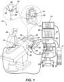
- System 10 includes multiple catheters, which are percutaneously inserted by a physician 24 through the patient's vascular system into a chamber or vascular structure of a heart 12.
- a delivery sheath catheter is inserted into the left or right atrium near a desired location in heart 12.
- one or more catheters may be inserted into the delivery sheath catheter so as to arrive at the desired location in heart 12.
- the plurality of catheters may include catheters dedicated for sensing Intracardiac Electrogram (IEGM) signals, catheters dedicated for ablating and/or catheters dedicated for both sensing and ablating.
- An example catheter 14, that is configured for sensing IEGM is illustrated herein.
- Physician 24 may place a distal tip 28 of catheter 14 in contact with the heart wall for sensing a target site in heart 12.
- physician 24 may similarly place a distal end of an ablation catheter in contact with a target site for ablating tissue.
- Catheter 14 is an exemplary catheter that includes one and preferably multiple electrodes 26 optionally distributed over a plurality of splines 22 at distal tip 28 and configured to sense the IEGM signals.
- Catheter 14 may additionally include a position sensor 29 embedded in or near distal tip 28 for tracking position and orientation of distal tip 28.
- position sensor 29 is a magnetic based position sensor including three magnetic coils for sensing three-dimensional (3D) position and orientation.
- Magnetic based position sensor 29 may be operated together with a location pad 25 including a plurality of magnetic coils 32 configured to generate magnetic fields in a predefined working volume. Real time position of distal tip 28 of catheter 14 may be tracked based on magnetic fields generated with location pad 25 and sensed by magnetic based position sensor 29. Details of the magnetic based position sensing technology are described in U.S. Patent Nos. 5,5391,199 ; 5,443,489 ; 5,558,091 ; 6,172,499 ; 6,239,724 ; 6,332,089 ; 6,484,118 ; 6,618,612 ; 6,690,963 ; 6,788,967 ; 6,892,091 .
- System 10 includes one or more electrode patches 38 positioned for skin contact on patient 23 to establish location reference for location pad 25 as well as impedance-based tracking of electrodes 26.
- impedance-based tracking electrical current is directed to electrodes 26 and sensed at electrode skin patches 38 so that the location of each electrode can be triangulated via the electrode patches 38. Details of the impedance-based location tracking technology are described in US Patent Nos. 7,536,218 ; 7,756,576 ; 7,848,787 ; 7,869,865 ; and 8,456,182 .
- a recorder 11 records and displays electrograms 21 captured with body surface electrocardiogram (ECG) electrodes 18 and intracardiac electrograms (IEGM) captured with electrodes 26 of catheter 14.
- ECG body surface electrocardiogram
- IEGM intracardiac electrograms
- Recorder 11 may include pacing capability for pacing the heart rhythm and/or may be electrically connected to a standalone pacer.
- System 10 may include an ablation energy generator 50 that is adapted to conduct ablative energy to one or more of electrodes at a distal tip of a catheter configured for ablating.
- Energy produced by ablation energy generator 50 may include, but is not limited to, radiofrequency (RF) energy or pulsed-field ablation (PFA) energy, including monopolar or bipolar high-voltage DC pulses as may be used to effect irreversible electroporation (IRE), or combinations thereof.
- RF radiofrequency
- PFA pulsed-field ablation
- IRE irreversible electroporation
- Patient interface unit (PIU) 30 is an interface configured to establish electrical communication between medical devices, such as catheters and/or other electrophysiological equipment, and a workstation 55 for controlling operation of system 10.
- the medical devices of system 10 include may include for example electrophysiological equipment such as one or more catheters, location pad 25, body surface ECG electrodes 18, electrode patches 38, ablation energy generator 50, and recorder 11.
- PIU 30 additionally includes processing capability for implementing real-time computations of location of the catheters and for performing ECG calculations.
- Workstation 55 includes memory, processor unit with memory or storage with appropriate operating software stored therein, and user interface capability. Workstation 55 may provide multiple functions, optionally including (1) modeling the endocardial anatomy in three-dimensions (3D) and rendering the model or anatomical map for display on a display device 27, (2) displaying on display device 27 activation sequences 20 (or other data) compiled from recorded electrograms 21 in representative visual indicia or imagery superimposed on the rendered anatomical map, (3) displaying real-time location and orientation of multiple catheters within the heart chamber, and (4) displaying on display device 27 sites of interest such as places where ablation energy has been applied.
- One commercial product embodying elements of the system 10 is available as the CARTO TM 3 System, available from Biosense Webster, Inc., 31A Technology Drive, Irvine, CA 92618.
- catheter 14 is a high density (HD) catheter 14 having for example 50 or more biopotential sensors (ECG electrodes).
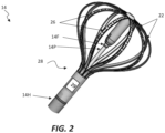
- An example of such high-density catheter 14 is schematically illustrated in Fig. 2 .
- the HD catheter 14 includes a shaft 14H with a position sensor 29 typically embedded in or near distal end 28 of the shaft 14H for tracking position and orientation of distal tip 28.
- the HD catheter 14 in this particular non-limiting example includes a pusher rode 14P passing through the shaft 14H and a plurality of splines 22 with multitudes of near-field intracardial electrogram sensors/electrodes 26 arranged thereon.
- the splines 22 are arranged near the distal end and form and expandable distal end assembly that can be deflectable outwardly from the catheter by moving the pusher rode 14P to thereby engage the near-field intracardial electrogram sensors/electrodes 26 in to contact with the tissue wall of the heart for sensing near-field signals IEGM signals (e.g. activation biopotential signals) when the catheter is located intracardially.
- the catheter 14 also includes a far-field intracardial electrogram sensor/electrode 14F (in this example arranged on the pusher rode 14P).
- the far-field IEGM sensor/electrode 14F is configured to be maintained spaced from the intracardial tissues during operation of the catheter, while being be immersed in the blood pool to measure/sense far-field biopotential signal (far-field IEGM). To this end the far-field IEGM sensor/electrode 14F is typically larger than the near-field electrodes 26 and configured with sufficient sensitivity for sensing the far-field IEGM signals. The far-field signal may be used for example in order to remove far field components that may be captured by the near-field electrodes 26.
- biopotential signal/sensor is used herein to designate electrical physiological signals or sensors thereof, such as and not limited to electrocardiograms (ECG), electrograms (EGM) and intracardiac electrograms (IEGM).
- ECG electrocardiograms
- EGM electrograms
- IEGM intracardiac electrograms
- ECG electrocardiograms
- far-field with reference to biopotential signal is used herein to designate a biopotential signal, such as ECG, EGM and IEGM, that is measured by a suitable far-field sensor/electrode without contact with a body tissue of the patient (e.g.
- near-field is used herein with reference to biopotential signal to that are measured by sensors/electrodes designed to contact a body tissue of the patient (e.g. skin tissue or intracardiac tissue) for conducting the measurement.
- the electrophysiological equipment such as the surface ECG device 38 which includes a plurality of ECG electrode patches attached externally to the patient's body/skin, as well as other electrophysiological equipment such as additional catheters (not specifically shown) are connected to the PIU 30 which facilitate electrical communication between these electrophysiological equipment and the workstation 55.
- the PIU 30 may be for example adapted to apply analog to digital conversion (sampling) to the signals received from the electrophysiological equipment connected thereto, and/or pack these signals in data packets and communicate them to the workstation 55.
- the PIU 30 may have limited channels for collecting and simultaneously sampling/packing sensory signals and cannot accommodate the multitude of sensory channels provided by the multitude of electrodes 26 of an HD catheter 14 such as that exemplified in Fig. 2 .
- system 10 includes an additional signal processing unit (SPU) 31 which is configured and operable for complementing/extending the functionality of the PIU 30 to enable connection of additional medical devices, such as HD catheter 14, to the system 10.
- the SPU 31 is configured and operable to have one or more functionalities similar to those of the PIU 30 described above (not necessarily all the PIS functionality), so as to complement the PIU 30 and supporting the connection of additional medical devices, to the system 10.
- SPU 31 provide interface for collecting and sampling/packing the signals from the HD catheter 14 or other electrophysiological equipment, and possibly also for connecting such electrophysiological equipment to the ablation energy generator 50, and/or recorder 11.
- the SPU 31 may optionally implement processing capability for implementing real-time computations of location of the catheter(s) connected thereto or for performing ECG calculations.
- each of the SPU 31 and PIU 30 includes a respective sampling utility, 120A and 120B.
- the sampling utilities, 120A and 120B are respectively configured and operable for sampling analog biopotential signals sensed by the respective medical devices that are connected thereto, converting them to digitized biopotential signals 151 and 152, and further communicate them to the workstation 55.
- Workstation 55 in turn processes at least some of these biopotential signals 151 and 152 for display on display 27 (while optionally also utilizes these signals also to performs other processing such as ECG calculations, mapping, recording and the like).
- the workstation thereof 55 is configured to synchronize the signals obtained therefrom and thereby compensate for this lack of synchronization.
- splitter 33 is split by splitter 33 and directed for connection to both the SPU 31 (to which the rest of the sensory channels 121 of the HD catheter 14 are connected) as well as to an available port in the PIU 30 for sampling thereby as well.
- Splitter 33 may be any suitable signal splitter 33 such as for example a cable-integrated signal splitter or a signal switch.
- both SPU and PIU sample a common analog biopotential signal 121R (referend to herein as reference analog signal) that is obtained in this particular example from a sensory channel of the HD catheter 14 (e.g., from the far-field IEGM sensor thereof).
- the digitized reference signals 151R and 152R obtained from the sampling of that common analog biopotential signal 121R by the SPU 31 and PIU 30 respectively, are then provided to the synchronization system 100 of the workstation 55 and used to identify and compensate for a lack of synchronization between sampling utilities of the SPU 31 and PIU 30, as described below.
- the synchronization system 100 is configured and operable to synchronize between digital biopotential signals 151 and 152 that are sampled by two or more non-synchronized sampling utilities 120A and 120B from a plurality of analog biopotential signals sensed by biopotential sensors (such as ECG and/or IEGM electrodes) of a plurality of medical devices connected thereto e.g., 110A and 110B 111A, 111B. More specifically, in this embodiment the system 100 includes a synchronizer 150 that is adapted synchronize the samples of the first and second pluralities of digitized signals, 151 and 152, that are respectively sampled by first and second non-synchronized sampling utilities 120A and 120B.
- a synchronizer 150 that is adapted synchronize the samples of the first and second pluralities of digitized signals, 151 and 152, that are respectively sampled by first and second non-synchronized sampling utilities 120A and 120B.
- synchronizer 150 receives the first plurality of digitized signals 151 which are obtained by the first sampling utility 120A, and which include the first digitized reference signal 151R obtained from sampling of the reference analog signal 121R by the first sampling utility, and also receives the second plurality of digitized signals 152 which are obtained by the second sampling utility 120B and which include the second digitized reference signal 152R obtained from the sampling of the reference analog signal 121R by the second sampling utility.
- the synchronizer 150 includes a comparator 154 that is adapted to compare between the first and second digitized reference signals 151R and 152R, to identify discrepancy between their samples due to difference in the sampling rates between the 1 st and 2 nd sampling utilities 120A and 120B (this is based on the fact that the first and second reference signal are sampled from copies of the same underlaying analog reference signal 121R).
- comparator 154 is adapted to identify when a shift between the two digitized reference signals is equal or larger than a one full digitized sample, in which case there is one (or optionally few samples, e.g., 3) extra sample that should be removed in order to synchronize the signals from the 1 st and 2 nd sampling utilities 120A and 120B.
- the synchronizer 150 also includes a samples' processor 156 that is adapted to synchronize the samples in the plurality of the first digitized signals 151 with the samples of the plurality of the second digitized signals 152 based on the results/discrepancy identified by the comparator 154.
- the samples' processor 156 modifies the series of samples in each digitized signal of one of the first and second plurality of digitized signals which should be stream to the display, such that the series of samples in each such digitized signal corresponds to the series of samples of the signals of the other one of the first and second plurality of digitized signals for the same time frame.
- the samples' processor 156 thereby provides synchronized signals 151S and 152S of the first and second pluralities of digitized signals 151 and 152 respectively.
- the system 100 may include a streamer 170 (e.g. and/or a display adapter) that is configured and operable to concurrently stream/provide signal frames formed based on the synchronized biopotential signals 151S and 152S, for presentation of those biopotential signals 151S and 152S on the display 27.
- a streamer 170 e.g. and/or a display adapter
- the biopotential/ECG signals synchronized by the system 100 are used not necessarily for display, or not only for the display, but for application of additional processing as may be required for the medical operation or for further analysis thereof or of medical condition of the patient.
- the biopotential/ECG signals synchronized by the system 100 may be stored for further analysis and/or used for computation activation sequences, representing indicia thereof in relation to anatomical maps, and/or displaying their relation to sites of interest such as places where ablation energy has been applied.
- FIG. 3B a flow diagram illustrating a method 180 for synchronizing between digitized biopotential signals sampled by non-synchronized sampling utilities is presented according to embodiments of the present invention.
- a selected analog reference signal 121R is provided for sampling by each of the non-synchronized sampling utilities 120A and 120B.
- a far-field biopotential signal e.g. far-field ECG/IEGM
- the reference analog signal is 121R to be sampled by both/each sampling utilities.
- analog signals 122 from medical device 110B and possibly from additional medical device(s) such as 111B are sampled by the second sampling utility 120B simultaneously with the sampling of the analog reference signal 121R by the second sampling utility 120B.
- a second plurality of digitized signals 152 sampled by the second sampling utility 120B is provided in 184.
- the second plurality of digitized signals 152 includes a second reference digitized signal 152R which is obtained by the simultaneous sampling of the analog reference signal 121R by the second sampling utility 120B together with the sampling of signals 122.
- Sampling clocks CLK1 and CLK2 of the respective sampling utilities 120A and 120B typically operate in practice at somewhat different frequencies, although they may have been designated for operating at a similar nominal sampling rate. This may be for example due to manufacturing variabilities or any number of environmental or power supply conditions affecting the operation frequency of the clocks (e.g. affecting frequency drifts).
- the frequencies of the sampling clocks are for instance in the order of 20KHz and a difference between those frequencies may practically be substantially lower (for instance for a nominal frequency of 20,000Hz, one of the clocks may operate and that nominal frequency and the other may drift by one or more Hz and operate for example at 19,999 Hz).
- the frequency difference between the sampling utility 120A and 120B may not necessarily be constant or fixed and may in some embodiments vary due to various conditions (e.g., power-supply or temperature variations). Accordingly, the technique of the present invention for synchronizing the samples of those signals is also adapted for use in cases where the frequency different between the different sampling clocks is not constant.
- method operations 186 and 187 of method 180 are implemented respectively by the comparator 154 and the samples' processor 156, in order to synchronize the signal samples sampled by the two sampling utilities 120A and 120B, so as to prevent/mitigate the signal shifts described above and provide coherent and timely aligned presentation of the signals to the physician,
- the comparator 154 compares the first digitized reference signal 151R and the second digitized reference signal 152R (for example by cross correlation) in order to identify corresponding sections of samples between them. Accordingly, by the comparison performed in 186 extra sample(s) are identified in case one of the 1 st and 2 nd sampling utilities (e.g. 120B) operates at a higher sampling rate. In such case the comparison performed in 186 yields indication of extra sample(s) in a section of samples of the two digitized reference signal 152R that is sampled by the faster sampling utilities (e.g. 120B) as compared to a corresponding section of the digitized reference signal 151R sampled by the other sampling utility (e.g. 120A).
- the faster sampling utilities e.g. 120B
- the extra samples are removed in operation 187 from corresponding time frames of all of the signals which are to be displayed on display 27 and which are sampled by that sampling utility (e.g. 120B) that operates with the higher sampling rate.
- that sampling utility e.g. 120B
- the operation 186 as well subsequent operation 187 may be performed iteratively for processing and synchronizing time frame portions of the signals of the 1 st and 2 nd sampling utilities that are to be displayed on the display 27.
- the successive iterations are be necessarily performed for comparing consecutive signal portions of the reference signals, and in general in some embodiments the iterations are performed at intervals that are sufficiently small to allow capturing of and removal of no more than a predetermined maximal number of extra samples threshold at each iteration (while preferably not being much more frequent than that so as not to overhead the processing system of the workstation 55 with unnecessary iterations).
- the predetermined threshold associated with the maximal number of extra samples to be identified in each iteration may be selected in the order of one or not more than few extra samples (e.g., a threshold of up to 3 extra samples to be identified in each iteration).
- the iterations are performed with time intervals that are sufficiently small to facilitate identification of only up to a single extra sample at each iteration (a threshold of 1).
- Operation with such small threshold may be important in order to prevent presentation of noticeable information gap in the signals displayed to the physician (a gap which might be formed in case larger number of extra samples is removed at-once/from-a-single-frame).
- a maximal time interval ⁇ T max between successive iterations may be calculated based on the maximal number of extra samples threshold ⁇ S max and the expected absolute maximal difference ⁇ F max between the sampling rate F 1 at which the first sampling utility may operate and the sampling rate F 2 at which the second sampling utility may operate.
- the iterations may be performed at least once for every signal frame which is to be displayed on display 27, or more than that in case such required by the maximal time interval ⁇ T max discussed above.
- the samples' processor 156 operates to remove the extra samples which are sampled by the sampling utility operation at the faster sampling rate (e.g. 120B) from the corresponding sections of the signals that are obtained from that sampling utility.
- the removal of the extra samples is performed from the signals of the faster sampling utility, and which are to be presented on the display 27.
- what is actually identified in operation 186 are sections/time-frames of the signals obtained from the faster operating sampling utility (e.g. 120B) at which there exist one or more extra samples(s) as compared to corresponding sections/time-frames in signal obtained from the other sampling utility (e.g. 120A).
- the specific extra sample(s) to be removed from within each such section/time-frame may generally be arbitrary.
- some criteria may optionally be applied to the selection the specific indices from which extra-samples removed from these section(s) in order to ensure no substantial information is lost from the display of the signals by removal of said extra-samples.
- One such criterion which may be applied in some embodiments of the present invention, is that multiple extra samples to be removed will not be removed from consecutive sampling indices (e.g. that the removed extra samples will be distributed sparsely) so as not to form apparent gap/jump in the displayed signal by their removal.
- Another such criterion which may be applied in some embodiments is that extra sample that is to be removed from a signal, will not be selected for removal from an extremum point of the signal (i.e., selected at sampling index that does not fall on extremal point) so that picks/valleys in the signal are properly displayed.
- the samples' processor synchronizes 156 the signals of the first and second sampling utilities (at least those which are intended to be displayed), based on the results of the comparison made by the comparator 154 in operation 186, by removing extra samples identified by said comparison form the respective sections/time-frames of the signals at which the extra samples are identified.
- the synchronized signals obtained in operation 187 may be packed/compiled in display frames (e.g. showing the plurality of synchronized signals from both the sampling utilities in alignment with one another) and streamed for presentation on the display.
- the streaming may be performed at a frame rate of the display, whereby each displayed frame presents corresponding/aligned time section of the plurality of synchronized signals.
- the operations of method 180 may be performed iteratively, for preparing the set of synchronized signals for each displayed frame.
- the sampling resolution of the signals synchronized in operations 186 and 187 is set to be larger than display resolution in each time frame of the displayed frames (e.g. so that the number of samples/display-dots of the signals actually displayed on the display per each displayed time frame is smaller than the actual number of samples in the synchronized signals). Accordingly, in preparation of the display frames in operation 188, the synchronized biopotential signals 151S and 152S, which are obtained from operations 186 and 187, may be down-sampled to match the display resolution.
- This down sampling facilitates to avoid noticeable gaps appearing in the displayed frames due to the omission of the extra samples therefrom (since by the process of omission of sparse extra samples from a high-resolution signal, as obtained from 187, followed by down sampling of the signal to the lower display resolution, smooth-oubblurs any information gap if formed by such omission).
- a far-field biopotential signal (such as a far-field intracardial electrogram (far-field IEGM)) is particularly suitable for use as the reference analog signal 121 for the signal synchronization described above.
- IEGM far-field intracardial electrogram
- Biopotential analog signal suitable for serving as the reference signal 121 for the purpose of the signal synchronization described above should be consistently non-stationary (e.g., not flat signal) though out the medical procedure, as well as non-periodic at least within a time duration of each displayed signal frame (which is typically in the order of 50ms for display of about 20 frames-per-second (FPS)) suitable to serve as the reference signal.
- the present inventors have found that a far-field intracardial electrogram (far-field IEGM) signal obtained for example by the far-field sensor of HD catheter 14 is suitable for serving as the reference signal 121.
- far-field IEGM far-field intracardial electrogram
- the far-field biopotential signal generally fulfills the above perquisites for the synchronization since the sensor(s) 14F configured for its measurement is highly sensitive to allow it to measure the signal without contact with the tissue an as a result a non-stationary signal is obtained thereby through the operation regardless of contact with the tissue; and also because due to its relatively high sensitivity it picks up substantial noise which is incorporated in the far field signal thus making the far field signal essentially non-periodic (e.g. within at least the relevant time duration of each displayed signal frame).
- the issue of connecting of the HD catheter 14 in synchronized manner, even to an already deployed system 10 whose PIU does not support sampling from of signals from the high number of sensors of such HD catheter 14, is facilitated by the technique of the present invention and preferably by exploiting that the far-field IEGM signal obtained from such catheter.
- the far-field biopotential signal (e.g., the far-field IEGM obtained from catheter 14) is used as the reference analog signal 121 for the synchronization described above.
- the reference analog signal 121 for the synchronization described above.
- the analog reference signal 121R that is used for the synchronization and provided for sampling by each of the non-synchronized sampling utilities 120A and 120B is preferably a far-field biopotential signal such as the far-field IEGM obtained from catheter 14.
- system 100 may optionally additionally include modules/utilities designated in the figured by reference numerals 130, 140 and 160.
- modules/utilities designated in the figured by reference numerals 130, 140 and 160.
- the configurations and operations of these optional modules/utilities will be described in more details with reference to Figs. 4A and 4B below, in which examples of synchronization system 100 and method 190 according to some embodiments of the present invention are illustrated.
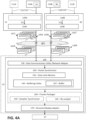
- FIG. 4A is a block diagram depicting the configuration of the synchronization system 100 according to an embodiment of the present invention, and its connection with other modules/utilities of system 10.
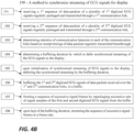
- Fig. 4B is a flow diagram illustrating a method 190 for synchronizing between bio-signals sensed by sensors of several medical devices such as 110A and 110B of system 10 and acquired by respective the PIU 30 and SPU 31 utilities associated therewith.
- the utilities 30 and 31 may be respectively connected to the medical devices 110A and 110B (and optionally to additional medical devices such as 111A and 111B) to receive analog biopotential signals, 121 and 122, or digital biopotential signals 151 and 152, sensed thereby.
- the corresponding utility i.e., utility 31 and/or 30, may include a respective sampling utility 120A or 120B adapted for sampling the respective signals to obtain the digitized form thereof 151 and 152.
- the SPU 31 and PIU 30 utilities also include respective network adapters 124A and 124B configured and operable for establishing respective communication data-links 145A and 145B between the respective utilities associated therewith and the workstation 55 through a data communication network NET, for communicating the respective digital biopotential signals 151 and 152 obtained thereby to the workstation 55.
- the network NET may be for example any suitable data communication network such as LAN or WIFI or any other data communication network suitable implemented for communicating medical signals to the workstation 55 during medical procedures.
- the communication data-links 145A and 145B between the utilities 31 and 30 and the workstation 55 may be established for example based on TCP/IP protocol or like protocols providing reliable (e.g. validated) communication of data packets through the network.
- network adapters 124A and 124B pack the respective bio-signals 151 and 152 obtained by their respective utilities 31 and 30, and send them in respective series of transmitted data packets, 141T and 142T, which are transmitted to workstation 55 through the corresponding data-links 145A and 145B established between the utilities 31 and 30 and the work station 55.
- the bio-signals 151 and 152 are typically sampled at constant rates and are therefore data packets of the series of transmitted data packets 141T and 142T are typically packed and transmitted by the utilities 31 and 30 at substantially regular time intervals ⁇ t 1 and ⁇ t 2 over time t as illustrated in Fig. 4A .
- the synchronization system 100 in this embodiment is adapted to monitor the communication latencies with the different medical hardware (e.g., utilities 31 and 30) that collect the biopotential signals measured by the different medical devices, and accordingly adjusting the display timings of the signals so as to mitigate over these communication latencies, to enable their co-presentation in timely synchronized manner.
- the different medical hardware e.g., utilities 31 and 30
- Synchronization system 100 includes a data communication utility 130 (e.g. network adapter) that is configured and operable to establish the first and second communication data-links 145A and 145B with the respective utilities 31 and 30 and to receive therethrough respective first and second received sequences of data-packets 141R and 142R in response to the sequences 141T and 142T transmitted by utilities 31 and 30.
- a data communication utility 130 e.g. network adapter
- the received first sequence of data-packets 141R includes a plurality of first digitized physiological/biopotential signals 151, which are sampled from sensors of at least one first medical device 110A and packed and transmitted over said first communication link 145A by the first utility 31; and the received second sequence of data-packets 142R includes a plurality of second digitized physiological/biopotential signals 152, which are sampled from sensors of at least one second medical device 110B and packed and transmitted over the second communication link 145B by the second utility 30.
- the first and second sequence of data-packets 141R and 142R are preferably communicated utilizing reliable/validated communication protocol such as TCP in order to ensure their consistent receipt by the work station 55 so that signal portions packed by each data packet can consistently/reliably be displayed on display 27, without loss of signal information due to miscommunication of data packets.
- reliable/validated communication protocol such as TCP
- variable latencies in the communication time intervals between receipt of data packets in each of the first and second received sequence 141R and 142R and possibly the order of their receipt may vary with respect to the time intervals and order of their transmission 141T and 142T. Consequently, if the portions of the signals 151 and 152 provided by respective ones of these data packets were to be presented in the display 27 in actual full-real-time (i.e. as soon as the data packets are received), variable time lags between the presentation of different biopotential signal portions will be introduced in their presentation to the physician which might result with inconsistent and possibly misleading presentation of the biopotential signals to the physician.
- the system 100 may therefore operate in pseudo-real-time with introduction of certain moderate time delay to the presentation not exceeding a certain time-delay threshold (e.g. of up to 150ms) between the sensing of the biopotential signals and their presentation.
- a certain time-delay threshold e.g. of up to 150ms
- Such pseudo-real-time operation facilitates consistent and timely ordered presentation of the biopotential signals 151 and 152 to the physician (mitigating the network latencies), while practically presentation of the biopotential signals to the physician with such moderate delays does not impair the medical procedure as the time lag introduced is on the one hand small enough so as not to be noticeable/meaningful for the medical operation, while on the other hand sufficient for establishing consistent presentation of the biopotential signals on the display 27.
- the system 100 includes a packet synchronizer 140 including a data-links monitor 142 and a buffering utility 145.
- the communication-links monitor 142 is connected to the data communication utility 130 and adapted to monitor receipt timings of data-packet of the data-packet sequences 141R and 142R received through each of the first and second data-links 145A and 145B.
- the communication-links monitor 142 thereby determines the statistics of latencies of communication of data packets through each of the first and second data-links145A and 145B.
- the buffering utility 145 is configured and operable to utilize the statistic of the latencies of the data-links 145A and 145B to determine a buffering duration ⁇ T by which to defer streaming to the display 27, of the biopotential signals that are provided in data-packet of the data-packet sequences 141R and 142R.
- the buffering utility 145 is associated with a data-storage/buffer 147 (such as computer memory e.g., RAM) and is configured and operable for buffering in said buffer 147, portions of the first and second digitized biopotential signals 151 and 152 that are provided in the data-packet sequences 141R and 142R.
- a data-storage/buffer 147 such as computer memory e.g., RAM
- the system 100 further includes a frame-packager 160 configured and operable to successively retrieve in data-packet of the data-packet sequences 141R and 142R from the buffer (e.g. after laps of the buffering duration) and repackage successive sets of samples of the portions of the biopotential signals 151 and 152 retrieved from the buffer 147, according to their sampling order, and utilize them to form a sequence of successive signal-frames which are to be streamed for display by display 27.
- a frame-packager 160 configured and operable to successively retrieve in data-packet of the data-packet sequences 141R and 142R from the buffer (e.g. after laps of the buffering duration) and repackage successive sets of samples of the portions of the biopotential signals 151 and 152 retrieved from the buffer 147, according to their sampling order, and utilize them to form a sequence of successive signal-frames which are to be streamed for display by display 27.
- the system 100 may include, or be associated with, a streamer 170 (e.g., which may for example be implemented by a display adapter or a network streamer) that is adapted to operate upon laps of the buffering duration for streaming said signal-frames to the display 27 at a predetermined/set frame rate.
- a streamer 170 e.g., which may for example be implemented by a display adapter or a network streamer
- biopotential/ECG signals synchronized by the system 100 of this embodiment may be used not necessarily for display, or not only for the display, but optionally also carrying out additional processing.
- the biopotential/ECG signals synchronized by the system 100 may be stored for further analysis and/or used for computation of activation sequences, representing indicia thereof in relation to anatomical maps, and/or other processing as may be required.
- Operations 191 and 192 which may be performed by the data communication utility 130 in parallel, the data communication utility 130 receives the 1 st and 2 nd sequences of data-packets in which generally 1 st and 2 nd digitized biopotential signals or portions thereof are received through the respective datalinks.
- the statistics of the communication latencies in each of the datalinks 145A and 145B is determined in operation 193 by the data-links monitor 142.
- the data-links monitor may be adapted to apply statistical processing to the receipt timings of data-packets from the respective 1 st and 2 nd utilities, 31 and 30, and thereby determine standard-deviations ⁇ A , ⁇ B , or variances of the latencies in transmission of data packets through each the data-links 145A and 145B respectively.
- the data-links monitor 142 may not obtain information about transmission times of the respective data packets and the statistical calculation may be performed under consideration of an operation scheme by which the data packets transmitted through each of the data-links 145A and 145B are transmitted in substantially regular/equal time intervals.
- Such operation scheme in which the data packets are practically transmitted through each data-link 145A or 145B at substantially regular/equal time intervals may be implemented in some embodiments of the present invention where the data packets carrying similar size portions (e.g. of similar durations/numbers-of samples) of the biopotential signals communicated thereby.
- similar size portions e.g. of similar durations/numbers-of samples
- the data-links monitor 142 may utilize information of both the transmission times of the data-packets (which may be indicated in the respective data packets themselves) as well as their receipt timings by the network communication utility 130, in order to determine the latency statistics of the respective data-links 145A and 145B. It will be appreciated a person of ordinary skill in the art will readily appreciate how to determine the latency statistics of the data links in either the above techniques.
- the buffering utility 145 determines a buffering duration ⁇ T by which to defer synchronized streaming to the display of the biopotential signals/portions thereof which are received through the data packets.
- the buffering duration ⁇ T is set to match a predetermined multiple n of a largest standard deviation among the standard deviations ⁇ A , ⁇ B in the latency statistics of the respective datalinks 145A and 145B, while not exceeding a predetermined maximal buffering threshold ⁇ T MAX in order to facilitate pseudo-real-time presentation of the biopotential signals on the display 27.
- the packet synchronizer 140 deferring the synchronized streaming by the buffering duration ⁇ T, and in operation 196 the buffering utility 145 operates to buffer/store the 1 st and 2 nd biopotential signals 151 and 152 received through the data-packets through the 1 st and 2 nd data-links, in the buffer 147.
- the frame-packager 160 operates to generate a sequence of successive signal-frames presenting the portions of the biopotential signals 151 and 152 of which all counterparts were received through the data communication links 145A and 145B (e.g., stored in the buffer 147).
- This may include packaging and formatting successive sets of signal samples of the first and second pluralities of biopotential signals from the buffer according to their sampling order, to form a sequence of successive signal-frames to be displayed on the display 27.
- overlapping sets of signal samples may be packaged in consecutive signal-frames so the display displays a video presenting a continuous /smooth change of the biopotential signals over time.
- the sampling resolution of the sets of signal samples of the biopotential signals is higher than the display/frame resolution of the signal frames presenting the biopotential signals on the display.
- the frame-packager 160 may include a re-sampler 165 configured and operable for resampling the sets of samples of the signals that are to be presented in the signal frames in order reduce their resolution and facilitate their presentation in sad signals frames.
- System 100 and method 190 and of Figs. 4A and 4B thereby provide packet synchronization for synchronizing between data-packets carrying bipotential signals of different medical devices communicated over different data-links of variable latencies and enable synchronized concurrent presentation of the bipotential signals sensed by the different medical devices in pseudo-real-time.
- the system 100 optionally also includes the synchronizer 150 that is described above with reference to Figs. 3A to 3B .
- the synchronizer 150 may be for example operated according to the above-described method 180 for synchronizing between the samples of the sets of signal samples of biopotential signals that are packaged in each signal frame. More specifically the synchronizer processes the sets of signal samples to identify and remove extra samples obtained in one or more of the sets as a result of a difference between sampling rates of the first and second utilities, and thereby mitigates any mis-synchronization between sample sets sampled by non-synchronized sampling utilities of different medical devices.
- the system 100 applies both packet synchronization as well as sample synchronizations to the signals received from the plurality of medical devices.
- biopotential signals such as electrocardiograms (ECG), electrograms (EGM) and intracardiac electrograms (IEGN).
- ECG electrocardiograms
- EMM electrograms
- IEGN intracardiac electrograms
- ECG electrocardiogram
Landscapes
- Health & Medical Sciences (AREA)
- Life Sciences & Earth Sciences (AREA)
- Engineering & Computer Science (AREA)
- Public Health (AREA)
- Medical Informatics (AREA)
- Surgery (AREA)
- General Health & Medical Sciences (AREA)
- Biomedical Technology (AREA)
- Molecular Biology (AREA)
- Veterinary Medicine (AREA)
- Animal Behavior & Ethology (AREA)
- Heart & Thoracic Surgery (AREA)
- Biophysics (AREA)
- Pathology (AREA)
- Physics & Mathematics (AREA)
- Cardiology (AREA)
- Physiology (AREA)
- Epidemiology (AREA)
- Primary Health Care (AREA)
- Nuclear Medicine, Radiotherapy & Molecular Imaging (AREA)
- Otolaryngology (AREA)
- Artificial Intelligence (AREA)
- Computer Vision & Pattern Recognition (AREA)
- Psychiatry (AREA)
- Signal Processing (AREA)
- Physical Education & Sports Medicine (AREA)
- Plasma & Fusion (AREA)
- Databases & Information Systems (AREA)
- Data Mining & Analysis (AREA)
- Computer Networks & Wireless Communication (AREA)
- Measurement And Recording Of Electrical Phenomena And Electrical Characteristics Of The Living Body (AREA)
Applications Claiming Priority (1)
| Application Number | Priority Date | Filing Date | Title |
|---|---|---|---|
| US18/213,313 US20240423555A1 (en) | 2023-06-23 | 2023-06-23 | System and Method of Synchronization of Biopotential Signals |
Publications (2)
| Publication Number | Publication Date |
|---|---|
| EP4491105A2 true EP4491105A2 (fr) | 2025-01-15 |
| EP4491105A3 EP4491105A3 (fr) | 2025-04-23 |
Family
ID=91664159
Family Applications (1)
| Application Number | Title | Priority Date | Filing Date |
|---|---|---|---|
| EP24183586.7A Pending EP4491105A3 (fr) | 2023-06-23 | 2024-06-21 | Système et procédé de synchronisation de signaux biopotentiels |
Country Status (5)
| Country | Link |
|---|---|
| US (1) | US20240423555A1 (fr) |
| EP (1) | EP4491105A3 (fr) |
| JP (1) | JP2025003413A (fr) |
| CN (1) | CN119174611A (fr) |
| IL (1) | IL313775A (fr) |
Citations (14)
| Publication number | Priority date | Publication date | Assignee | Title |
|---|---|---|---|---|
| US5443489A (en) | 1993-07-20 | 1995-08-22 | Biosense, Inc. | Apparatus and method for ablation |
| US5558091A (en) | 1993-10-06 | 1996-09-24 | Biosense, Inc. | Magnetic determination of position and orientation |
| US6172499B1 (en) | 1999-10-29 | 2001-01-09 | Ascension Technology Corporation | Eddy current error-reduced AC magnetic position measurement system |
| US6239724B1 (en) | 1997-12-30 | 2001-05-29 | Remon Medical Technologies, Ltd. | System and method for telemetrically providing intrabody spatial position |
| US6332089B1 (en) | 1996-02-15 | 2001-12-18 | Biosense, Inc. | Medical procedures and apparatus using intrabody probes |
| US6484118B1 (en) | 2000-07-20 | 2002-11-19 | Biosense, Inc. | Electromagnetic position single axis system |
| US6618612B1 (en) | 1996-02-15 | 2003-09-09 | Biosense, Inc. | Independently positionable transducers for location system |
| US6690963B2 (en) | 1995-01-24 | 2004-02-10 | Biosense, Inc. | System for determining the location and orientation of an invasive medical instrument |
| US6892091B1 (en) | 2000-02-18 | 2005-05-10 | Biosense, Inc. | Catheter, method and apparatus for generating an electrical map of a chamber of the heart |
| US7536218B2 (en) | 2005-07-15 | 2009-05-19 | Biosense Webster, Inc. | Hybrid magnetic-based and impedance-based position sensing |
| US7756576B2 (en) | 2005-08-26 | 2010-07-13 | Biosense Webster, Inc. | Position sensing and detection of skin impedance |
| US7848787B2 (en) | 2005-07-08 | 2010-12-07 | Biosense Webster, Inc. | Relative impedance measurement |
| US7869865B2 (en) | 2005-01-07 | 2011-01-11 | Biosense Webster, Inc. | Current-based position sensing |
| US8456182B2 (en) | 2008-09-30 | 2013-06-04 | Biosense Webster, Inc. | Current localization tracker |
Family Cites Families (8)
| Publication number | Priority date | Publication date | Assignee | Title |
|---|---|---|---|---|
| US4958640A (en) * | 1988-12-23 | 1990-09-25 | Spacelabs, Inc. | Method and apparatus for correlating the display of information contained in two information signals |
| US8175076B2 (en) * | 2007-11-20 | 2012-05-08 | Siemens Medical Solutions Usa, Inc. | Medical device synchronization system for use in cardiac and other patient monitoring |
| US9241632B2 (en) * | 2011-07-20 | 2016-01-26 | Biosense Webster (Israel) Ltd. | Synchronization of wireless catheters |
| US20140169162A1 (en) * | 2012-12-17 | 2014-06-19 | St. Jude Medical Ab | Method and system to manage real-time and non-real-time data transmission over a shared link with an imd |
| US20140275888A1 (en) * | 2013-03-15 | 2014-09-18 | Venture Gain LLC | Wearable Wireless Multisensor Health Monitor with Head Photoplethysmograph |
| US10561320B2 (en) * | 2015-12-21 | 2020-02-18 | Zoll Medical Corporation | Time synchronization in a medical device system or network |
| US10686715B2 (en) * | 2018-05-09 | 2020-06-16 | Biosig Technologies, Inc. | Apparatus and methods for removing a large-signal voltage offset from a biomedical signal |
| US11504042B2 (en) * | 2019-06-19 | 2022-11-22 | Biosense Webster (Israel) Ltd. | Extension of electrocardiography (ECG) acquisition capabilities of catheter-based cardiac system |
-
2023
- 2023-06-23 US US18/213,313 patent/US20240423555A1/en active Pending
-
2024
- 2024-06-20 IL IL313775A patent/IL313775A/en unknown
- 2024-06-21 EP EP24183586.7A patent/EP4491105A3/fr active Pending
- 2024-06-21 JP JP2024100319A patent/JP2025003413A/ja active Pending
- 2024-06-21 CN CN202410808532.1A patent/CN119174611A/zh active Pending
Patent Citations (15)
| Publication number | Priority date | Publication date | Assignee | Title |
|---|---|---|---|---|
| US5443489A (en) | 1993-07-20 | 1995-08-22 | Biosense, Inc. | Apparatus and method for ablation |
| US5558091A (en) | 1993-10-06 | 1996-09-24 | Biosense, Inc. | Magnetic determination of position and orientation |
| US6690963B2 (en) | 1995-01-24 | 2004-02-10 | Biosense, Inc. | System for determining the location and orientation of an invasive medical instrument |
| US6618612B1 (en) | 1996-02-15 | 2003-09-09 | Biosense, Inc. | Independently positionable transducers for location system |
| US6332089B1 (en) | 1996-02-15 | 2001-12-18 | Biosense, Inc. | Medical procedures and apparatus using intrabody probes |
| US6788967B2 (en) | 1997-05-14 | 2004-09-07 | Biosense, Inc. | Medical diagnosis, treatment and imaging systems |
| US6239724B1 (en) | 1997-12-30 | 2001-05-29 | Remon Medical Technologies, Ltd. | System and method for telemetrically providing intrabody spatial position |
| US6172499B1 (en) | 1999-10-29 | 2001-01-09 | Ascension Technology Corporation | Eddy current error-reduced AC magnetic position measurement system |
| US6892091B1 (en) | 2000-02-18 | 2005-05-10 | Biosense, Inc. | Catheter, method and apparatus for generating an electrical map of a chamber of the heart |
| US6484118B1 (en) | 2000-07-20 | 2002-11-19 | Biosense, Inc. | Electromagnetic position single axis system |
| US7869865B2 (en) | 2005-01-07 | 2011-01-11 | Biosense Webster, Inc. | Current-based position sensing |
| US7848787B2 (en) | 2005-07-08 | 2010-12-07 | Biosense Webster, Inc. | Relative impedance measurement |
| US7536218B2 (en) | 2005-07-15 | 2009-05-19 | Biosense Webster, Inc. | Hybrid magnetic-based and impedance-based position sensing |
| US7756576B2 (en) | 2005-08-26 | 2010-07-13 | Biosense Webster, Inc. | Position sensing and detection of skin impedance |
| US8456182B2 (en) | 2008-09-30 | 2013-06-04 | Biosense Webster, Inc. | Current localization tracker |
Non-Patent Citations (1)
| Title |
|---|
| XIAO RAN ET AL: "Time Synchronization of Multimodal Physiological Signals through Alignment of Common Signal Types and Its Technical Considerations in Digital Health", JOURNAL OF IMAGING, vol. 8, no. 5, 21 April 2022 (2022-04-21), pages 120, XP093178959, ISSN: 2313-433X, Retrieved from the Internet <URL:https://www.ncbi.nlm.nih.gov/pmc/articles/PMC9145353/pdf/jimaging-08-00120.pdf> DOI: 10.3390/jimaging8050120 * |
Also Published As
| Publication number | Publication date |
|---|---|
| US20240423555A1 (en) | 2024-12-26 |
| EP4491105A3 (fr) | 2025-04-23 |
| CN119174611A (zh) | 2024-12-24 |
| JP2025003413A (ja) | 2025-01-09 |
| IL313775A (en) | 2025-01-01 |
Similar Documents
| Publication | Publication Date | Title |
|---|---|---|
| JP7789485B2 (ja) | 自動パターン取得 | |
| US10856760B2 (en) | Method and system for detection of biological rhythm disorders | |
| EP3395243B1 (fr) | Machine pour la localisation automatique de sources de troubles de rythme biologique | |
| EP2705464B1 (fr) | Système et méthode de ciblage des troubles du rythme cardiaque par ablation selon une forme définie | |
| US12543994B2 (en) | Intracardiac unipolar far field cancelation using multiple electrode cathethers | |
| JP6702712B2 (ja) | 心室遠距離場の低減 | |
| KR20080066616A (ko) | 심장성 부정맥 전도성 경로 및 병소의 확인을 위한자동화된 페이스 맵핑의 컴퓨터 실행방법과 장치 | |
| WO2000045700A1 (fr) | Procedes et systemes de localisation de circuits re-entrants a partir de caracteristiques d'un electrogramme | |
| CN112914586B (zh) | 心内图案匹配 | |
| EP3666181A1 (fr) | Affichage de type d'arythmie | |
| Ihara et al. | Adaptation of the standard 12-lead electrocardiogram system dedicated to the analysis of atrial fibrillation | |
| EP4159127B1 (fr) | Détection automatique du faisceau de his lors d'un mappage électrophysiologique | |
| EP4491105A2 (fr) | Système et procédé de synchronisation de signaux biopotentiels | |
| CN111345813B (zh) | 使用不同时序图案显示来使不同心律可视化 | |
| EP4706524A1 (fr) | Systèmes et procédés de détection de position | |
| EP4523618A1 (fr) | Système de traitement de signaux de localisation | |
| US20250009277A1 (en) | Cardiac diagnostic system | |
| EP4572664A1 (fr) | Systèmes et procédés de navigation électrocardiographique radiale en profondeur de dispositifs intracardiaques |
Legal Events
| Date | Code | Title | Description |
|---|---|---|---|
| PUAI | Public reference made under article 153(3) epc to a published international application that has entered the european phase |
Free format text: ORIGINAL CODE: 0009012 |
|
| STAA | Information on the status of an ep patent application or granted ep patent |
Free format text: STATUS: THE APPLICATION HAS BEEN PUBLISHED |
|
| AK | Designated contracting states |
Kind code of ref document: A2 Designated state(s): AL AT BE BG CH CY CZ DE DK EE ES FI FR GB GR HR HU IE IS IT LI LT LU LV MC ME MK MT NL NO PL PT RO RS SE SI SK SM TR |
|
| PUAL | Search report despatched |
Free format text: ORIGINAL CODE: 0009013 |
|
| AK | Designated contracting states |
Kind code of ref document: A3 Designated state(s): AL AT BE BG CH CY CZ DE DK EE ES FI FR GB GR HR HU IE IS IT LI LT LU LV MC ME MK MT NL NO PL PT RO RS SE SI SK SM TR |
|
| RIC1 | Information provided on ipc code assigned before grant |
Ipc: A61B 5/367 20210101ALI20250320BHEP Ipc: A61B 5/339 20210101ALI20250320BHEP Ipc: A61B 5/33 20210101ALI20250320BHEP Ipc: A61B 5/287 20210101ALI20250320BHEP Ipc: A61B 5/282 20210101ALI20250320BHEP Ipc: A61B 5/00 20060101AFI20250320BHEP |
|
| STAA | Information on the status of an ep patent application or granted ep patent |
Free format text: STATUS: REQUEST FOR EXAMINATION WAS MADE |
|
| 17P | Request for examination filed |
Effective date: 20251001 |
|
| STAA | Information on the status of an ep patent application or granted ep patent |
Free format text: STATUS: EXAMINATION IS IN PROGRESS |
|
| 17Q | First examination report despatched |
Effective date: 20260323 |