EP4491275A1 - Espaceur en forme de cadre pour porte-pointes de pipette - Google Patents
Espaceur en forme de cadre pour porte-pointes de pipette Download PDFInfo
- Publication number
- EP4491275A1 EP4491275A1 EP24169581.6A EP24169581A EP4491275A1 EP 4491275 A1 EP4491275 A1 EP 4491275A1 EP 24169581 A EP24169581 A EP 24169581A EP 4491275 A1 EP4491275 A1 EP 4491275A1
- Authority
- EP
- European Patent Office
- Prior art keywords
- spacer
- pipette tip
- carrier
- protrusions
- side wall
- Prior art date
- Legal status (The legal status is an assumption and is not a legal conclusion. Google has not performed a legal analysis and makes no representation as to the accuracy of the status listed.)
- Pending
Links
Images




Classifications
-
- B—PERFORMING OPERATIONS; TRANSPORTING
- B01—PHYSICAL OR CHEMICAL PROCESSES OR APPARATUS IN GENERAL
- B01L—CHEMICAL OR PHYSICAL LABORATORY APPARATUS FOR GENERAL USE
- B01L9/00—Supporting devices; Holding devices
- B01L9/54—Supports specially adapted for pipettes and burettes
- B01L9/543—Supports specially adapted for pipettes and burettes for disposable pipette tips, e.g. racks or cassettes
-
- B—PERFORMING OPERATIONS; TRANSPORTING
- B65—CONVEYING; PACKING; STORING; HANDLING THIN OR FILAMENTARY MATERIAL
- B65D—CONTAINERS FOR STORAGE OR TRANSPORT OF ARTICLES OR MATERIALS, e.g. BAGS, BARRELS, BOTTLES, BOXES, CANS, CARTONS, CRATES, DRUMS, JARS, TANKS, HOPPERS, FORWARDING CONTAINERS; ACCESSORIES, CLOSURES, OR FITTINGS THEREFOR; PACKAGING ELEMENTS; PACKAGES
- B65D25/00—Details of other kinds or types of rigid or semi-rigid containers
- B65D25/02—Internal fittings
- B65D25/10—Devices to locate articles in containers
- B65D25/108—Devices, e.g. plates, presenting apertures through which the articles project
-
- B—PERFORMING OPERATIONS; TRANSPORTING
- B01—PHYSICAL OR CHEMICAL PROCESSES OR APPARATUS IN GENERAL
- B01L—CHEMICAL OR PHYSICAL LABORATORY APPARATUS FOR GENERAL USE
- B01L2200/00—Solutions for specific problems relating to chemical or physical laboratory apparatus
- B01L2200/02—Adapting objects or devices to another
- B01L2200/025—Align devices or objects to ensure defined positions relative to each other
-
- B—PERFORMING OPERATIONS; TRANSPORTING
- B01—PHYSICAL OR CHEMICAL PROCESSES OR APPARATUS IN GENERAL
- B01L—CHEMICAL OR PHYSICAL LABORATORY APPARATUS FOR GENERAL USE
- B01L2300/00—Additional constructional details
- B01L2300/08—Geometry, shape and general structure
- B01L2300/0809—Geometry, shape and general structure rectangular shaped
Definitions
- the current invention relates to a frame-shaped, essentially rectangular spacer for a rectangular pipette tip carrier, the spacer being configured to be stacked on top of another spacer thereby providing a vertical space between the spacers for the pipette tip carrier.
- An assembly comprising a stack of at least two spacers with the pipette tip carrier positioned between the two spacers and use of a spacer to create an alternating stack of spacers and pipette tip carriers.
- liquid handling platforms are frequently used for this purpose, which enable the aspirating and/or dispensing of liquid volumes with high precision and, nonetheless, high throughput rates for the liquids and samples.
- Such liquid handling platforms very often comprise pipetting robots, which are equipped with disposable or single-use pipette tips to avoid contamination between processing or sample liquids.
- Liquid handling platforms are typically charged with such disposable pipette tips, in that carrier plates or carrier trays equipped with pipette tips or even stacks of such carrier plates are provided.
- Such carrier plates typically comprise an array of pipette tips arranged in a standardized matrix so that a pipetting head of a pipetting robot can collect one or more of these pipette tips from a known position.
- Multichannel pipetting heads of the pipetting robot can collect one or more rows of pipettes or an array of pipettes from the carrier plate by coupling each of the pipetting heads to the pipettes in the carrier.
- the pipetting head pushes onto the pipette tips and thereby applies a vertical load onto the pipette carrier for elastically deforming a collar of the pipette tip or elastically deforming a rubber seal on the pipetting head.
- a friction fit engagement between the pipetting head and the collar of the pipette facilitates the pick-up of the pipette.
- the pipettes used by the robot for aspirating and dispensing liquids are disposed after use leading to an increased demand for disposable pipette tips which need to be stored within the pipetting robot.
- Space saving solutions have been developed for the storage of the disposable tips, for example by stacking multiple pipette tip carriers using spacers.
- EP2210668A2 discloses a storage system which comprises a frame-shaped as a rectangular box and a rectangular pipette carrier plate having a plurality of holes arranged in a matrix for the insertion of pipette tips.
- the pipette carrier plate can be placed on top of the rectangular box such that the space in the box is available for the pipette tips extending through the holes of the carrier plate.
- Spacers are disclosed for providing an alternating stack including multiple pipette carrier plates each separated by a spacer.
- the spacer includes a rectangular frame surrounding a plate with passages arranged according to the same pattern as the holes in the pipette carrier plate, such that pipette tips inserted into a carrier are guided through the passages of the spacer.
- the end of the pipetting tips engaging the carrier fit into the openings of pipettes disposed on a subjacent carrier separated by the spacer.
- EP2848308B1 discloses a rectangular spacer for stacking rectangular pipette tip carriers on top of each other.
- the spacers are sandwiched between two carriers and vertical loads, for example during pick-up of the pipettes by the robot, are transferred in an alternating way from a carrier to a spacer.
- Each spacer includes two elastic elements in the vicinity of each corner which may be flexed by guiding surfaces of a subjacent pipette carrier when the spacer is placed onto the subjacent carrier.
- the elastic elements intend to reduce the horizontal play within a stack of multiple carriers and spacers.
- the vertical load during pick-up of the pipettes is transferred from the edges of the carrier to the spacers requiring a stiff construction of the carriers and the spacers.
- a further objective is to provide assemblies of pipette carriers and spacers with an effective spacer-to-spacer load transfer which require less material or reduce the carbon footprint for the assembly.
- a first aspect relates to a frame-shaped essentially rectangular spacer for a rectangular pipette tip carrier, the spacer being configured to be stacked on top of another spacer thereby providing a vertical space between the spacers for the pipette tip carrier.
- the spacer may be stacked on top of a pipette box intended to be placed on a working table of the pipetting robot.
- the spacer includes a horizontal base surface connected to a peripheral side wall which stands essentially perpendicular to the base surface providing two longitudinal sides and two transverse sides. Each longitudinal side and each transverse side include an inner side or inner surface connected to the base surface.
- the peripheral side wall includes an upper surface arranged on an upper rim of the peripheral side wall and a lower surface arranged on a lower rim of the peripheral side wall.
- the upper and lower surfaces or rims extend essentially horizontally and are preferably arranged parallel to another.
- the upper surface of the peripheral side wall or at least a part of the upper rim is configured to support the pipette tip carrier.
- the spacer includes load transfer elements which are configured to transfer a vertical load directly from one spacer to a subjacent spacer. The vertical load may be applied to a pipette tip carrier positioned on the upper rim of the top spacer.
- the vertical load in a stack of alternating spacers and pipette tip carriers is subsequently transferred from spacer-to spacer without transferring the vertical load to one of the pipette tip carriers positioned between the spacers.
- Transferring the load from spacer-to-spacer via the load transfer elements without vertical forces transmitted to the pipette tip carriers implies that the stack-up of dimensional tolerances in a stack of multiple spacers and carriers is dominated by the manufacturing tolerances for the spacer as the pipette tip carrier is not vertically loaded.
- the manufacturing tolerances for the spacer therefore need to be tighter, or in other words, the dimensional precision for the pipette tip carrier may be less demanding compared to a stack of alternating spacers and carriers with a spacer-to-carrier loading.
- the mechanical strength of the pipette carrier may also be adjusted to the spacer-to-spacer loading principle such that wall thicknesses may be reduced leading to less use of for example polymeric material, thereby reducing the carbon footprint for the carrier and therewith the carbon footprint for a stack of carriers and spacers.
- the load transfer elements on each spacer may include protrusions that vertically extend from the upper surface of the spacer, for example from each corner of the spacer.
- the spacer may include at least one protrusion vertically extending from the top surface, preferably include two protrusions, more preferably three protrusions and most preferably four protrusions.
- the protrusions may be located in the vicinity of the corners of the rectangular spacer or located at each corner.
- the protrusions may be oriented perpendicular to the horizontal base surface or may be angulated with respect to the horizontal base surface.
- the protrusions may be all oriented parallel to another or one or more of the protrusions is positioned at a different angle with respect to the horizontal base surface compared to the other protrusions.
- Each protrusion may have a hemi-spherical end surface, a sloped end surface, a cone shaped end surface or a surface that is essentially parallel to the horizontal base surface.
- Each protrusion may include a facet surrounding the end surface.
- the cross section for the protrusions may be circular for cylindrical protrusions or may be a rectangle, a triangle or an ellipse.
- the end surface of the protrusion is adapted to engage a stop surface on a superjacent spacer.
- the stop surfaces may be recessed from the lower surface or lower rim of the spacer and may be positioned on one or on each corner of the spacer or may be positioned in the vicinity of one or each corner of the spacer.
- the stop surfaces may be complementary to the end surface of the protrusions of a subjacent spacer and may be flat, sloped or hemispherical.
- the stop surfaces on each corner and the end surfaces on each protrusion of a spacer define a virtual plane and the plane connecting the end surfaces on the protrusions and the plane connecting the stop surfaces are preferably oriented parallel to another and preferably oriented parallel to the horizontal base surface.
- the vertical distance between the upper rim and lower rim of the peripheral side wall is preferably below the length of the load transfer element defined by the vertical distance between the end of the protrusion vertically extending from the upper surface and the stop surface recessed from the lower surface.
- a vertical gap will be available for a pipette tip carrier when stacked between two spacers preventing vertical loading from one spacer to a subjacent spacer via the pipette tip carrier provided that the vertical dimension of the pipette tip carrier at the location of the peripheral side wall is below the vertical dimension of the gap.
- the horizontal base surface of a spacer may include a projection located at the center of the rectangular spacer which protrudes vertically towards the upper rim of the peripheral side wall and protrudes towards the lower rim of the peripheral side wall and the top surface of the projection is configured to abut a pipette tip carrier positioned on top of the spacer and the bottom surface of the projection is configured to abut a pipette tip carrier positioned below the spacer during vertical loading.
- the projection is preferably coupled to the horizontal base surface and integrally formed with the rectangular spacer during, for example, injection molding.
- the projection may project vertically upwards and downwards from the horizontal base surface.
- the projection is a separate part and one part of the projection is snap fitted onto the center of the top surface of the base surface and the other part of the projection is snap fitted onto the center of the bottom surface of the base surface.
- the projections in the center are located on the pipette tip carrier trays which are configured to engage openings in the center of the spacer.
- the projections protruding from the top of the carrier may abut or engage a protrusion protruding from the bottom of a superjacent carrier whereas the projections protruding from the bottom of the carrier may engage a projection protruding from the top surface of a carrier.
- the top and bottom engagements of the center projections pass through the center openings of the spacers placed between carriers.
- the horizontal base may further include ribs projecting from the top surface and/or the bottom surface of the horizontal base for mechanically strengthening the horizontal base surface of the spacer.
- the ribs may be placed between the plurality of openings and may be connected to the center projection discussed above.
- corrugated structures are included in the horizontal base surface or base layer.
- the spacer may include centering spring elements at each corner and the centering spring elements are configured to act upon the protrusions on each corner of a subjacent spacer on which the spacer is positioned with horizontal and/or vertical play thereby acting as a centering aid or as a twist barrier in a stack of the spacer and the subjacent spacer.
- the centering aid correct for the shifts in the horizontal plane.
- the twist barrier realigns a stack of spacers that has been twisted or torqued around the vertical axis of the stack.
- the spring elements of a spacer act directly on a subjacent spacer and are not acting on the pipette tip carrier positioned between the spacer and the subjacent spacer.
- the centering aid provided by the spring elements or the twist barrier act from spacer-to-spacer without involving the pipette tip carrier such that the dimensional manufacturing tolerances for the carriers may be less tight.
- the spring elements are preferably located opposite to the protrusions vertically extending from the top surface and face towards the lower rim.
- the spring elements may be configured to at least partially surround the protrusions on each corner of a subjacent placed spacer.
- the spring elements may extend vertically wherein one end of the spring element is attached or attachable to the bottom of the horizontal base surface and the other end is configured to flex along the diagonal of the rectangular spacer or towards the center of the spacer.
- the spring element may be further mechanically supported by a fin extending from the bottom of the horizontal base surface and which may be coupled or adjacent to the spring element to reduce or adjust the degree of flexing of the spring element.
- a second aspect relates to an assembly comprising a stack of at least two spacers and a rectangular pipette tip carrier positioned between the two spacers wherein the pipette tip carrier comprises a plate comprising:
- the lower surface of the plate or at least the lower surface in a rim section of the plate may engage the upper surface of the subjacent spacer or may engage the ledges protruding from the upper surface of the subjacent spacer.
- the openings in the plate or preferably in a rim section of the plate may be closed opening or may be provided as cut-outs in the rim of the plate.
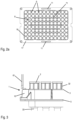
- Hollow cylinders 6 depend from, or start at the circular openings 7 providing a matrix of passages 8 through the pipette tip carrier 1.
- the pipette tip carrier may releasably hold disposable pipette tips 2 using the passages 8 (see Figure 3 ).
- the peripheral wall 4 may include a labelling section 58 for printing information such as the brand name or a two- or three-dimensional barcodes for identification or logistic purposes.
- the peripheral wall 4 may further include indentions 59.
- the rectangular skirt 5 includes a longitudinal side 12 and a transverse side 13 and is relative thin for a material saving product. The thickness of the skirt is below 3 mm, preferably below 2 mm, more preferably below 1.5 mm.
- the relatively thin rectangular skirt 5 is strengthened by a plurality of rim ribs 10 connecting the top surface of the rectangular skirt 5 to the peripheral wall 4.
- the rim ribs 10 furthermore provide guidance to and limit the horizontal play for a lid that may be placed on top of the pipette tip carrier 1.
- the top surface of the rim ribs 10 may be used for mechanically detecting the presence of the pipette tip carrier by a gripper of a pipetting robot.
- the space between two rim ribs 10 on the peripheral wall or on the top surface of the skirt 5 may provide for the labelling section 58.
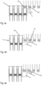
- Figure 4d presents a pipette tip carrier 1 with a missing first row of pipettes 2 and the firmware of the pipetting robot can detect the missing row as the vertical position of the pipetting head 62 with the collar adapters 70 would normally detect an increase in vertical force required for the pick-up of the pipettes as the collar adapters 70 may need to elastically deform the rim of the pipette collar 32.
- the collar adapter that is adjacent to the collar adapter entering the passage 8 of the pipette carrier 1 does not abut the thin-walled rectangular skirt 5.
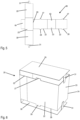
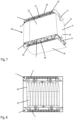
- FIG. 5 to 8 An example for a packaging 20 for the pipette tip carriers is presented in Figures 5 to 8 .
- the packaging 20 is based on a foldable sheet 66 that is punched from a plate of a material such as cardboard, coated cardboard, plastic or a composite material.
- the foldable sheet 66 includes two longitudinal sides 22 connected by a transverse side 23.
- the longitudinal sides 22 each include two protrusions or flaps, a flap or protrusion 27 and a flap or protrusion 28 which, after the sheet 66 has been folded into a rectangular shaped box 24, extend from a top rim 25 and a bottom rim 26 of the packaging 20 (see Figure 6 ).
- a top cover 29 and a bottom cover 30 is attached to one of the two transverse sides 23 and closure lids or closure flaps extend from the top cover and bottom cover respectively.
- Closure slits 63 are included in the other one of the two transverse sides 23 configured for engaging the closure lids 31.
- a closure flap 64 is attached to one of the transverse sides 23 for closing the rectangular box 24.
- Fold lines or predetermined folds are integrated in the foldable sheet 66, for example perforation lines or cutting lines 65 may be integrated in the foldable sheet 66.
- the two protrusions or flaps 27 or 28 may include barbed hooks for releasably fixating the pipette tip carrier to the packaging.
- the sheet 66 may be folded in a rectangular shaped box 24 as presented in Figure 6 providing the folded packaging 20.
- a top rim 25 and bottom rim 26 extend from the upper surface and lower surface of the longitudinal sides 22 and transverse sides 23 thereby providing a top opening and bottom opening that is accessible for insertion of two pipette tip carriers 1.
- the top and bottom openings are surrounded by the top rim and bottom rim, respectively.
- the protrusions or flaps 27, 28 extend from the top rim 25 and bottom rim 26, respectively.
- the top cover 29 and bottom cover 30 can be bent from a vertical orientation allowing access for the carriers towards the top and bottom rim for closing the packaging.
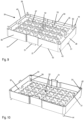
- Load transfer elements 43 are located on each corner of the rectangular shaped spacer 34 which include the protrusion 44 and stop surfaces 45. Optionally, there are additional load transfer elements located between the corners of the spacer. Further details for the load transfer elements will be explained in Figures 14 and 15 .
- the perspective bottom view in Figure 10 further presents spring elements 54 that surround the stop surfaces 45 in each corner and the spring elements 54 are connected to the bottom surface of the horizontal base surface 35 and the free end of the spring element 54 may flex towards the center or towards the corner of the rectangular shaped spacer 34.
- the spring element 54 may be mechanically supported by a support rib 56 that protrudes from the bottom surface of the base 35.
- the load transfer elements 43 provide for the transfer of a vertical load from a spacer to a subjacent spacer whereas the spring elements 54 provide for a correct spacer-to-spacer alignment in a stack of spacers.
- the protrusions 51 protruding downwards from the lower rim of each spacer abut the upper surface 39 of a subjacent spacer either via the cut-outs 55 or via the openings 11 in the rectangular skirt 5 of each pipette tip carrier 1.
- the pipette tip carriers 1 are within a vertical space or gap between two spacers 34 and the vertical load applied to the pipette tip carrier 1 on top of the pile is transferred via the rectangular skirt 5 to the upper rim 40 of the first spacer 34 and the vertical load is subsequently transferred to the second spacer 34 via the load transfer elements 43 on each corner of the first spacer and/or via the protrusions 51 extending from the lower rim of the first spacer.
- the vertical load is finally transmitted to the worktable of the pipetting robot via the pipetting box 68. Details for the load transfer via the load transfer elements 43 are presented in Figure 14 and details for the load transfer via the protrusions 51 are presented in Figure 15 .
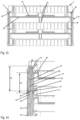
- a longitudinal section for the stack is depicted in Figure 13 .
- the vertical load from the pipette tip carrier 1 on the top is transmitted via the rectangular skirt 5 to the upper rim 40 of the first spacer 34.
- the first spacer 34 includes the base surface 35 surrounded by the peripheral side wall 36 and the base surface 35 is strengthened by the corrugated structures 67 (see also Figure 9 ).
- the projections 52 which do not contact the subjacent or superjacent pipette tip carriers in a resting position, may additionally absorb the vertical loads thereby transferring a minor part of the load in the center from the pipette tip carrier on the top to the first spacer and, eventually, from the first spacer to the next pipette tip carrier.
- Each pipette tip carrier may be placed on the upper rim 40 of a first spacer 34 and a second spacer may be placed on top of the first spacer, and the lower rim 42 of the second spacer will not contact the rectangular skirt 5 surrounding the pipette tip carrier.
- the vertical loads applied to a pipette tip carrier may thus be transferred in a stack of spacers and carriers via the load transfer elements 43 on each corner, and/or via the protrusions 51 on the longitudinal sides of the spacer, and/or via the protrusions 51 on the transverse sides of the spacer for a direct spacer-to-spacer load transfer.
- a part of the vertical load is transmitted via the central projections 52 for spacer-to-carrier loading.
- the spacer 34 includes spring elements 54 on each corner as presented in Figures 10 , Figure 15 and Figure 16 .
- the placement may be accompanied by a shift in the horizontal plane of the one spacer versus the another spacer.
- the play in the horizontal plane is compensated for or eliminated using the spring elements 54 located on each corner.
- the spring element 54 protrudes from the bottom surface of the horizontal base 35 towards the lower rim 42 and can flex along the diagonal of the rectangular shaped spacer towards the center or towards the corner of the peripheral wall 36.
- the spring element 54 of a spacer may have a semi-circular shape for at least partially surrounding the protrusion 44 protruding upwards from of a subjacent spacer.
- the spring elements of the top spacer on each corner can flex when engaging the protrusions 44 of a subj acent spacer and thereby self-center the spacer with respect to the subjacent spacer and compensate for horizontal misplacement or provide a barrier against twisting the stack of spacers.
- the twist barrier provides a resilient realignment force when torquing the top of the stack with respect to the bottom of the stack. Reliable pick-up of the pipettes from the carriers depends on the accuracy for the movements of the pipetting robot and on the dimensional tolerances for a stack of the spacers and the pipette tip carriers.
- the self-centering spring elements may thus reduce the stack-up of tolerances induced by the placements and handling of the spacers and carrier.
- the flexibility or resilience of the spring element may be tuned by the material used for the spring element 54 and/or the wall thickness of the spring elements and/or the use of a support rib 56 protruding along the back surface of the spring element 54 towards the end of the spring element.
- the spring element 54 may surround the stop surface 45 on each corner thereby acting as a guiding element guiding the post 44 of a subjacent spacer towards the stop surface of the spacer on top during spacer placement, see Figure 16 .
- Figure 15 furthermore presents the gap 57 between the two spacers 34 that is available for the pipette tip carrier 1 placed between the two spacers.
- the height of the gap 57 is defined by the difference between the length of the transfer element 49 and the vertical distance 48 between the upper and lower rim of the spacer as presented in Figure 14.
- Figure 14 furthermore presents the spring elements 54 in the longitudinal sectional view engaging the protrusion 44 of a subjacent spacer.
- the spring elements 54 for guiding and aligning the spacers act during pile-up or stacking of the spacers and pipette tip carriers onto each other, this operational step in the laboratory automation procedure is done before starting the liquid handling procedure with the pick-up, and therewith vertical loading of the stacks.
- the spacer presented above in combination with the trays therefore allows for a separation of the correct alignment during stacking and an effective transfer of the vertical loads during liquid handling and this in combination with spacers and pipette tip carriers that require less material during manufacturing and have a lower carbon footprint.
Landscapes
- Health & Medical Sciences (AREA)
- Clinical Laboratory Science (AREA)
- Chemical & Material Sciences (AREA)
- Chemical Kinetics & Catalysis (AREA)
- Engineering & Computer Science (AREA)
- Mechanical Engineering (AREA)
- Devices For Use In Laboratory Experiments (AREA)
- Details Of Rigid Or Semi-Rigid Containers (AREA)
Priority Applications (5)
| Application Number | Priority Date | Filing Date | Title |
|---|---|---|---|
| EP24169581.6A EP4491275A1 (fr) | 2024-04-11 | 2024-04-11 | Espaceur en forme de cadre pour porte-pointes de pipette |
| CN202520056546.2U CN224025072U (zh) | 2024-04-11 | 2025-01-10 | 间隔器和组件 |
| CH000106/2025A CH721593A2 (de) | 2024-04-11 | 2025-02-06 | Ein rahmenförmiger Abstandshalter für Pipettenspitzenträger |
| US19/083,199 US20250319469A1 (en) | 2024-04-11 | 2025-03-18 | Frame-shaped spacer for pipette tip carriers |
| CN202510632766.XA CN120815587A (zh) | 2024-04-11 | 2025-05-16 | 一种隔件、其用途和一种组件 |
Applications Claiming Priority (1)
| Application Number | Priority Date | Filing Date | Title |
|---|---|---|---|
| EP24169581.6A EP4491275A1 (fr) | 2024-04-11 | 2024-04-11 | Espaceur en forme de cadre pour porte-pointes de pipette |
Publications (1)
| Publication Number | Publication Date |
|---|---|
| EP4491275A1 true EP4491275A1 (fr) | 2025-01-15 |
Family
ID=90721041
Family Applications (1)
| Application Number | Title | Priority Date | Filing Date |
|---|---|---|---|
| EP24169581.6A Pending EP4491275A1 (fr) | 2024-04-11 | 2024-04-11 | Espaceur en forme de cadre pour porte-pointes de pipette |
Country Status (4)
| Country | Link |
|---|---|
| US (1) | US20250319469A1 (fr) |
| EP (1) | EP4491275A1 (fr) |
| CN (2) | CN224025072U (fr) |
| CH (1) | CH721593A2 (fr) |
Citations (5)
| Publication number | Priority date | Publication date | Assignee | Title |
|---|---|---|---|---|
| EP2210668A2 (fr) | 2009-01-23 | 2010-07-28 | Eppendorf Ag | Support pour pointes de pipettes |
| EP2839880A1 (fr) * | 2013-08-20 | 2015-02-25 | Eppendorf Ag | Support pour embouts de pipette |
| EP2848308B1 (fr) | 2013-12-20 | 2018-09-05 | Tecan Trading AG | Écarteur pour support pour pointes de pipettes empilées les unes sur les autres |
| EP4190452A1 (fr) | 2021-12-01 | 2023-06-07 | Eppendorf SE | Espaceur permettant de maintenir les porte-pipettes empilés à distance les uns des autres |
| EP4368291A1 (fr) * | 2022-11-08 | 2024-05-15 | TECAN Trading AG | Dispositif de stockage, ensembles correspondants et procédé d'utilisation |
-
2024
- 2024-04-11 EP EP24169581.6A patent/EP4491275A1/fr active Pending
-
2025
- 2025-01-10 CN CN202520056546.2U patent/CN224025072U/zh active Active
- 2025-02-06 CH CH000106/2025A patent/CH721593A2/de unknown
- 2025-03-18 US US19/083,199 patent/US20250319469A1/en active Pending
- 2025-05-16 CN CN202510632766.XA patent/CN120815587A/zh active Pending
Patent Citations (5)
| Publication number | Priority date | Publication date | Assignee | Title |
|---|---|---|---|---|
| EP2210668A2 (fr) | 2009-01-23 | 2010-07-28 | Eppendorf Ag | Support pour pointes de pipettes |
| EP2839880A1 (fr) * | 2013-08-20 | 2015-02-25 | Eppendorf Ag | Support pour embouts de pipette |
| EP2848308B1 (fr) | 2013-12-20 | 2018-09-05 | Tecan Trading AG | Écarteur pour support pour pointes de pipettes empilées les unes sur les autres |
| EP4190452A1 (fr) | 2021-12-01 | 2023-06-07 | Eppendorf SE | Espaceur permettant de maintenir les porte-pipettes empilés à distance les uns des autres |
| EP4368291A1 (fr) * | 2022-11-08 | 2024-05-15 | TECAN Trading AG | Dispositif de stockage, ensembles correspondants et procédé d'utilisation |
Also Published As
| Publication number | Publication date |
|---|---|
| US20250319469A1 (en) | 2025-10-16 |
| CN120815587A (zh) | 2025-10-21 |
| CN224025072U (zh) | 2026-03-24 |
| CH721593A2 (de) | 2025-08-29 |
Similar Documents
| Publication | Publication Date | Title |
|---|---|---|
| US7169361B2 (en) | Pipette tip reloading system | |
| CN106970236B (zh) | 样品试管架和样品试管分析系统 | |
| EP1883475B1 (fr) | Support de tubes de prelevement | |
| US20080240999A1 (en) | Pipette tip transfer system | |
| US9662654B2 (en) | Spacer for pipette tip carriers stacked one on top of another | |
| US5827745A (en) | Micropipette tip loading and unloading device and method and tip package | |
| CN110180606B (zh) | 用于执行自动试剂分析的系统、方法和设备 | |
| CA2264366A1 (fr) | Plateau de rangement pour eprouvettes | |
| EP3639040B1 (fr) | Dispositif et procédé pour la manutention de tubes de test | |
| US7666362B2 (en) | Micro-plate and lid for robotic handling | |
| US20250319470A1 (en) | A packaging for holding two rectangular shaped pipette tip carriers | |
| US20250025881A1 (en) | Spacer for holding pipette tip carriers, which are stacked one over the other, spaced apart | |
| CN107923820B (zh) | 样品收集装置 | |
| US8940248B2 (en) | Kit | |
| EP4491275A1 (fr) | Espaceur en forme de cadre pour porte-pointes de pipette | |
| EP4491276A1 (fr) | Porte-pointes de pipette de forme rectangulaire pour contenir une pluralité de pointes de pipette | |
| EP3678783B1 (fr) | Cadre pour maintenir des ensembles de filtration et unité de test pour test microbiologique | |
| EP4311562A1 (fr) | Dispositif de support pour supporter une pluralité de récipients à usage pharmaceutique à manipuler dans une ligne de traitement | |
| EP4311563A1 (fr) | Dispositif de support pour supporter une pluralité de récipients à usage pharmaceutique à manipuler dans une ligne de traitement | |
| EP4218852B1 (fr) | Dispositif et système de transport de dispositifs médicaux | |
| EP3591407B1 (fr) | Râtelier porte-éprouvettes et ensemble de râtelier porte-éprouvettes | |
| CN220084875U (zh) | 耗材堆叠装置和具有其的样本处理装置 | |
| WO2025024313A1 (fr) | Dispositif de cloisonnement amovible pour maintenir des tubes dans des portoirs d'échantillons | |
| US20170120244A1 (en) | Modular Well Plates | |
| WO2024189337A1 (fr) | Ensemble porte-flacons |
Legal Events
| Date | Code | Title | Description |
|---|---|---|---|
| PUAI | Public reference made under article 153(3) epc to a published international application that has entered the european phase |
Free format text: ORIGINAL CODE: 0009012 |
|
| STAA | Information on the status of an ep patent application or granted ep patent |
Free format text: STATUS: THE APPLICATION HAS BEEN PUBLISHED |
|
| AK | Designated contracting states |
Kind code of ref document: A1 Designated state(s): AL AT BE BG CH CY CZ DE DK EE ES FI FR GB GR HR HU IE IS IT LI LT LU LV MC ME MK MT NL NO PL PT RO RS SE SI SK SM TR |
|
| STAA | Information on the status of an ep patent application or granted ep patent |
Free format text: STATUS: REQUEST FOR EXAMINATION WAS MADE |
|
| 17P | Request for examination filed |
Effective date: 20250508 |