EP4190452A1 - Espaceur permettant de maintenir les porte-pipettes empilés à distance les uns des autres - Google Patents
Espaceur permettant de maintenir les porte-pipettes empilés à distance les uns des autres Download PDFInfo
- Publication number
- EP4190452A1 EP4190452A1 EP21211549.7A EP21211549A EP4190452A1 EP 4190452 A1 EP4190452 A1 EP 4190452A1 EP 21211549 A EP21211549 A EP 21211549A EP 4190452 A1 EP4190452 A1 EP 4190452A1
- Authority
- EP
- European Patent Office
- Prior art keywords
- spacer
- pipette tip
- corners
- side wall
- tip carrier
- Prior art date
- Legal status (The legal status is an assumption and is not a legal conclusion. Google has not performed a legal analysis and makes no representation as to the accuracy of the status listed.)
- Granted
Links
Images







Classifications
-
- B—PERFORMING OPERATIONS; TRANSPORTING
- B01—PHYSICAL OR CHEMICAL PROCESSES OR APPARATUS IN GENERAL
- B01L—CHEMICAL OR PHYSICAL LABORATORY APPARATUS FOR GENERAL USE
- B01L9/00—Supporting devices; Holding devices
- B01L9/54—Supports specially adapted for pipettes and burettes
- B01L9/543—Supports specially adapted for pipettes and burettes for disposable pipette tips, e.g. racks or cassettes
-
- B—PERFORMING OPERATIONS; TRANSPORTING
- B01—PHYSICAL OR CHEMICAL PROCESSES OR APPARATUS IN GENERAL
- B01L—CHEMICAL OR PHYSICAL LABORATORY APPARATUS FOR GENERAL USE
- B01L9/00—Supporting devices; Holding devices
- B01L9/52—Supports specially adapted for flat sample carriers, e.g. for plates, slides, chips
- B01L9/527—Supports specially adapted for flat sample carriers, e.g. for plates, slides, chips for microfluidic devices, e.g. used for lab-on-a-chip
-
- B—PERFORMING OPERATIONS; TRANSPORTING
- B01—PHYSICAL OR CHEMICAL PROCESSES OR APPARATUS IN GENERAL
- B01L—CHEMICAL OR PHYSICAL LABORATORY APPARATUS FOR GENERAL USE
- B01L2200/00—Solutions for specific problems relating to chemical or physical laboratory apparatus
- B01L2200/02—Adapting objects or devices to another
- B01L2200/025—Align devices or objects to ensure defined positions relative to each other
-
- B—PERFORMING OPERATIONS; TRANSPORTING
- B01—PHYSICAL OR CHEMICAL PROCESSES OR APPARATUS IN GENERAL
- B01L—CHEMICAL OR PHYSICAL LABORATORY APPARATUS FOR GENERAL USE
- B01L2300/00—Additional constructional details
- B01L2300/12—Specific details about materials
- B01L2300/123—Flexible; Elastomeric
-
- B—PERFORMING OPERATIONS; TRANSPORTING
- B01—PHYSICAL OR CHEMICAL PROCESSES OR APPARATUS IN GENERAL
- B01L—CHEMICAL OR PHYSICAL LABORATORY APPARATUS FOR GENERAL USE
- B01L3/00—Containers or dishes for laboratory use, e.g. laboratory glassware; Droppers
- B01L3/02—Burettes; Pipettes
- B01L3/0275—Interchangeable or disposable dispensing tips
Definitions
- the invention relates to a spacer for holding stacked plate-shaped and essentially rectangular pipette tip carriers with holes and pipette tips inserted therein at a distance from one another.
- Pipette tips are used in particular in biological, chemical, biochemical, medical or forensic laboratories in order to dispense small amounts of liquid using pipetting devices.
- the pipetting devices are manual pipettes, automatic dosing stations or laboratory machines (workstations).
- the pipetting devices have one or more channels to accommodate a single pipette tip or a plurality of pipette tips in a row or in a matrix arrangement.
- the pipetting devices have projections or blind bores onto or into which the upper ends of the pipette tips can be clamped or clamped.
- the distances between the channels are usually based on the distances between the wells of standardized microplates according to the ANSI SBS 1 to 4 standard; American National Standard; American National Standard Institute, voted 2006.
- the disposable plastic pipette tips are used. These must be made available in large quantities to carry out investigations.
- Plate-shaped and essentially rectangular pipette tip carriers with a large number of holes in a matrix arrangement are used to provide pipette tips.
- the pipette tips are inserted into the holes from above, whereby they do not fall through due to a diameter that widens upwards or a collar.
- the pipette tip carrier is placed on the edge of a top opening of a frame or box so that the Pipette tips engage in the top opening.
- one or more pipette tips can be removed from the pipette tip carrier by pressing onto the attachments or pressing into the blind holes. After use, the pipette tips are released from the pipetting device into a container by means of an ejection device in order to be disposed of.
- the pipette tip carrier with a peripheral side wall that protrudes downward and is supported outside the holes on a pipette tip carrier arranged underneath (cf. EP 2 784 076 A1 ). It is also known to arrange a frame-shaped spacer between stacked pipette tip carriers, which is supported with its upper edge outside the holes on the underside of a pipette tip carrier arranged higher and with its lower edge outside the holes on the upper side of a pipette tip carrier arranged below. In addition, it is known to connect the spacer to the upper pipette tip carrier by means of snap connections (cf. EP 2 839 880 A1 ).
- the EP 2 848 308 B1 describes a spacer comprising centering spring elements arranged on the inside of the longitudinal and transverse sides of the side wall, each comprising a resilient part spaced from the inside of the side wall to which the centering spring element is fixed.
- the resilient part can exert a spring effect between the inside of the respective side wall and a part of a pipette tip carrier to be stacked, which part is received in a central opening of the spacer.
- the centering spring elements are designed in such a way that they act on a pipette tip carrier on which the spacer rests and minimize the horizontal play between the pipette tip carrier and the spacer without locking the pipette tip carrier with the spacer.
- centering spring elements arranged on the inside of the longitudinal and transverse sides of the side wall. In the exemplary embodiment, there are two centering spring elements on each longitudinal and transverse side, ie a total of eight.
- the object of the invention is to provide a spacer for plate-shaped pipette tip carriers stacked on top of one another, which enables improved centering and stabilization of a carrier stack with reduced use of materials and production costs.
- the spacer according to the invention for holding plate-shaped and essentially rectangular pipette tip carriers stacked on top of one another at a distance from one another comprises a peripheral side wall which forms an essentially rectangular frame with two longitudinal and two transverse sides, which has a horizontal standing surface on a lower edge for support on a top side of a pipette tip carrier, on an upper edge a horizontal support surface for supporting a further pipette tip carrier on the underside, on corners between adjacent longitudinal and transverse sides from the upper edge vertically upwards protruding pins and on the side wall bending elements, wherein the bending elements in an acute angle to the adjacent longitudinal and transverse sides extending direction are bendable.
- centering of the spacer in the stack is achieved by the bending elements at the corners of the side wall, which can be bent in a direction running at an acute angle to the adjacent longitudinal and transverse sides.
- the bending elements can be bent or deflected by contours of a further spacer introduced from below into the circumferential side wall and/or a pipette tip carrier supported on the support surface of the introduced further spacer, or rest against them without play.
- the bending of the bending element can be outwards or inwards with respect to the frame of the spacer.
- a slight bending or deflection or play-free contact of the bending elements results in the spacer being centered on the contours of the further spacer introduced from below and/or of a pipette tip carrier supported on the further spacer.
- the forces acting due to the centering between the bending elements and the contours of the spacer or pipette tip carrier can be kept so low that the spacer from the further spacer and the supported thereon pipette tip carrier can be deducted without the further spacer or the pipette tip carrier is taken here.
- This can be achieved in particular by designing the bending elements to be particularly flexible and/or by manufacturing the bending elements and the contours of the spacer and/or the pipette tip carrier precisely or with low tolerances.
- the spacer can be produced in a material-saving manner because the bending elements only have to be present at the corners of the spacer, with formation at only two diametrically opposite corners being sufficient. Furthermore, the bending elements can be formed within the peripheral side wall and no additional spring elements applied to the inner sides of the side wall are required for this. As a result, the outlay for tools for injection molding the spacer and the outlay for producing the spacer as a whole can also be reduced. If the centering is carried out by placing the bending elements on the contours of a further spacer of the same construction, it may be sufficient to manufacture the spacer with the relevant contours and bending elements with correspondingly low tolerances and the pipette tip carrier with larger tolerances, which further reduces the cost of production.
- the bending elements can be bent by pegs inserted from below of a further spacer of the same construction and/or by corners or radii at the corners between adjacent longitudinal and transverse sides of a pipette tip carrier supported on the support surface of the further spacer.
- the pegs of the further spacer and/or the corners or radii at the corners of the pipette tip carrier carrying the further spacer form the contours through which the bending elements can be bent or deflected or on which the bending elements rest without being bent or deflected.
- the pin of the other spacer and / or corners or Radii of a pipette tip carrier supported thereon are arranged at the corners of the spacer placed thereon, so that they are particularly suitable for centering the spacer.
- the pipette tip carrier which is used to center the spacer, has a rectangular plate-shaped body, holes extending vertically from the top to the bottom of the body for receiving pipette tips, an edge surrounding the body with an upper contact surface arranged lower than the top of the body Placing a spacer with a base at the bottom and a lower contact surface on the downward-facing side for placement on a support surface at the top of another spacer and above the peripheral edge corners of the plate-shaped base body.
- the corners of the plate-shaped base body preferably have radii.
- the pins are cylindrical and/or have a conical or convex end. This makes it easier to place the spacer on another spacer with the bending elements in contact with the pin.
- the direction in which the flexures are bendable is oriented diagonally to the corners of the frame. Accordingly, this direction extends along a straight line connecting two non-adjacent corners of the rectangular frame.
- the direction in which the bending elements can be bent can be aligned at different or the same acute angles to the respectively adjacent longitudinal and transverse sides.
- the spacer has the bending elements at at least two diametrically opposite corners, preferably at all four corners. Centering, which prevents displacement in the direction of the longitudinal and transverse sides of the spacer, can already be achieved by bending elements that are only arranged at two diametrically opposite corners. Preferably, flexures are located at all four corners to form particularly stable stacks.
- the peripheral side wall is connected at the top to an inwardly projecting peripheral flange which has the support surface for supporting a further pipette tip carrier on its upper side.
- the all-round flange increases the stability of the spacer.
- the pins project upwards from the top of the flange.
- the bending elements have vertical cylindrical shells at a distance from the side wall at the corners, which are connected at their upper ends to the spacer.
- the cylindrical shells can be designed in such a way that they are supported on the radii of a pipette tip carrier, which is supported on a further spacer inserted with the pegs into the peripheral side wall in order to bring about centering.
- the cylindrical shells with concavely curved inner sides lie against the radii of the pipette tip carrier.
- the cylindrical shells are connected in one piece to the spacer.
- the bending elements each have at least one vertical slot at a corner of the side wall, starting from the lower edge of the side wall and ending above the lower edge in the side wall. Flexures are formed in the sidewall by the slots. The slots allow the adjacent portions of the sidewall to be easily flexed radially outward by pins inserted from below. This Execution type is particularly material-saving, since the bending elements are integrated into the side wall and material is saved by the slots.
- the vertical slots at each corner extend from the inside to the outside of the side wall.
- the vertical slots do not each extend from the inside to the outside, thereby forming somewhat stiffer flexures.
- the slots extend from the inside to just short of the outside of the side wall or from the outside to just short of the inside of the side wall.
- the areas of the side wall at the corners between two adjacent vertical slots are particularly flexible and can rest against the inserted pins, further reducing the force.
- the two vertical slots are arranged symmetrically with respect to the respective corner. This achieves an even application of force at the corners.
- only one vertical slot is arranged at each corner.
- horizontal slits are arranged at the corners in the side wall, each extending from the corner into the two adjacent areas of the side wall, and the vertical slits each open at the top into the horizontal slit at the same corner. through the horizontal slits further increases the flexural softness of the flexures formed by the vertical slits and further reduces the forces between over-stacked spacers.
- the side wall has an inner radius at the corners on the inside and/or an outer radius on the outside.
- the bending softness of the bending elements is further increased by the radius.
- the radius on the inside of the side wall makes it easier to insert the pins of another spacer into the peripheral side wall of the spacer.
- the side wall at the corners on the inside has a radius which corresponds to or exceeds the radius of the pins.
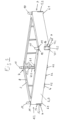
- the subject of the invention is a transport unit for pipette tips comprising a pipette tip box, a pipette tip carrier fitted to the pipette tip box and provided with pipette tips and at least one arrangement of a spacer according to one of Claims 1 to 15 or one of the above embodiments and one placed on the pipette tip carrier Spacers attached and provided with pipette tips, further pipette tip carrier.
- the transport unit is formed by placing one or more arrangements of a spacer with a pipette tip carrier fitted thereon, which is provided with pipette tip carriers, on a pipette tip box and a pipette tip carrier fitted thereon, which is provided with pipette tips.
- the at least one spacer keeps the pipette tips at a distance from one another in pipette tip carriers arranged one above the other, so that they can engage in one another without jamming one another. This way will achieves a space-saving and compact transport unit.
- the transport unit can also be used to store the pipette tips.
- a cover is placed on a pipette tip carrier or on a spacer placed on a pipette tip carrier.
- the transport unit is covered at the top by the lid and protected from contamination.
- the cover When the cover is placed on a pipette tip carrier, projecting slightly upwards over the pipette tips inserted therein, the cover can be hood-like or have indentations on the underside to accommodate the protruding parts of the pipette tips.
- the cover When the cover is placed on a spacer, it can be plate-shaped or hood-shaped.
- the subject of the invention is the use of a spacer according to one of Claims 1 to 15 or one of the above embodiments for forming a stack of pipette tip carriers which are kept at a distance from one another by means of spacers and are provided with pipette tips.
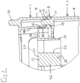
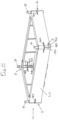
- a spacer 1.1 has a peripheral side wall 2, which forms a substantially vertical frame 3 with two longitudinal and two transverse sides. At the lower edge the spacer has a horizontal base 4 for supporting on a top of a pipette tip support 5.
- the horizontal base 4 comprises a shoulder 6.1 on each corner 7 and three shoulders 6.2 on each longitudinal side of the frame.
- the spacer 1.1 has an inwardly projecting circumferential flange 8.
- the top of the flange 8 is a horizontal support surface 9 for supporting another pipette tip support 5 on the underside.
- each spigot 10 is located in a recess 11 at the top of the flange 8 and has a conical socket 12 located within the recess 11 at the lower end. Furthermore, each pin 10 tapers towards the upper end.
- the side wall 2 has an inner radius 13 on the inside and an outer radius 14 on the outside.
- the spacer 1.1 has bending elements 15.1 in the form of cylindrical shells 16, which are arranged at a distance from the side wall 2 within the frame 3 and are integrally connected to the flange 8 at their arcuate upper edge 17.
- the cylindrical shells 16 have two vertical lateral edges 18, 19. Their lower edge 20 in the shape of a circular arc is arranged at the same level as the base 4 of the spacer 1.1 or is offset slightly upwards in this regard. Furthermore, the cylindrical shells 16 have a run-in bevel 21 on the lower edge on the inside.
- the spacer 1.1 is preferably made in one piece from plastic.
- the spacer 1.1 preferably consists of one or more plastics. It is preferably injection molded.
- the plastics polypropylene (PP), polyethylene (PE), polycarbonate (PC), acrylonitrile butadiene styrene copolymers (ABS) or polystyrene (PS) can be used.
- Polypropylene is preferably used as a particularly inexpensive plastic.
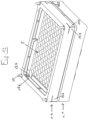
- a pipette tip carrier 5 has an essentially plate-shaped base body 22 with a multiplicity of holes 23 which extend from the upper side 24 to the underside 25 of the base body 22 .
- the holes 23 are regularly arranged in rows and columns of a matrix. In the example it is 96.
- the pipette tip carrier 5 has two long edges and two short edges. At a small distance from the long edges, it has plate-shaped gripping edges 26, 27, 28 which are parallel to these and project up from the upper side 24.
- the pipette tip carrier 5 has an edge 29 running around the base body 22 with a flat upper contact surface 30 and a flat lower contact surface 31.
- the upper contact surface 30 is slightly below the upper side 24 of the base body 22 and the lower contact surface 31 is slightly above the underside 25 of the body 22 (cf. 3 ).
- the plate-shaped base body 22 has radii 32 above the peripheral edge 29 and the peripheral edge 29 has through-holes 33 .
- the radii 32 and the cylindrical shells 16 are designed such that the cylindrical shells 16 are slightly deflected outwards by the radii 32 or rest against one another without play by partially inserting a pipette tip carrier 5 from below into the peripheral side wall 2 .
- the pipette tip carrier 5 is placed or clamped onto the upper side of the lower spacer 1.1.
- Each bore 33 has a conical section at the bottom and a cylindrical section adjacent thereto.
- the dimensions of the bores 33 are chosen such that the pins 10 of the spacer 1.1 can be pressed into them.
- the conical sections form insertion bevels that facilitate the insertion of the pins 10 into the bores 33 .
- tapers on the upper ends of the pins 10 facilitate insertion into the bores 33.
- the base body 22 is designed as a pocket plate.
- the holes 23 are formed in quiver- or sleeve-shaped structures 34 that are laterally are connected to each other by webs 35 and at the upper edge by a plate 36.
- An apron 37 runs around the outside of the plate 36 and the peripheral edge 29 protrudes outwards from the lower edge of the apron 37 (cf. figure 3 ).
- the pipette tip carrier 5 can also be designed as a web plate, with a thin plate having a large number of holes on the underside having webs enclosing the holes.
- the pipette tip carrier 5 can also be solid, i.e. without cavities outside of the holes 23 and bores 31.
- Pipette tips 38 can be inserted into the holes 23 from above and are supported by a collar 39 on the edge of the holes.
- the pipette tip carrier 5 is preferably manufactured in one piece. Furthermore, it is preferably made of plastic. It is preferably injection molded. In particular, the plastics polypropylene (PP), polycarbonate (PC), acrylonitrile butadiene styrene copolymers (ABS), polystyrene (PS) can be used for this.
- PP polypropylene
- PC polycarbonate
- ABS acrylonitrile butadiene styrene copolymers
- PS polystyrene
- the pipette tip carrier 5 is pressed with the bores 33 onto the pegs 10 of the lower spacer 1.1, so that the upper section of the pegs 10 of the lower spacer 1.1 projects upwards with respect to the base body 22 of the pipette tip carrier 5.
- the pins 10 can also be inserted into the bores 33 with play.
- the upper spacer 1.1 rests with its base 4 outside the gripping edges 26, 27, 28 on the upper contact surface 30 of the pipette tip carrier 5 and the lower spacer 1.1 rests with its support surface 9 on the lower contact surface 31 of the pipette tip carrier 5.
- the protruding sections of the pins 10 are inserted into the peripheral side wall 2 of the upper spacer 1.1 and the cylindrical shells 16 or spiral springs 15.1 of the upper spacer 1.1 rest against the radii 32 of the pipette tip carrier 5, which the lower spacer 1.1 carries. by slight Exact centering of the spacer 1.1 on the pipette tip carrier 5 and stable stacking is achieved by bending the spiral springs 15.1.
- the pins 10 have a press fit in the bores 33 or are guided in them without play.
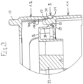
- the spacer 1.2 of Figures 5 to 7 differs from the one previously described in that at each corner 7, instead of a cylindrical shell 16, there are two vertical slots 40.1, 40.2, which start from the lower edge of the side wall 2 and end below the upper edge of the side wall 2. In the example, they end approximately halfway up the side wall 2.
- the two vertical slots 40.1, 40.2 are formed symmetrically with respect to the respective corner 7.
- the vertical slots 40.1, 40.2 each extend from the inside to the outside of the side wall 2.
- the area between the two vertical slots forms a bending element 15.2 in the form of a bending spring.
- the inner radius 13 at the corners 7 of the side wall 2 corresponds to the radius of the pin 9 or slightly exceeds it.
- the pegs 10 and the corners 7 of the spacer 1.2 are designed in such a way that the pegs 10 of another structurally identical spacer 1.2 or 1.1 can be inserted into the peripheral side wall 2 from below and adhere to the inner radii 13 of the corners 7, with the bending elements 15.2 invest. In this way, the spacers 1.2 or 1.2 and 1.1 are precisely centered on one another and stable stack formation is achieved.
- the spacer 1.2 is placed with its base 4 on a pipette tip carrier 5.
- the pipette tip carrier 5 is preferably placed on the support surface 9 of another spacer 1.2 of the same construction.
- the pipette tip carrier 5 is placed on the support surface 9 of a spacer 1.1, since the various exemplary embodiments can also be combined with one another.
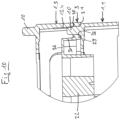
- the spacer 1.3 from Figures 8 to 10 differs from the one previously described in that it has only a single vertical slot 40.3 at each of the corners 7, which starts at the lower edge of the side wall 2 and ends at a distance from the upper edge of the side wall 2, approximately halfway up the side wall 2
- the vertical slots 40.3 are located in the middle of the corner 7, respectively.
- the areas adjoining the slot 40.3 form bending elements 15.3, 15.4, which can be slightly bent outwards by pins 10 of a further spacer 1.3, 1.2 or 1.1 inserted from below.
- the spacer 1.4 from Figures 11 to 13 differs from that previously described in that at each corner 7 there is a horizontal slot 40.4 in addition to the vertical slot 40.3.
- the horizontal slit 40.4 extends from the upper end of the vertical slit 40.3 on both sides a little into the adjoining transverse sides and longitudinal sides of the spacer 1.4.
- the horizontal slit 40.4 increases the flexural softness of the flexural elements 15.5, 15.6 adjoining the vertical slit.
Landscapes
- Chemical & Material Sciences (AREA)
- Health & Medical Sciences (AREA)
- Clinical Laboratory Science (AREA)
- Chemical Kinetics & Catalysis (AREA)
- Analytical Chemistry (AREA)
- Dispersion Chemistry (AREA)
- Devices For Use In Laboratory Experiments (AREA)
Priority Applications (3)
| Application Number | Priority Date | Filing Date | Title |
|---|---|---|---|
| EP21211549.7A EP4190452B1 (fr) | 2021-12-01 | 2021-12-01 | Espaceur permettant de maintenir les porte-pipettes empilés à distance les uns des autres |
| US18/714,876 US20250025881A1 (en) | 2021-12-01 | 2022-11-18 | Spacer for holding pipette tip carriers, which are stacked one over the other, spaced apart |
| PCT/EP2022/082451 WO2023099243A1 (fr) | 2021-12-01 | 2022-11-18 | Entretoise pour maintenir espacés des supports de pointes de pipette qui sont empilés les uns sur les autres |
Applications Claiming Priority (1)
| Application Number | Priority Date | Filing Date | Title |
|---|---|---|---|
| EP21211549.7A EP4190452B1 (fr) | 2021-12-01 | 2021-12-01 | Espaceur permettant de maintenir les porte-pipettes empilés à distance les uns des autres |
Publications (2)
| Publication Number | Publication Date |
|---|---|
| EP4190452A1 true EP4190452A1 (fr) | 2023-06-07 |
| EP4190452B1 EP4190452B1 (fr) | 2024-07-24 |
Family
ID=78820823
Family Applications (1)
| Application Number | Title | Priority Date | Filing Date |
|---|---|---|---|
| EP21211549.7A Active EP4190452B1 (fr) | 2021-12-01 | 2021-12-01 | Espaceur permettant de maintenir les porte-pipettes empilés à distance les uns des autres |
Country Status (3)
| Country | Link |
|---|---|
| US (1) | US20250025881A1 (fr) |
| EP (1) | EP4190452B1 (fr) |
| WO (1) | WO2023099243A1 (fr) |
Cited By (2)
| Publication number | Priority date | Publication date | Assignee | Title |
|---|---|---|---|---|
| EP4491276A1 (fr) * | 2024-04-11 | 2025-01-15 | TECAN Trading AG | Porte-pointes de pipette de forme rectangulaire pour contenir une pluralité de pointes de pipette |
| EP4491275A1 (fr) | 2024-04-11 | 2025-01-15 | TECAN Trading AG | Espaceur en forme de cadre pour porte-pointes de pipette |
Families Citing this family (1)
| Publication number | Priority date | Publication date | Assignee | Title |
|---|---|---|---|---|
| USD1112806S1 (en) * | 2024-11-15 | 2026-02-10 | Cytiva Us Llc | Tangential flow filtration cassette |
Citations (4)
| Publication number | Priority date | Publication date | Assignee | Title |
|---|---|---|---|---|
| DE202014100076U1 (de) * | 2014-01-09 | 2014-01-28 | Tecan Trading Ag | Abstandhalter für übereinander gestapelte Pipettenspitzen-Träger |
| EP2784076A1 (fr) | 2009-10-28 | 2014-10-01 | Joyant Pharmaceuticals, Inc. | Mimétiques de SMAC dimère |
| EP2839880A1 (fr) | 2013-08-20 | 2015-02-25 | Eppendorf Ag | Support pour embouts de pipette |
| EP2848308B1 (fr) | 2013-12-20 | 2018-09-05 | Tecan Trading AG | Écarteur pour support pour pointes de pipettes empilées les unes sur les autres |
-
2021
- 2021-12-01 EP EP21211549.7A patent/EP4190452B1/fr active Active
-
2022
- 2022-11-18 US US18/714,876 patent/US20250025881A1/en active Pending
- 2022-11-18 WO PCT/EP2022/082451 patent/WO2023099243A1/fr not_active Ceased
Patent Citations (4)
| Publication number | Priority date | Publication date | Assignee | Title |
|---|---|---|---|---|
| EP2784076A1 (fr) | 2009-10-28 | 2014-10-01 | Joyant Pharmaceuticals, Inc. | Mimétiques de SMAC dimère |
| EP2839880A1 (fr) | 2013-08-20 | 2015-02-25 | Eppendorf Ag | Support pour embouts de pipette |
| EP2848308B1 (fr) | 2013-12-20 | 2018-09-05 | Tecan Trading AG | Écarteur pour support pour pointes de pipettes empilées les unes sur les autres |
| DE202014100076U1 (de) * | 2014-01-09 | 2014-01-28 | Tecan Trading Ag | Abstandhalter für übereinander gestapelte Pipettenspitzen-Träger |
Cited By (2)
| Publication number | Priority date | Publication date | Assignee | Title |
|---|---|---|---|---|
| EP4491276A1 (fr) * | 2024-04-11 | 2025-01-15 | TECAN Trading AG | Porte-pointes de pipette de forme rectangulaire pour contenir une pluralité de pointes de pipette |
| EP4491275A1 (fr) | 2024-04-11 | 2025-01-15 | TECAN Trading AG | Espaceur en forme de cadre pour porte-pointes de pipette |
Also Published As
| Publication number | Publication date |
|---|---|
| US20250025881A1 (en) | 2025-01-23 |
| WO2023099243A1 (fr) | 2023-06-08 |
| EP4190452B1 (fr) | 2024-07-24 |
Similar Documents
| Publication | Publication Date | Title |
|---|---|---|
| WO2023099243A1 (fr) | Entretoise pour maintenir espacés des supports de pointes de pipette qui sont empilés les uns sur les autres | |
| EP3354589B1 (fr) | Structure de support permettant de supporter simultanément une pluralité de récipients pour substances destinées à des applications médicales, pharmaceutiques ou cosmétiques, élément de transport et récipient de transport ou d'emballage dotés de ladite structure | |
| EP2789389B1 (fr) | Dispositif pour stockage et pour fournir des embouts de pipette | |
| DE102009006511B4 (de) | Träger für Pipettenspitzen | |
| EP2848308B1 (fr) | Écarteur pour support pour pointes de pipettes empilées les unes sur les autres | |
| DE60224673T2 (de) | Kulturflasche | |
| DE69837717T2 (de) | Platten für spielbausets | |
| EP2355932B1 (fr) | Support pour une unité d'échantillonnage | |
| EP3320975B1 (fr) | Dispositif de mise en place d'embouts de pipette | |
| EP3500661B1 (fr) | Insert de culture de cellules et dispositif de mise en culture des cellules | |
| EP0414644A2 (fr) | Dispositif de rapport en forme de chaîne à tubes pour supporter un récipient tubulaire | |
| EP0578153B1 (fr) | Plateau de propagation, en particulier pour plantes forestières | |
| EP4019137A1 (fr) | Cadre permettant de loger une plaque de support pour pointes de pipette | |
| DE3037892C2 (de) | Stapel- und wendbare Blockform zur Käseherstellung | |
| EP4331723B1 (fr) | Ensemble comprenant une microplaque, un couvercle et un dispositif de libération d'une liaison encliquetable entre la microplaque et le couvercle | |
| EP3257619B1 (fr) | Magasin pour vis | |
| WO2026068308A1 (fr) | Support pour soutenir une pluralité de pointes de pipette | |
| EP1014374A1 (fr) | Contenair, pour stockage d'un disque circulaire, contenant de l'information, qui peut être fermer, spéciallement pour un disque compact contenant de l'information numérique | |
| DE202014100076U1 (de) | Abstandhalter für übereinander gestapelte Pipettenspitzen-Träger | |
| EP4327943A1 (fr) | Microplaque | |
| EP0428961A1 (fr) | Douille d'ancrage dans le sol pour la réception d'un pied d'un agrès sportif | |
| DE29922006U1 (de) | Verbindungselement für Trennwände zur Facheinteilung einer Schublade | |
| EP4327944A1 (fr) | Microplaque | |
| WO2023110327A1 (fr) | Récipient de réception microfluidique pour recevoir un récipient de réactif, récipient de réactif et dispositif microfluidique | |
| DE29610935U1 (de) | Transport- und Kultivationspalette |
Legal Events
| Date | Code | Title | Description |
|---|---|---|---|
| PUAI | Public reference made under article 153(3) epc to a published international application that has entered the european phase |
Free format text: ORIGINAL CODE: 0009012 |
|
| STAA | Information on the status of an ep patent application or granted ep patent |
Free format text: STATUS: THE APPLICATION HAS BEEN PUBLISHED |
|
| AK | Designated contracting states |
Kind code of ref document: A1 Designated state(s): AL AT BE BG CH CY CZ DE DK EE ES FI FR GB GR HR HU IE IS IT LI LT LU LV MC MK MT NL NO PL PT RO RS SE SI SK SM TR |
|
| STAA | Information on the status of an ep patent application or granted ep patent |
Free format text: STATUS: REQUEST FOR EXAMINATION WAS MADE |
|
| 17P | Request for examination filed |
Effective date: 20231207 |
|
| RBV | Designated contracting states (corrected) |
Designated state(s): AL AT BE BG CH CY CZ DE DK EE ES FI FR GB GR HR HU IE IS IT LI LT LU LV MC MK MT NL NO PL PT RO RS SE SI SK SM TR |
|
| GRAP | Despatch of communication of intention to grant a patent |
Free format text: ORIGINAL CODE: EPIDOSNIGR1 |
|
| STAA | Information on the status of an ep patent application or granted ep patent |
Free format text: STATUS: GRANT OF PATENT IS INTENDED |
|
| RIC1 | Information provided on ipc code assigned before grant |
Ipc: B01L 3/02 20060101ALI20240220BHEP Ipc: B01L 9/00 20060101AFI20240220BHEP |
|
| INTG | Intention to grant announced |
Effective date: 20240312 |
|
| GRAS | Grant fee paid |
Free format text: ORIGINAL CODE: EPIDOSNIGR3 |
|
| GRAA | (expected) grant |
Free format text: ORIGINAL CODE: 0009210 |
|
| STAA | Information on the status of an ep patent application or granted ep patent |
Free format text: STATUS: THE PATENT HAS BEEN GRANTED |
|
| AK | Designated contracting states |
Kind code of ref document: B1 Designated state(s): AL AT BE BG CH CY CZ DE DK EE ES FI FR GB GR HR HU IE IS IT LI LT LU LV MC MK MT NL NO PL PT RO RS SE SI SK SM TR |
|
| REG | Reference to a national code |
Ref country code: GB Ref legal event code: FG4D Free format text: NOT ENGLISH |
|
| REG | Reference to a national code |
Ref country code: CH Ref legal event code: EP |
|
| REG | Reference to a national code |
Ref country code: DE Ref legal event code: R096 Ref document number: 502021004483 Country of ref document: DE |
|
| REG | Reference to a national code |
Ref country code: IE Ref legal event code: FG4D Free format text: LANGUAGE OF EP DOCUMENT: GERMAN |
|
| REG | Reference to a national code |
Ref country code: LT Ref legal event code: MG9D |
|
| REG | Reference to a national code |
Ref country code: NL Ref legal event code: MP Effective date: 20240724 |
|
| PG25 | Lapsed in a contracting state [announced via postgrant information from national office to epo] |
Ref country code: PT Free format text: LAPSE BECAUSE OF FAILURE TO SUBMIT A TRANSLATION OF THE DESCRIPTION OR TO PAY THE FEE WITHIN THE PRESCRIBED TIME-LIMIT Effective date: 20241125 |
|
| PG25 | Lapsed in a contracting state [announced via postgrant information from national office to epo] |
Ref country code: NL Free format text: LAPSE BECAUSE OF FAILURE TO SUBMIT A TRANSLATION OF THE DESCRIPTION OR TO PAY THE FEE WITHIN THE PRESCRIBED TIME-LIMIT Effective date: 20240724 |
|
| PG25 | Lapsed in a contracting state [announced via postgrant information from national office to epo] |
Ref country code: PT Free format text: LAPSE BECAUSE OF FAILURE TO SUBMIT A TRANSLATION OF THE DESCRIPTION OR TO PAY THE FEE WITHIN THE PRESCRIBED TIME-LIMIT Effective date: 20241125 Ref country code: NL Free format text: LAPSE BECAUSE OF FAILURE TO SUBMIT A TRANSLATION OF THE DESCRIPTION OR TO PAY THE FEE WITHIN THE PRESCRIBED TIME-LIMIT Effective date: 20240724 |
|
| PG25 | Lapsed in a contracting state [announced via postgrant information from national office to epo] |
Ref country code: NO Free format text: LAPSE BECAUSE OF FAILURE TO SUBMIT A TRANSLATION OF THE DESCRIPTION OR TO PAY THE FEE WITHIN THE PRESCRIBED TIME-LIMIT Effective date: 20241024 |
|
| PG25 | Lapsed in a contracting state [announced via postgrant information from national office to epo] |
Ref country code: FI Free format text: LAPSE BECAUSE OF FAILURE TO SUBMIT A TRANSLATION OF THE DESCRIPTION OR TO PAY THE FEE WITHIN THE PRESCRIBED TIME-LIMIT Effective date: 20240724 Ref country code: GR Free format text: LAPSE BECAUSE OF FAILURE TO SUBMIT A TRANSLATION OF THE DESCRIPTION OR TO PAY THE FEE WITHIN THE PRESCRIBED TIME-LIMIT Effective date: 20241025 Ref country code: PL Free format text: LAPSE BECAUSE OF FAILURE TO SUBMIT A TRANSLATION OF THE DESCRIPTION OR TO PAY THE FEE WITHIN THE PRESCRIBED TIME-LIMIT Effective date: 20240724 |
|
| PG25 | Lapsed in a contracting state [announced via postgrant information from national office to epo] |
Ref country code: BG Free format text: LAPSE BECAUSE OF FAILURE TO SUBMIT A TRANSLATION OF THE DESCRIPTION OR TO PAY THE FEE WITHIN THE PRESCRIBED TIME-LIMIT Effective date: 20240724 |
|
| PG25 | Lapsed in a contracting state [announced via postgrant information from national office to epo] |
Ref country code: LV Free format text: LAPSE BECAUSE OF FAILURE TO SUBMIT A TRANSLATION OF THE DESCRIPTION OR TO PAY THE FEE WITHIN THE PRESCRIBED TIME-LIMIT Effective date: 20240724 |
|
| PG25 | Lapsed in a contracting state [announced via postgrant information from national office to epo] |
Ref country code: IS Free format text: LAPSE BECAUSE OF FAILURE TO SUBMIT A TRANSLATION OF THE DESCRIPTION OR TO PAY THE FEE WITHIN THE PRESCRIBED TIME-LIMIT Effective date: 20241124 |
|
| PG25 | Lapsed in a contracting state [announced via postgrant information from national office to epo] |
Ref country code: HR Free format text: LAPSE BECAUSE OF FAILURE TO SUBMIT A TRANSLATION OF THE DESCRIPTION OR TO PAY THE FEE WITHIN THE PRESCRIBED TIME-LIMIT Effective date: 20240724 |
|
| PG25 | Lapsed in a contracting state [announced via postgrant information from national office to epo] |
Ref country code: RS Free format text: LAPSE BECAUSE OF FAILURE TO SUBMIT A TRANSLATION OF THE DESCRIPTION OR TO PAY THE FEE WITHIN THE PRESCRIBED TIME-LIMIT Effective date: 20241024 Ref country code: ES Free format text: LAPSE BECAUSE OF FAILURE TO SUBMIT A TRANSLATION OF THE DESCRIPTION OR TO PAY THE FEE WITHIN THE PRESCRIBED TIME-LIMIT Effective date: 20240724 |
|
| PG25 | Lapsed in a contracting state [announced via postgrant information from national office to epo] |
Ref country code: RS Free format text: LAPSE BECAUSE OF FAILURE TO SUBMIT A TRANSLATION OF THE DESCRIPTION OR TO PAY THE FEE WITHIN THE PRESCRIBED TIME-LIMIT Effective date: 20241024 Ref country code: PL Free format text: LAPSE BECAUSE OF FAILURE TO SUBMIT A TRANSLATION OF THE DESCRIPTION OR TO PAY THE FEE WITHIN THE PRESCRIBED TIME-LIMIT Effective date: 20240724 Ref country code: NO Free format text: LAPSE BECAUSE OF FAILURE TO SUBMIT A TRANSLATION OF THE DESCRIPTION OR TO PAY THE FEE WITHIN THE PRESCRIBED TIME-LIMIT Effective date: 20241024 Ref country code: LV Free format text: LAPSE BECAUSE OF FAILURE TO SUBMIT A TRANSLATION OF THE DESCRIPTION OR TO PAY THE FEE WITHIN THE PRESCRIBED TIME-LIMIT Effective date: 20240724 Ref country code: IS Free format text: LAPSE BECAUSE OF FAILURE TO SUBMIT A TRANSLATION OF THE DESCRIPTION OR TO PAY THE FEE WITHIN THE PRESCRIBED TIME-LIMIT Effective date: 20241124 Ref country code: HR Free format text: LAPSE BECAUSE OF FAILURE TO SUBMIT A TRANSLATION OF THE DESCRIPTION OR TO PAY THE FEE WITHIN THE PRESCRIBED TIME-LIMIT Effective date: 20240724 Ref country code: GR Free format text: LAPSE BECAUSE OF FAILURE TO SUBMIT A TRANSLATION OF THE DESCRIPTION OR TO PAY THE FEE WITHIN THE PRESCRIBED TIME-LIMIT Effective date: 20241025 Ref country code: FI Free format text: LAPSE BECAUSE OF FAILURE TO SUBMIT A TRANSLATION OF THE DESCRIPTION OR TO PAY THE FEE WITHIN THE PRESCRIBED TIME-LIMIT Effective date: 20240724 Ref country code: ES Free format text: LAPSE BECAUSE OF FAILURE TO SUBMIT A TRANSLATION OF THE DESCRIPTION OR TO PAY THE FEE WITHIN THE PRESCRIBED TIME-LIMIT Effective date: 20240724 Ref country code: BG Free format text: LAPSE BECAUSE OF FAILURE TO SUBMIT A TRANSLATION OF THE DESCRIPTION OR TO PAY THE FEE WITHIN THE PRESCRIBED TIME-LIMIT Effective date: 20240724 |
|
| PG25 | Lapsed in a contracting state [announced via postgrant information from national office to epo] |
Ref country code: SM Free format text: LAPSE BECAUSE OF FAILURE TO SUBMIT A TRANSLATION OF THE DESCRIPTION OR TO PAY THE FEE WITHIN THE PRESCRIBED TIME-LIMIT Effective date: 20240724 Ref country code: DK Free format text: LAPSE BECAUSE OF FAILURE TO SUBMIT A TRANSLATION OF THE DESCRIPTION OR TO PAY THE FEE WITHIN THE PRESCRIBED TIME-LIMIT Effective date: 20240724 Ref country code: RO Free format text: LAPSE BECAUSE OF FAILURE TO SUBMIT A TRANSLATION OF THE DESCRIPTION OR TO PAY THE FEE WITHIN THE PRESCRIBED TIME-LIMIT Effective date: 20240724 |
|
| PG25 | Lapsed in a contracting state [announced via postgrant information from national office to epo] |
Ref country code: EE Free format text: LAPSE BECAUSE OF FAILURE TO SUBMIT A TRANSLATION OF THE DESCRIPTION OR TO PAY THE FEE WITHIN THE PRESCRIBED TIME-LIMIT Effective date: 20240724 |
|
| PG25 | Lapsed in a contracting state [announced via postgrant information from national office to epo] |
Ref country code: CZ Free format text: LAPSE BECAUSE OF FAILURE TO SUBMIT A TRANSLATION OF THE DESCRIPTION OR TO PAY THE FEE WITHIN THE PRESCRIBED TIME-LIMIT Effective date: 20240724 |
|
| REG | Reference to a national code |
Ref country code: DE Ref legal event code: R097 Ref document number: 502021004483 Country of ref document: DE |
|
| PG25 | Lapsed in a contracting state [announced via postgrant information from national office to epo] |
Ref country code: SK Free format text: LAPSE BECAUSE OF FAILURE TO SUBMIT A TRANSLATION OF THE DESCRIPTION OR TO PAY THE FEE WITHIN THE PRESCRIBED TIME-LIMIT Effective date: 20240724 Ref country code: IT Free format text: LAPSE BECAUSE OF FAILURE TO SUBMIT A TRANSLATION OF THE DESCRIPTION OR TO PAY THE FEE WITHIN THE PRESCRIBED TIME-LIMIT Effective date: 20240724 |
|
| PLBE | No opposition filed within time limit |
Free format text: ORIGINAL CODE: 0009261 |
|
| STAA | Information on the status of an ep patent application or granted ep patent |
Free format text: STATUS: NO OPPOSITION FILED WITHIN TIME LIMIT |
|
| 26N | No opposition filed |
Effective date: 20250425 |
|
| PG25 | Lapsed in a contracting state [announced via postgrant information from national office to epo] |
Ref country code: MC Free format text: LAPSE BECAUSE OF FAILURE TO SUBMIT A TRANSLATION OF THE DESCRIPTION OR TO PAY THE FEE WITHIN THE PRESCRIBED TIME-LIMIT Effective date: 20240724 |
|
| REG | Reference to a national code |
Ref country code: CH Ref legal event code: PL |
|
| PG25 | Lapsed in a contracting state [announced via postgrant information from national office to epo] |
Ref country code: LU Free format text: LAPSE BECAUSE OF NON-PAYMENT OF DUE FEES Effective date: 20241201 |
|
| PG25 | Lapsed in a contracting state [announced via postgrant information from national office to epo] |
Ref country code: SE Free format text: LAPSE BECAUSE OF FAILURE TO SUBMIT A TRANSLATION OF THE DESCRIPTION OR TO PAY THE FEE WITHIN THE PRESCRIBED TIME-LIMIT Effective date: 20240724 |
|
| REG | Reference to a national code |
Ref country code: BE Ref legal event code: MM Effective date: 20241231 |
|
| PG25 | Lapsed in a contracting state [announced via postgrant information from national office to epo] |
Ref country code: BE Free format text: LAPSE BECAUSE OF NON-PAYMENT OF DUE FEES Effective date: 20241231 |
|
| PG25 | Lapsed in a contracting state [announced via postgrant information from national office to epo] |
Ref country code: CH Free format text: LAPSE BECAUSE OF NON-PAYMENT OF DUE FEES Effective date: 20241231 |
|
| PG25 | Lapsed in a contracting state [announced via postgrant information from national office to epo] |
Ref country code: IE Free format text: LAPSE BECAUSE OF NON-PAYMENT OF DUE FEES Effective date: 20241201 |
|
| PGFP | Annual fee paid to national office [announced via postgrant information from national office to epo] |
Ref country code: DE Payment date: 20251211 Year of fee payment: 5 |
|
| PGFP | Annual fee paid to national office [announced via postgrant information from national office to epo] |
Ref country code: GB Payment date: 20251219 Year of fee payment: 5 |
|
| PGFP | Annual fee paid to national office [announced via postgrant information from national office to epo] |
Ref country code: AT Payment date: 20260113 Year of fee payment: 5 |
|
| PGFP | Annual fee paid to national office [announced via postgrant information from national office to epo] |
Ref country code: FR Payment date: 20251229 Year of fee payment: 5 |
|
| PG25 | Lapsed in a contracting state [announced via postgrant information from national office to epo] |
Ref country code: CY Free format text: LAPSE BECAUSE OF FAILURE TO SUBMIT A TRANSLATION OF THE DESCRIPTION OR TO PAY THE FEE WITHIN THE PRESCRIBED TIME-LIMIT; INVALID AB INITIO Effective date: 20211201 |