EP4491299A1 - Verfahren zur herstellung eines kreuzrillen-gleichlaufgelenks und werkzeug für das verfahren - Google Patents
Verfahren zur herstellung eines kreuzrillen-gleichlaufgelenks und werkzeug für das verfahren Download PDFInfo
- Publication number
- EP4491299A1 EP4491299A1 EP23382724.5A EP23382724A EP4491299A1 EP 4491299 A1 EP4491299 A1 EP 4491299A1 EP 23382724 A EP23382724 A EP 23382724A EP 4491299 A1 EP4491299 A1 EP 4491299A1
- Authority
- EP
- European Patent Office
- Prior art keywords
- punch
- cross
- piece
- segments
- procedure
- Prior art date
- Legal status (The legal status is an assumption and is not a legal conclusion. Google has not performed a legal analysis and makes no representation as to the accuracy of the status listed.)
- Withdrawn
Links
Images

Classifications
-
- F—MECHANICAL ENGINEERING; LIGHTING; HEATING; WEAPONS; BLASTING
- F16—ENGINEERING ELEMENTS AND UNITS; GENERAL MEASURES FOR PRODUCING AND MAINTAINING EFFECTIVE FUNCTIONING OF MACHINES OR INSTALLATIONS; THERMAL INSULATION IN GENERAL
- F16D—COUPLINGS FOR TRANSMITTING ROTATION; CLUTCHES; BRAKES
- F16D3/00—Yielding couplings, i.e. with means permitting movement between the connected parts during the drive
- F16D3/16—Universal joints in which flexibility is produced by means of pivots or sliding or rolling connecting parts
- F16D3/20—Universal joints in which flexibility is produced by means of pivots or sliding or rolling connecting parts one coupling part entering a sleeve of the other coupling part and connected thereto by sliding or rolling members
- F16D3/22—Universal joints in which flexibility is produced by means of pivots or sliding or rolling connecting parts one coupling part entering a sleeve of the other coupling part and connected thereto by sliding or rolling members the rolling members being balls, rollers, or the like, guided in grooves or sockets in both coupling parts
- F16D3/223—Universal joints in which flexibility is produced by means of pivots or sliding or rolling connecting parts one coupling part entering a sleeve of the other coupling part and connected thereto by sliding or rolling members the rolling members being balls, rollers, or the like, guided in grooves or sockets in both coupling parts the rolling members being guided in grooves in both coupling parts
-
- B—PERFORMING OPERATIONS; TRANSPORTING
- B21—MECHANICAL METAL-WORKING WITHOUT ESSENTIALLY REMOVING MATERIAL; PUNCHING METAL
- B21J—FORGING; HAMMERING; PRESSING METAL; RIVETING; FORGE FURNACES
- B21J13/00—Details of machines for forging, pressing, or hammering
- B21J13/02—Dies or mountings therefor
-
- B—PERFORMING OPERATIONS; TRANSPORTING
- B21—MECHANICAL METAL-WORKING WITHOUT ESSENTIALLY REMOVING MATERIAL; PUNCHING METAL
- B21J—FORGING; HAMMERING; PRESSING METAL; RIVETING; FORGE FURNACES
- B21J5/00—Methods for forging, hammering, or pressing; Special equipment or accessories therefor
- B21J5/06—Methods for forging, hammering, or pressing; Special equipment or accessories therefor for performing particular operations
- B21J5/12—Forming profiles on internal or external surfaces
-
- B—PERFORMING OPERATIONS; TRANSPORTING
- B21—MECHANICAL METAL-WORKING WITHOUT ESSENTIALLY REMOVING MATERIAL; PUNCHING METAL
- B21K—MAKING FORGED OR PRESSED METAL PRODUCTS, e.g. HORSE-SHOES, RIVETS, BOLTS OR WHEELS
- B21K1/00—Making machine elements
- B21K1/76—Making machine elements elements not mentioned in one of the preceding groups
- B21K1/762—Coupling members for conveying mechanical motion, e.g. universal joints
- B21K1/765—Outer elements of coupling members
-
- B—PERFORMING OPERATIONS; TRANSPORTING
- B21—MECHANICAL METAL-WORKING WITHOUT ESSENTIALLY REMOVING MATERIAL; PUNCHING METAL
- B21K—MAKING FORGED OR PRESSED METAL PRODUCTS, e.g. HORSE-SHOES, RIVETS, BOLTS OR WHEELS
- B21K21/00—Making hollow articles not covered by a single preceding sub-group
- B21K21/08—Shaping hollow articles with different cross-section in longitudinal direction, e.g. nozzles, spark-plugs
- B21K21/10—Shaping hollow articles with different cross-section in longitudinal direction, e.g. nozzles, spark-plugs cone-shaped or bell-shaped articles, e.g. insulator caps
-
- F—MECHANICAL ENGINEERING; LIGHTING; HEATING; WEAPONS; BLASTING
- F16—ENGINEERING ELEMENTS AND UNITS; GENERAL MEASURES FOR PRODUCING AND MAINTAINING EFFECTIVE FUNCTIONING OF MACHINES OR INSTALLATIONS; THERMAL INSULATION IN GENERAL
- F16D—COUPLINGS FOR TRANSMITTING ROTATION; CLUTCHES; BRAKES
- F16D3/00—Yielding couplings, i.e. with means permitting movement between the connected parts during the drive
- F16D3/16—Universal joints in which flexibility is produced by means of pivots or sliding or rolling connecting parts
- F16D3/20—Universal joints in which flexibility is produced by means of pivots or sliding or rolling connecting parts one coupling part entering a sleeve of the other coupling part and connected thereto by sliding or rolling members
- F16D3/22—Universal joints in which flexibility is produced by means of pivots or sliding or rolling connecting parts one coupling part entering a sleeve of the other coupling part and connected thereto by sliding or rolling members the rolling members being balls, rollers, or the like, guided in grooves or sockets in both coupling parts
- F16D3/223—Universal joints in which flexibility is produced by means of pivots or sliding or rolling connecting parts one coupling part entering a sleeve of the other coupling part and connected thereto by sliding or rolling members the rolling members being balls, rollers, or the like, guided in grooves or sockets in both coupling parts the rolling members being guided in grooves in both coupling parts
- F16D2003/22306—Universal joints in which flexibility is produced by means of pivots or sliding or rolling connecting parts one coupling part entering a sleeve of the other coupling part and connected thereto by sliding or rolling members the rolling members being balls, rollers, or the like, guided in grooves or sockets in both coupling parts the rolling members being guided in grooves in both coupling parts having counter tracks, i.e. ball track surfaces which diverge in opposite directions
-
- F—MECHANICAL ENGINEERING; LIGHTING; HEATING; WEAPONS; BLASTING
- F16—ENGINEERING ELEMENTS AND UNITS; GENERAL MEASURES FOR PRODUCING AND MAINTAINING EFFECTIVE FUNCTIONING OF MACHINES OR INSTALLATIONS; THERMAL INSULATION IN GENERAL
- F16D—COUPLINGS FOR TRANSMITTING ROTATION; CLUTCHES; BRAKES
- F16D2250/00—Manufacturing; Assembly
- F16D2250/0023—Shaping by pressure
Definitions
- This invention is framed within the technical field of couplings for the transmission of rotational movements, more specifically in that of the extensible couplings by putting one of the coupling parts into a sleeve of the other coupling part and attached to it by sliding or rotating organs.
- the invention is also falls within the technical field of the constituent parts of forging machines, specifically in that of forging tooling.
- the invention relates in particular to a procedure for obtaining a cross groove constant velocity (CV) joint, as well as to a forging tool required to carry out such procedure.
- CV constant velocity
- the joint is the part that contains the wheel hub or spindle and is attached to the suspension parts. Depending on the situation, it is usually called a constant velocity joint, outer race, boll, spindle, frame, or hub.
- the wheel and tire assembly are attached to the hub or spindle of the CV Joint, where the wheel rotates, while being held in a stable plane of motion by the stub axle/suspension assembly.
- joints of all sizes and shapes Its design differs to adapt to all types of application and suspension.
- the current production process of cross groove CV joints comprises a first sequence of operations aimed at obtaining a final forging part, which is subsequently subjected to a second sequence of operations to give rise to the final joint.
- This second sequence is usually performed on the end customer of the product.
- This first sequence comprises the following successive steps:
- This second sequence comprises:
- the first sequence of this process does not have a cold calibration stage, unlike the production of straight track stub shafts. This makes the second sequence necessary, where the forging part is roughed to form these tracks.
- document CN108838311A discloses a precision forging system for the development of external cups of cross-tracks belonging to a CV joint.
- the system uses a precision forging device that has a mold with a tapered guidepost surrounded by a set of printing punches where each segment has a surface in the shape of the track and recess where a spring keeps each segment in full contact with the guidepost.
- Document WO2019138872A1 discloses a forging device for external elements of CV joints.
- the device has a mechanism to finish tracing cross-tracks on the external element, by using a segmented punch.
- the mechanism deposits the external element in a die and receives the punch by means of a press.
- Document US5788578A is a system for making tracks in CV type joints that also proposes a tool for the calibration of these tracks by means of a segmented punch, where the gap between segments is destined to the contraction of the diameter of this at the time of removal.
- the first object of the invention is a procedure for obtaining a cross groove CV joint.
- the second object of the invention is a tool used in the procedure, more specifically a segmented expansive punch used in the cold calibration stage.
- the invention proposes an alternative to the state of the art where the final stage of obtaining the part in the form of a cup dispenses the machining process, which finishes the profile of the tracks. Instead, the invention proposes the realization of a cold calibration with the use of a tool consisting of an expansive punch, where a negative of each track is housed in a segment of that punch. This punch is used in a cold calibration stage where the final profile of each cross-track of the cup body is achieved.
- the procedure for obtaining a cross groove CV joint therefore comprises the following stages:
- the steps from induction heating to cold calibration, both inclusive, are performed by a robot.
- Some key features for the forging must be considered, such as the special geometry on the tracks to obtain. These have a conical-ellipse shape to avoid retentions in semi hot forging. The interior without retentions allows to forge the part with the same process used in other stub shafts with straight tracks. In addition, in the case of the cross-groove CV joint, the material transformation is greater than for those of straight tracks, due to its inner geometry. In the calibration of tracks not only the tracks are closed, but also an extrusion is made for the correct forming of the final part.
- Cross groove CV joint require more flexible segments, since having a greater retentions than other stub shafts the displacement of these segments is greater for the correct removal of the part.
- the segments require a deformation of approximately 5-6 mm for the system to work correctly, while in other stub shafts the necessary deformation is usually about 2-3 mm.
- the operation of the punch in the cold calibration is in such a way that when it is compressed against the inner face of the cup body, the negative of the tracks shapes each track in the piece, at the same time as due to the gap between segments (between 3-5 mm) in the removal of the punch, the wedge-shaped thrust bodies, when removed, allow the segment contraction, separating from the tracks and managing to extract the punch without causing damage.
- the punch also incorporates a notch that helps the deformation of each punch segment, reducing the risk of breakage during cold calibration operation.
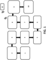
- the procedure therefore comprises the following successive steps:
- the procedure is completed in its final stages with washing and visual inspection (9) of the piece and with the shipment (10) of the joint (M) once completed.
- the steps from heating (3) to cold calibration (8), inclusive, are performed by a robot.
- This robot is governed by an external controller (CE), which controls these and all other stages of the procedure.
- CE external controller
- a pressure element and a mold are used, aimed at forming and final profiling of the cross-tracks (PC) of the joint (M).
- the pressure element consists of a punch (11).
- the punch (11) is pushed against the cup-shaped piece obtained after forging (4), blasting (6) and lubrication (7) and placed on the mold.
- the lubrication (7) step is carried out through an oiling procedure.
- it can be performed by a phosphate or polymerization procedures.
- the steel is previously stud-shape cut, with which the cutting (2) step is not necessary.
- the steel heating (3) is performed by induction.
- such heating is done by chamber oven.
- the punch (11), shown in figure 3 is of an expansive type and comprises at least one body divided into a plurality of segments (12) separated from each other by grooves (13), in such a way that each segment (12) collects the negative corresponding to the cross-track (PC) to be formed inside the cup-shaped piece.
- the punch (11) also includes an internal recess to obtain stresses below the yield limit.
- the incorporation of external recesses is also foreseen, which also contribute to an additional increase of the segments (12) flexibility.
- the geometry of the punch (11) is key.
- the formation of the cross-tracks (PC) requires that some segments (12) be more flexible, since having a greater retention than other joints, the displacement of these segments (12) is greater for the correct extraction of the piece from the mold.
Landscapes
- Engineering & Computer Science (AREA)
- Mechanical Engineering (AREA)
- General Engineering & Computer Science (AREA)
- Forging (AREA)
Priority Applications (1)
| Application Number | Priority Date | Filing Date | Title |
|---|---|---|---|
| EP23382724.5A EP4491299A1 (de) | 2023-07-14 | 2023-07-14 | Verfahren zur herstellung eines kreuzrillen-gleichlaufgelenks und werkzeug für das verfahren |
Applications Claiming Priority (1)
| Application Number | Priority Date | Filing Date | Title |
|---|---|---|---|
| EP23382724.5A EP4491299A1 (de) | 2023-07-14 | 2023-07-14 | Verfahren zur herstellung eines kreuzrillen-gleichlaufgelenks und werkzeug für das verfahren |
Publications (1)
| Publication Number | Publication Date |
|---|---|
| EP4491299A1 true EP4491299A1 (de) | 2025-01-15 |
Family
ID=87760603
Family Applications (1)
| Application Number | Title | Priority Date | Filing Date |
|---|---|---|---|
| EP23382724.5A Withdrawn EP4491299A1 (de) | 2023-07-14 | 2023-07-14 | Verfahren zur herstellung eines kreuzrillen-gleichlaufgelenks und werkzeug für das verfahren |
Country Status (1)
| Country | Link |
|---|---|
| EP (1) | EP4491299A1 (de) |
Citations (11)
| Publication number | Priority date | Publication date | Assignee | Title |
|---|---|---|---|---|
| US4694676A (en) * | 1982-07-28 | 1987-09-22 | General Motors Corporation | Method of manufacturing tri-pot universal joint housings |
| DE19639677A1 (de) * | 1995-09-27 | 1997-04-03 | Ntn Toyo Bearing Co Ltd | Verfahren und Vorrichtung zur Herstellung des äußeren Elements eines Universalgelenks mit Kreuznuten |
| US5788578A (en) | 1995-02-16 | 1998-08-04 | Ntn Corporation | Homokinetic joint having an outer ring formed with track grooves which have a constant effective depth |
| CN102861861A (zh) * | 2011-07-06 | 2013-01-09 | 张太良 | 球笼式万向节钟形壳精锻塑性成型工艺 |
| WO2013137256A1 (ja) * | 2012-03-12 | 2013-09-19 | Ntn株式会社 | 等速自在継手用外側継手部材の製造方法および外側継手部材 |
| DE102016216833A1 (de) * | 2016-09-06 | 2018-03-08 | Hirschvogel Umformtechnik Gmbh | Gleichlaufgelenkaußenbauteil |
| CN108838311A (zh) | 2018-06-28 | 2018-11-20 | 江苏创精锻有限公司 | 一种异形沟道钟形壳的冷锻成形模具 |
| CN109108193A (zh) * | 2018-06-28 | 2019-01-01 | 江苏创精锻有限公司 | 一种异形沟道钟形壳的锻造工艺 |
| WO2019138872A1 (ja) | 2018-01-09 | 2019-07-18 | Ntn株式会社 | 等速自在継手の外側継手部材の鍛造装置および鍛造方法 |
| US20200009627A1 (en) * | 2017-03-23 | 2020-01-09 | Bharat Forge Limited | Planet Carrier And A Process And Apparatus To Manufacture It |
| EP3417957B1 (de) * | 2016-02-16 | 2020-11-11 | NTN Corporation | Verfahren zum schmieden eines gelenkaussenteils eines gleichlaufgelenks |
-
2023
- 2023-07-14 EP EP23382724.5A patent/EP4491299A1/de not_active Withdrawn
Patent Citations (11)
| Publication number | Priority date | Publication date | Assignee | Title |
|---|---|---|---|---|
| US4694676A (en) * | 1982-07-28 | 1987-09-22 | General Motors Corporation | Method of manufacturing tri-pot universal joint housings |
| US5788578A (en) | 1995-02-16 | 1998-08-04 | Ntn Corporation | Homokinetic joint having an outer ring formed with track grooves which have a constant effective depth |
| DE19639677A1 (de) * | 1995-09-27 | 1997-04-03 | Ntn Toyo Bearing Co Ltd | Verfahren und Vorrichtung zur Herstellung des äußeren Elements eines Universalgelenks mit Kreuznuten |
| CN102861861A (zh) * | 2011-07-06 | 2013-01-09 | 张太良 | 球笼式万向节钟形壳精锻塑性成型工艺 |
| WO2013137256A1 (ja) * | 2012-03-12 | 2013-09-19 | Ntn株式会社 | 等速自在継手用外側継手部材の製造方法および外側継手部材 |
| EP3417957B1 (de) * | 2016-02-16 | 2020-11-11 | NTN Corporation | Verfahren zum schmieden eines gelenkaussenteils eines gleichlaufgelenks |
| DE102016216833A1 (de) * | 2016-09-06 | 2018-03-08 | Hirschvogel Umformtechnik Gmbh | Gleichlaufgelenkaußenbauteil |
| US20200009627A1 (en) * | 2017-03-23 | 2020-01-09 | Bharat Forge Limited | Planet Carrier And A Process And Apparatus To Manufacture It |
| WO2019138872A1 (ja) | 2018-01-09 | 2019-07-18 | Ntn株式会社 | 等速自在継手の外側継手部材の鍛造装置および鍛造方法 |
| CN108838311A (zh) | 2018-06-28 | 2018-11-20 | 江苏创精锻有限公司 | 一种异形沟道钟形壳的冷锻成形模具 |
| CN109108193A (zh) * | 2018-06-28 | 2019-01-01 | 江苏创精锻有限公司 | 一种异形沟道钟形壳的锻造工艺 |
Similar Documents
| Publication | Publication Date | Title |
|---|---|---|
| US8127585B2 (en) | Process for manufacturing outer ring member for constant-velocity joint | |
| EP1068912A2 (de) | Hypoidzahnrad für Ausgleichsgetriebe und Verfahren zu seiner Herstellung | |
| CN105290299B (zh) | 一种长轴型半轴齿轮的锻造加工工艺 | |
| KR102211190B1 (ko) | 등속 볼 조인트용 케이지 제조 방법 | |
| JP2010529383A (ja) | 機械加工を伴わない転がり軸受の製造方法 | |
| CN104108012A (zh) | 一种盘轴一体零件的锻造方法及其使用的模具 | |
| CN101326024A (zh) | 构成车轮支撑用滚动轴承单元的轨道轮部件的制造方法 | |
| CN114309442A (zh) | 一种汽车万向节内星轮的球道免铣加工方法 | |
| JP4307256B2 (ja) | 一体なジョイント本体 | |
| CN104607589A (zh) | 液压阀阀盖制造工艺 | |
| EP2769781A1 (de) | Kaltwalzverfahren zur Herstellung von Lagerringen | |
| JPS60186334A (ja) | 軸受玉軌道形成方法 | |
| EP4491299A1 (de) | Verfahren zur herstellung eines kreuzrillen-gleichlaufgelenks und werkzeug für das verfahren | |
| JPH01162530A (ja) | 焼き入れボールの切削方法 | |
| JP2014024091A (ja) | 車輪用軸受ユニットの軌道輪部材の製造方法 | |
| JPS641219B2 (de) | ||
| US2304666A (en) | Method of making universal joint yokes | |
| CN212634170U (zh) | 一种带法兰整体型关节轴承精锻成型装置 | |
| WO2013137256A1 (ja) | 等速自在継手用外側継手部材の製造方法および外側継手部材 | |
| JP6588262B2 (ja) | 等速自在継手の軸部材の鍛造方法 | |
| CN111618222B (zh) | 一种带法兰整体型关节轴承精锻成型装置及其成型方法 | |
| EP0003443A1 (de) | Verbesserungen an Wälzlagern | |
| JP3946431B2 (ja) | 等速ジョイント内輪の製造方法 | |
| CN113941678B (zh) | 一种毂套温锻、冷挤压的锻造工艺及其模具 | |
| EP0158883A2 (de) | Aussenlaufring eines Universalgelenks mit gekreuzten Laufrillen |
Legal Events
| Date | Code | Title | Description |
|---|---|---|---|
| PUAI | Public reference made under article 153(3) epc to a published international application that has entered the european phase |
Free format text: ORIGINAL CODE: 0009012 |
|
| STAA | Information on the status of an ep patent application or granted ep patent |
Free format text: STATUS: THE APPLICATION HAS BEEN PUBLISHED |
|
| AK | Designated contracting states |
Kind code of ref document: A1 Designated state(s): AL AT BE BG CH CY CZ DE DK EE ES FI FR GB GR HR HU IE IS IT LI LT LU LV MC ME MK MT NL NO PL PT RO RS SE SI SK SM TR |
|
| STAA | Information on the status of an ep patent application or granted ep patent |
Free format text: STATUS: THE APPLICATION IS DEEMED TO BE WITHDRAWN |
|
| 18D | Application deemed to be withdrawn |
Effective date: 20250716 |