EP4491400A1 - Ensemble rouleau comprenant des bouchons - Google Patents
Ensemble rouleau comprenant des bouchons Download PDFInfo
- Publication number
- EP4491400A1 EP4491400A1 EP23315278.4A EP23315278A EP4491400A1 EP 4491400 A1 EP4491400 A1 EP 4491400A1 EP 23315278 A EP23315278 A EP 23315278A EP 4491400 A1 EP4491400 A1 EP 4491400A1
- Authority
- EP
- European Patent Office
- Prior art keywords
- roller
- central portion
- coating
- coating composition
- substrate
- Prior art date
- Legal status (The legal status is an assumption and is not a legal conclusion. Google has not performed a legal analysis and makes no representation as to the accuracy of the status listed.)
- Withdrawn
Links
Images


Classifications
-
- B—PERFORMING OPERATIONS; TRANSPORTING
- B41—PRINTING; LINING MACHINES; TYPEWRITERS; STAMPS
- B41F—PRINTING MACHINES OR PRESSES
- B41F31/00—Inking arrangements or devices
- B41F31/02—Ducts, containers, supply or metering devices
- B41F31/025—Ducts formed between two rollers
-
- B—PERFORMING OPERATIONS; TRANSPORTING
- B41—PRINTING; LINING MACHINES; TYPEWRITERS; STAMPS
- B41F—PRINTING MACHINES OR PRESSES
- B41F31/00—Inking arrangements or devices
- B41F31/26—Construction of inking rollers
-
- B—PERFORMING OPERATIONS; TRANSPORTING
- B41—PRINTING; LINING MACHINES; TYPEWRITERS; STAMPS
- B41F—PRINTING MACHINES OR PRESSES
- B41F33/00—Indicating, counting, warning, control or safety devices
- B41F33/0036—Devices for scanning or checking the printed matter for quality control
- B41F33/0045—Devices for scanning or checking the printed matter for quality control for automatically regulating the ink supply
-
- B—PERFORMING OPERATIONS; TRANSPORTING
- B41—PRINTING; LINING MACHINES; TYPEWRITERS; STAMPS
- B41P—INDEXING SCHEME RELATING TO PRINTING, LINING MACHINES, TYPEWRITERS, AND TO STAMPS
- B41P2231/00—Inking devices; Recovering printing ink
Definitions
- the present invention relates to a roller assembly to coat a substrate while containing the coating composition within said roller assembly.
- the present invention further relates to a coating module comprising such roller assembly and a thermal transfer printing apparatus comprising such roller assembly.
- Roll coating is a well-known technique to continuously coat a coating composition over a substrate using pairs of rotating rolls.
- Roll coating method may encompass a wide variety of processes using two, three, four or more rolls.
- the rolls may be rigid, smooth, or covered with a thin rubber layer or engraved with a cellular pattern and rotate in the same or opposite direction while the nip is fed with a coating composition.
- one roll could be defined as a roll with infinite radius (flat sheet) or zero velocity (spreader bar).
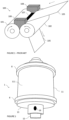
- FIG. 1 An example of roll coating is given in figure 1 , illustrating roll coating of a substrate 105 moving between two rollers 101, 102.
- One roller is the application roller 101 spreading the coating composition onto the substrate 105.
- the second roll is called a support roller 102 and controls the speed of the substrate.
- the coating composition is applied by the application roller 101 to the substrate 105 passing through the nip between two rollers.
- the application roll transfers the coating composition at a given rotating speed. Consequently, the coating composition is subjected to many forces and tends to drift along the circumference of the application roll, to spill and therefore to soil the equipment. Coating spillage or overflow may appear due to considerable compression forces at the nip or due to the rotation of the application roll i.e., from leakage aside from the nip and sprinkles from the coating meniscus formed around the application roller. Therefore, it is necessary to constrain the coating composition within a defined area to avoid smearing the coating equipment with wasted coating composition.
- the coating composition is applied upstream of the coating zone where the substrate passes in between two rollers.
- coating machines 100 are known, as illustrated in figure 1 , to use fixed solid walls 108 on both sides of the dynamic coating pool 107 located on the substrate, in the vicinity of the coating zone, upstream of the nip formed by the two rolls 101, 102.
- the solid walls 108 comprise a V-shaped block wherein the faces of the block fit the cylindrical outer surface of the rollers 101, 102. The block shapes fit the pair of rolls and rises over the level of the coating composition inside the dynamic coating pool 107.
- US2004129156 illustrates a first example of a roll coater using flexographic ink roller with sealing walls at the longitudinal end of the rollers to maintain the coating composition between the two rollers.
- a first limitation of this solution is that the length of the dynamic coating pool must be higher than or equal to the width of the substrate to prevent its deterioration. Therefore, the whole width of the substrate is coated and there is a risk for the coating composition to spread over the lateral extremities of the substrate. Contamination of the equipment may occur, and the substrate's edges could also be worn out or torn apart due to abrasion.
- a second limitation of this solution is that, because the sealing walls are static and the rollers are dynamics in rotation, a friction arises between the rollers and the sealing walls. This friction damages the rollers and/or the sealing walls and their durability is reduced, causing more maintenance to prevent the leak of the coating composition.
- US2887050 illustrates a second example of a roll coating using flexographic ink roller with sealing walls comprising a V-shape block having faces contoured in conformity with the surface of the rolls. Limitations of this solution arise because the sealing walls are attached to the rollers as independent and removable parts.
- a space between the sealing walls and the roll induces a gap whereby the coating composition could flow and whereby friction with rolls could also be induced.
- the coating set-up using ancillary parts is not optimal as they do not efficiently prevent coating composition from flowing out of the coating area in the long run.
- the invention relates to a roller assembly intended to be used in a coating module.
- Said roller assembly comprises a main roller and at least one stopper.
- the main roller includes a central portion intended to receive a coating composition on its outer surface, said central portion being defined by a first lateral side and a second lateral side.
- the at least one stopper is arranged adjacent to the first lateral side or adjacent to the second lateral side of the central portion. Said at least one stopper is designed to prevent migration of the coating composition from the central portion.
- the stopper contains the lateral migration of the coating composition during coating.
- the at least one stopper is designed in such a way that the stress to compress said stopper according to a radial direction of the main roller when it levels with the outer surface of the central portion, is superior to the stress to compress the central portion according to said radial direction.
- the coating composition is advantageously contained within the central portion by a difference of pressure exerted on the coating composition.
- the roller assembly further comprises an inner rigid core.
- the central portion comprises an outer elastic layer covering said inner rigid core.
- the stopper comprises an elastic outer band.
- the stopper comprises at least one side roller arranged adjacent to the first lateral side of the central portion and being free in rotation.
- the outer elastic band, at rest, radially protrudes from the outer surface of the central portion at rest.
- At least a portion of the top outer surface of said outer elastic band comprises a slope going towards the central portion of the main roller.
- the stopper comprises at least one ridge protruding out of the circumferential surface of the rigid core.
- the roller assembly further comprises an outer elastic layer comprising at least a first portion arranged to cover the circumferential surface of the rigid core and a second portion comprising the outer elastic band arranged to cover the at least one ridge.
- the hardness of the at least one ridge is superior to the hardness of the outer elastic band.
- the at least one lateral ridge is embedded between the rigid core and the outer layer or wherein the at least one lateral ridge is designed to level with or protrude from the outer surface of an elastic layer covering the central portion.
- the lateral ridges shaped like a ring or like a thread.
- the at least one stopper is designed to level with the outer surface of the central portion when compressed. In one embodiment, when the elastic outer band levels with the outer surface of the central portion, the stress to compress said stopper according to a radial direction of the main roller, is superior to the stress to compress the central portion according to said radial direction.
- the invention relates to a coating module.
- the coating module comprises:
- the application roller being arranged to coat the substrate supported by the support roller with a coating composition.
- the outer surfaces of both the support roller and the application roller are designed to prevent migration of the coating composition from the central portion.
- the application roller is a roller assembly according to the present invention.
- the support roller is a roller assembly according to the present invention.
- the outer surfaces of both the application roller and the support roller are designed in such a way that, the stress applied to the coating composition between the application roller and the support roller, is higher on the lateral portions than on the central portion to contain the coating composition within the central portion.
- the invention relates to a thermal transfer printing apparatus, comprising a coating module according to the invention to coat the substrate on a coating zone.
- the substrate is an endless ribbon.
- the thermal transfer printing apparatus further comprises a printhead and a conveyor system being designed to hold and transport the endless ribbon from the coating zone to the printhead and from the printhead to the coating zone.
- the invention relates to a method to coat a substrate with a coating composition comprising:
- the invention relates to a roller assembly 1 for a coating module 10.
- Said roller assembly 1 comprises a main roller 11.
- the main roller 11 comprises a central portion 111.
- the main roller 11 is free in rotation around its longitudinal axis B.
- the main roller is an application roller and is intended to apply a coating composition over the substrate 5 supported by a support roller 2 of the coating module 10.
- the main roller is the support roller of the coating module and is intended to transport the substrate and is arranged to press said substrate over the application roller.
- the roller assembly 1 further comprises at least one stopper 8 to contain a coating composition within a central portion 111. Stoppers aim at preventing coating spillage from the rollers upstream the nip or around the roller's circumference (coating meniscus). The stoppers are preferably free in rotation around the longitudinal axis B of the main roller and will be described hereafter.
- the roller assembly comprises at least one stopper 8 on each lateral side of the main roller.
- the central portion 111 is defined between said two stoppers.
- the stoppers are preferably arranged adjacent to the central portion.
- lateral side it should be understood the limits of the central portion according to a direction parallel or sensibly parallel to the longitudinal axis B of the main roller.
- the lateral side comprises the junction between the central portion and one stopper.
- the stopper is in direct contact with the central portion of the roller or with the lateral side of the central portion (i.e., according to the longitudinal axis B).
- the support roller 2 may be a drive roller.
- the coating module 10 comprises a motor to control the rotation of the support roller 2.
- the motor may be connected to a speed controller.
- the support roller controls the speed and the transport of the substrate 5.
- the roller assembly is arranged in such a way that the central portion 111 of the application roller 11 is in contact with a portion of the substrate supported by the support roller.
- the rotation of the application roller 11 around the longitudinal axis B is driven by the rotation of the support roller 2.
- a motor is provided to control the rotation of the application roller 11.
- the coating module 10 further comprises a device 19 to feed the roller assembly 1.
- a device 19 may apply the coating composition directly onto the outer surface of the central portion 111 of the application roller 11 or directly to the ribbon 5 on the side where the ribbon enters the coating system.
- outer is used with respect to the rotation axis of a roller to refer to an element or a surface facing away the rotation axis.
- the outer surface of a roller can be understood as the circumferential surface of said roller.
- the "width" of an element should be understood as its dimension according to a direction parallel to the rotation axis of the main roller or the application roller.
- the nip between the application roller 11 and the substrate 5 supported by the support roller 2 is fed by a dynamic coating pool 7 of coating composition.
- the dynamic coating pool 7 may be an excess of coating composition at the nip between the application roller 11 and the substrate 5 supported by the support roller 2.
- Creating such dynamic coating pool 7 to feed the nip advantageously improves the quality of coating. Indeed, it creates a buffer volume of coating composition, allowing the compensation of height fluctuation and volume variations of the coating composition feeding the coating zone A.
- the coater When the level of the dynamic coating pool is low, the coater is said to be 'ultra-starved'.
- the control of starvation in roll coating system is advantageously improved by the coating module according to the invention. Reducing the supply of liquid leads to the disappearance of the upstream bank giving rise instead to a second inlet meniscus. As a consequence, the level of the dynamic coating pool may rise and lower upon the delivery of the coating composition and determines the appearance of a secondary inlet meniscus onto the application roll.
- the thickness of the coated layer on the substrate preferably ranges from 3 to 100 ⁇ m and more preferably between 3 ⁇ m and 20 ⁇ m.
- the control of the thickness of the coated layer obtained this way may be advantageously homogeneous due to the control of the level of coating composition within the dynamic coating pool 7.
- the application roll is coated with the coating composition.
- the coating composition is limited laterally by the stoppers 8 of the roller assembly to advantageously cope with spillage or splattering and to control nip starvation.
- the width of the substrate 5 is superior to the width of the central portion 111 (i.e., the distance between the two stoppers).
- the substrate 5 and the support roller 2 are arranged in such a way that the substrate 5 covers the entire width of the central portion 111 and extends over both sides of the stoppers.
- One advantage is to maintain the substrate with the stoppers to create a tension on the width of the substrate, allowing the stretch of the substrate and avoiding the fold of the substrate on the coating zone.
- a second advantage is to form uncoated edges of width to delineate the coated layer of the substrate.
- the width of the substrate is equal or lower than the distance between the two stoppers.
- the whole width of the substrate is in contact with the central portion of the main roller and is coated with coating composition.
- the coating module 10 comprises a pressure controller comprising an active element to squeeze the coating composition applied to the substrate 5 between the central portion 111 of the application roller 11 and the support roller 2 along the coating zone.
- the active element may modify the pressure applied between the application roller 11 and the substrate 5 or the along the coating zone A.
- the application roller 11 may be mounted in translation along a linear slide and the pressure controller is configured to control the position of the application roller 11 along said linear slide.
- the position of the application roller 11 directly drives the pressure applied to the coating composition between the two rollers 11, 2.
- the position of the application roller 11 may be controlled with a motor or with a spring-loaded element, or other means known by the skilled person to perform this function.
- the control of the position of the application roller 11 allows the adjustment of the force applied to the application roller 11 against the support roller 2. In one example, reducing the distance between the axis of rotation of the application roller 11 and the axis of rotation of the support roller 2 increases the force applied against the application roller 11.
- the active element comprises magnetic means to apply a force to the application roller 11 in the direction of the support roller 2.
- the pressure controller and the active element control a force applied to the support roller 2 in the direction of the application roller 11.
- the application roller 11 and the support roller 2 have their respective axis of symmetry and rotate around this axis. Both the application roller 11, and the support roller 2 are intended to be mounted onto a frame and to rotate on themselves around their axis of symmetry.
- the rollers 11, 2 have a shape of a cylinder and more preferably a shape of a circular right cylinder.
- at least one roller has a shape of an elliptic cylinder or any shape allowing the transport of a substrate by the rotation of said roller. Stoppers, in particular side rollers, may as well exhibit the shape of a circular right cylinder, an elliptic cylinder or any shape adapted to cooperate with the main or complementary roller.
- One advantage is to control the coating width as to coat a selected portion of the substrate 5. Another advantage is to confine the coating composition within the substrate width and therefore, the risk that the coating composition spills over or underneath the substrate 5 is reduced.
- the stoppers may roll over the substrate: the substrate width is therefore larger than the coating area and the stoppers act as a barrier to coat strips, narrow bands or any width-delimited area over the substrate, for instance.
- a larger substrate than the coating area is also promoting the action of protection provided by the roller's assembly, limiting the risk of spilling, soiling, grime, clogging and dirtying the back side of the substrate.
- the actual coated width is controlled and optimized as to cover the maximum substrate width to coat or defined regions. This enhances the overall process yield as well as limiting waste.
- the raw material resources such as the coating composition and the substrate are optimally used thereon.
- this advantage is particularly interesting at high coating speed and/or when the coating composition is to be rejuvenated and/or when the substrate has to be coated several times over an endless ribbon, especially at high coating or printing speeds.
- a roller assembly and a coating module according to a first aspect of the invention is now described in reference to figures 2 to 4D .
- the main roller 11 comprises a core 114 made of a rigid material and an elastic outer layer 12 preferably elastically deformable.
- the outer surface of one or the other roller may be a smooth surface, preferably without depressions.
- the central portion 111 comprises an outer layer 12 covering a rigid core of the main roller.
- the outer layer 12 may comprise an elastomer or rubber covering, with a thickness preferably ranging from 1 mm and 8 mm, more preferably between 2 and 5 mm.
- the outer layer 12 may comprise or may be made of elastomers.
- the outer layer is preferably made of or comprises a rubber (natural rubber or synthetic rubber) such as EPDM rubber (for ethylene propylene diene monomer rubber).
- EPDM rubber for ethylene propylene diene monomer rubber
- the outer layer is made of or comprises HNBR (for hydrogenated nitrile butadiene rubber).
- HNBR hydrogenated nitrile butadiene rubber
- the hardness of the outer layer 12 preferably ranges from 30 to 90 shore A.
- the coating module may comprise at least a pair of rollers and the hardness of the outer surface of one roller is preferably superior to the hardness of the outer surface of the other.
- a textured surface may comprise regularly arranged depressions designed to transport a coating composition thereon.
- depressions are made in the form of cups made by etching, for example by laser etching. The depth of this depression is a few microns, ranging from about 8 to 25 ⁇ m.
- the roller assembly 1 may comprise an axle 15.
- the application roller 11 is mounted around said axle.
- the application roller 11 and the axle 15 are mechanically connected by fixing means.
- Fixing means may comprise a through hole 17 within the application roller to connect the application roller 11 to the axle with a screw, a pin or any other fixing element.
- axle 15 and the application roller 11 are one unique monobloc element.
- the width of the substrate 5 is superior to the width of the central portion 111 (i.e., the distance between the two stoppers).
- the substrate 5 and the support roller 2 are arranged in such a way that the substrate 5 extends along the entire width of the central portion 111 and beyond the stoppers.
- the uncoated coating composition remains within the coating area and does not leak over the rollers' edges because of the stoppers. This advantageously allows coating a selected portion of the substrate 5 on a predefined width while ensuring cleanliness of the roller assembly.
- nip it should be understood the virtual line wherein the coating composition is pressed between the main roller and the complementary roller, i.e., the contact line of the rollers on the planed defined by the two rollers longitudinal axes.
- coating area it should be understood the surface wherein the coating composition is pressed between the application roller and the support roller.
- each stopper 8 comprises a side roller.
- the central portion 111 is arranged between two sides rollers.
- the side rollers define the boundaries of the central portion 111 of the application roller 11.
- the side rollers are preferably adjacent to the central portion 111 of the main roller 11 and protruding above the outer surface of the central portion 111.
- the side rollers may comprise a plain cylinder or a hollow cylinder.
- the side rollers may comprise two disks mounted in rotation around the longitudinal axis of the main roller.
- the axis of rotation of the side rollers may be the same as the axis of rotation B of the main roller.
- the side rollers may rotate independently from the main roller 11.
- the rotation of the complementary roller 2 will drag the side rollers and will determine the rotation speed of the side rollers, as well as the speed of the substrate.
- the side rollers are designed to radially protrude above the outer surface of the central portion 111 of the main roller 11.
- One advantage is to provide a lateral wall to prevent the coating composition from spreading outside the central portion 111 and to avoid scattering coating droplets over the whole roller assembly.
- the wall may be considered as a dike, i.e. a raised rib-like element.
- each roller comprises an outer elastic band 82 (also called “the elastic band” in the present specification) made of elastic material at the radial extremity of the side roller.
- the elastic band 82 preferably extends from below the outer surface of the central portion and protrudes above the central portion.
- the inner diameter of the outer elastic band 82 at rest of the side roller is inferior to the outer diameter of the central portion 111 of the main roller 11 and the outer diameter of the elastic band 82 at rest of the side roller is superior to the outer diameter of said central portion 111 of the main roller 11.
- the elastic band 82 of the side roller is further designed to flush, or to level with the outer surface 112 of the central portion 111 during coating when compressed.
- the circumferential surface of the elastic band 82 of the side roller 8 is designed to be squashed and flatten by pressure against the outer surface of the complementary roller or the substrate during coating.
- the elastic bands 82 of the side rollers 8 are compressed in such a way that they are constrained to reduce in volume.
- the outer surface of the elastic band aligns with the outer surface of the central portion 111 or with the coating composition layer on said outer surface.
- the top outer surface of the stopper e.g., the elastic band 82 of the side roller or the top outer surface of the side roller
- the junction of the top outer surface of the stopper and the outer surface of the central portion is regular and does not comprise a step nor a gap.
- the outer elastic band locally merges or blends in with the surface of the complementary roller or with the substrate supported by the complementary roller or with the interface between the ink and the substrate.
- the side roller is said to be flush, it means it acts as a sealing wall to contain the coating composition within the coating area.
- the distance between the outer surface of the stopper and the longitudinal axis B is equal or sensibly equal to the distance between the outer surface 112 of the central portion and the longitudinal axis B, for example on each part of the junction between the central portion and the stopper.
- the distance between the outer surface of the side roller and the longitudinal axis B is equal or sensibly equal to the distance between the outer surface 112 of the central portion plus the coating layer thickness and the longitudinal axis B.
- the main roller is the application roller
- the complementary roller is a support roller.
- the application roller comprises an elastomeric cover or sleeve prone to apply a coating composition to the coating zone A with a predefined pressure.
- the pressure controller of the coating module may be configured to compensate the pressure needed to press the outer elastic bands 82 until it flattens against the substrate.
- the elastic band 82 is designed in such a way that the stress to be applied to compress the elastic band 82 from the position at rest to the compressed position wherein the elastic bands 82 is flush with the outer surface of the application roller 11 is constant, linear or sensibly linear along the width of the elastic band 82 (i.e., according to the direction of the axis of rotation B.
- the stress to compress should be understood as a stress to be applied to provide a unitary elastic deformation of the elastic band and/ or the elastic deformation of the outer layer of the central portion of the application roller.
- the compression should be understood as the compression provided between the application roller and the support roller, i.e., according to a direction along the axis passing through the center of each roller or parallel to the radial direction Z of the main roller 11.
- the force to be applied to deform an elastic band 82 until it levels (or is flush) with the outer surface of the application roller 11 is recorded in a memory of the controller.
- the pressure controller is configured to receive the data comprising the force value to be applied to deform an elastic band 82 until it levels (or is flush) with the outer surface of the application roller 11. Data may be transmitted from the memory to the controller.
- the elastic material of the outer elastic bands 82 comprises a foam.
- One advantage of the foam is to allow its elastic compression according to a first direction with a limited elastic deformation in a second direction perpendicular to the first direction.
- One advantage is that the friction between the elastic bands 82 and the holding elements 13 and the friction between the elastic band 82 and the application roller 11 are limited during the compression of the side roller 8, improving the sealing between the lateral side of the central portion 111 and the coating zone A.
- the foam encompasses a semi-solid structure.
- the foam may also be replaced by a resilient structure or any material deformable acting as a sealant such as a gel or a fibrous structure.
- the side rollers coupled with the rotation speed of the rollers, advantageously provide the formation within the dynamic coating pool 7 of a dynamic coating bead that narrows on the edges of the central portion 111.
- Such dynamic coating bead advantageously exhibits a reduced volume of coating composition at its edges and further reduces the risk of overflow over the edge of the coater.
- the coating composition 71 is pressed between the substrate 5 and the outer elastic layer 12 of the application roller 11. Said coating composition within the coating zone A is laterally blocked by the side rollers 8.
- the pressure applied between the substrate 5 and the central portion 111 of the main roller causes the coating to be applied to the substrate in a thin layer.
- the elastic band 82 is designed in such a way that, when squeezed by the support roller 2, its outer surface flushes with the outer surface of the central portion or with the coating composition pressed between the substrate 5 and the central portion 111.
- One advantage of such side rollers 8 is to prevent the coating composition from escaping out of the lateral sides of the central portion 111 and to bring back the coating composition along the coating zone.
- the outer elastic band 82 comprises a first slant profile or have a conical section with a smaller outer diameter on the side of the central portion.
- the top outer surface of the outer elastic band 82 is not flat but comprises a first slope 81 going down toward the central portion 111 of the main roller 11.
- At least one portion of the first slope 81 of the top outer surface of the outer elastic band 82 forms an angle comprised between 20° and 40° with the outer surface of the central portion 111.
- This first slope advantageously provides a better migration of the coating composition to the central portion 111.
- the side rollers comprise an arrow or triangular profile to stretch the ribbon and avoid wrinkles in the ribbon.
- the outer surface of the outer elastic band 82 exhibits a second slope 83 going up toward the central portion 111.
- the first slope 81 is arranged between the second slope 83 and the central portion 111.
- At least one portion of the second slope 83 of the top outer surface of the stopper 8 forms an angle comprised between 20° and 40° with the longitudinal axis B of the main roller. This second slope advantageously reduces the formation of wrinkles in the substrate 5.
- the first slope 81 and the second slope 83 define an angled profile such as an arrow pointing outwards its axis of rotation.
- the angled profile may be symmetrical or preferably asymmetrical.
- An asymmetrical angle advantageously allows to avoid the appearance of wrinkles on the substrate.
- the outer elastic band 82 comprises an asymmetric angled profile to stretch the ribbon.
- One advantage is to avoid wrinkles in the substrate 5.
- the elastic band 82 has a shape of an annular ring. Different shapes of the elastic band can be implemented. Preferably, the shape of the elastic band advantageously allows a homogeneous pressure or a pressure higher on the outside than on the inside (adjacent to the central portion) to guide the liquid composition to the central portion 111.
- the roller assembly comprises at least one holding elements 13.
- the holding elements 13 are arranged to shift each side roller 8 out of the rollers' edges.
- the holding element 13 may comprise a plate mechanically connected to the axle 15 and/or mechanically connected to a lateral portion of the main roller 11.
- the side roller 8 may be fixed along the axial direction between the plate and the central portion 111 of the application roller 11.
- the holding elements 13 comprise an aperture 16 to be fixed with the lateral portion of the application roller 11.
- the rotation of the side roller around the longitudinal axis B of the application roller is independent from the rotation of the application roller.
- both side rollers are mechanically connected to the application roller 11 with a pivot link according to the longitudinal axis B of the application roller 11.
- this pivot link allows the side roller to rotate at an angular speed different than the angular speed of the application roller 11 and the rotation of the support roller drives the rotation of the side rollers.
- This link advantageously reduces friction between the top outer surface of the side rollers and the substrate 5 driven by the support roller 2, as they rotate with the same angular speed.
- the roller assembly 1 comprises bearing 18 to provide such pivot link.
- pivot link it should preferably be understood a mechanical link comprising one unique degree of freedom in rotation and 0 degree of freedom in translation.
- the side rollers and the main roller 11 are mechanically connected by the bearing 18.
- the bearings 18 comprise a rolling-element bearing.
- the rolling-element bearing advantageously comprises rolling elements such as balls or rollers between two concentric grooves rings. The relative motion of said grooves rings causes the rolling elements to roll with limited resistance.
- the bearings comprise at least one solid self-lubricating cylindrical bearing.
- the holding elements 13 is arranged in such a way that the elastic band 82 is squeezed between the central portion of the main roller and the holding element to advantageously provide a hermetic junction between the side roller 8 and the main roller 11. This advantageously prevent the coating composition from penetrating the bearings 18 between the side roller and the main roller 11.
- the longitudinal axis B of the main roller 11 is parallel or sensibly parallel to the axis of rotation of the side roller.
- the rotation axis C of each side roller 80 is parallel or sensibly parallel to the rotation B of the main roller 11.
- the rotation axis C is closer to the outer surface of the main roller than the longitudinal axis B of said main roller.
- the side roller 80 is arranged adjacent to the lateral side 113 of the main roller 11.
- One advantage is to reduce the size of the side roller 80.
- Another advantage is to increase the pressure between the elastic band and the complementary roller. This pressure advantageously improves the blocking of coating composition between the two side rollers 80.
- the side rollers may be mechanically connected to an arm support 83 design to maintain the side roller 80 adjacent to the main roller 11.
- the hermetic sealing between the side roller 80 and the main roller is therefore improved.
- the side roller 80 is tilted with respect to the longitudinal axis B of the main roller.
- the rotation axis C1, C2 of the side roller is not parallel nor sensibly parallel to the longitudinal axis B of the main roller 11.
- the angle ⁇ between the rotation axis C1, C2 of the side roller 80 and the longitudinal axis B of the main roller 11 ranges from 0° to 45°. This range advantageously provides a hermetic sealing between the side roller and the main roller. It also provides the advantage of pressing the elastic band against the substrate or the complementary roller until it is flush with the level of the outer surface of the main roller or with the nip or with the layer of liquid coating composition.
- the side roller is arranged in such a way that the elastic band is adjacent and in contact with the lateral side of the main roller to form a hermetic junction.
- the side roller 80 is also arranged in such a way that the elastic band 82 of the side roller 80 protrudes radially from the outer surface 112 of the central portion 111 at rest and is configured to be flush with said outer surface 112 of the central portion when compressed.
- Said tilted side roller advantageously allows creating pressure gradients between the elastic band and the complementary roller. Furthermore, the tilted side rollers advantageously reduce the friction with the main roller. Finally, the speed of the side roller is not affected by the motion of the main roller. Rather, the side rollers are driven in speed by the substrate and the complementary roller, reducing the friction between the side roller and the substrate.
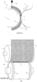
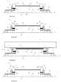
- a roller assembly 30 and a coating module according to a second aspect of the invention is now described in reference to figures 8 to 13 .
- the roller assembly 30 comprises at least one stopper arranged on the main roller adjacent to the central portion 311 of the main roller 31.
- the main roller 31 comprises a rigid core 312 and an outer elastic layer 32.
- the stopper comprises at least one ridge 38 on the outer surface of the core 312 of the main roller 31.
- the roller assembly further comprises an outer elastic layer 32.
- the outer elastic layer 32 comprises at least a portion 321 arranged on the outer surface of the rigid core 312. In sake of clarity, the elastic outer layer 32 is not illustrated in figure 8 and 11 .
- the elastic outer layer 32 may be the same as the outer layer 12 described in the first aspect of the present specification.
- the main roller 31 comprises at least two ridges 38 and said ridges define the lateral side of the central portion 311 of the main roller 31.
- the ridge 38 comprises a step protruding from the core 312 of the main roller.
- the ridge may also comprise an elongated region protruding from the core of the main roller.
- the ridge extends along the surface of the core in such a way it completely radially surrounds the core of the main roller.
- the ridge 38 wraps around the roller for at least one turn.
- the outer surface of the elastic outer layer 32 of the main roller 31 is flat. Indeed, the outer diameter of the main roller 31 covered with its elastic outer layer is the same in the central portion 311 as above the ridges. In other words, the thickness of the elastic outer layer 32 in the central portion 311 is equal or sensibly equal to the sum of the thickness of the ridges plus the thickness of the elastic outer layer in the vicinity of the ridges 38.
- the lateral ridge 38 and the core 312 of the main roller 31 are a unique monobloc piece.
- the lateral ridge 38 is made of a different material from the material of the core of the main roller 31.
- the hardness of the core 312 is superior to the hardness of the material of the lateral ridge 38. More preferably, the hardness of the lateral ridge 38 is inferior to the hardness of the core 312 and superior to the hardness of the outer elastic layer 32.
- the lateral ridge 68 flushes with the outer surface of the outer elastic layer at rest.
- the material of the lateral ridge 68 is chosen in such a way that it provides a pressure high enough to stop the spread of the coating composition out from the central portion 311 but soft enough to avoid damaging the substrate 5.
- the lateral ridge 68 is made of an elastomer such as silicone rubber.
- the outer diameter of the roller assembly on both sides of the junction between a lateral ridge and the central portion 311 is constant.
- the circumferential surface of the roller assembly does not comprise a step between the lateral ridges and the central portion.
- the outer diameter of the roller assembly is constant or sensibly constant in the vicinity of the lateral ridges.
- the radial height of the lateral ridge 58 is superior to the radial height of the elastic outer layer 32.
- the lateral ridge 58 protrudes from the outer surface of the outer elastic layer 32.
- the hardness of the lateral ridge 58 is inferior to the hardness of the outer elastic layer.
- the elastic material of the lateral ridge 58 comprises a foam.
- One advantage of the foam is to allow its compression according to a first direction with a limited elastic deformation in a second direction perpendicular to the first direction.
- the foam encompasses a semi-solid structure.
- the foam may also be replaced by a resilient structure or any material elastically deformable acting as a sealant such as a gel.
- the foam further advantageously allows to damp overall vibrations during coating resulting in a more stabilized process. The quality of coating is therefore improved.
- the height of the ridge is comprised between 10% and 95% of the height of the outer elastic layer within the central portion. This range of thickness advantageously allows to contain the coating composition within the central portion.
- the height of the lateral ridge and the hardness of the outer layer are designed to contain the coating composition within the central portion.
- the ridges provide a pressurized area nearby the ridges, resulting in a higher-pressure profile than in the area of the central portion 311.
- One advantage is to provide a surface of the main roller wherein the stress to compress the outer surface of the central portion 311 is inferior to the stress to compress the main roller above the lateral ridges. In such a way, the coating composition and the substrate 5 squeezed between the main roller and the complementary roller are more compressed on the lateral ridges than on the central portion. This stopper straightforwardly prevents the migration of said coating composition out from the central portion.
- Such pressure profile S is illustrated in figure 10 . Because the elastic outer layer is thicker, the pressure S applied to the coating composition in the central portion 311 is lower than above the ridge. Therefore, the coating composition is restricted from entering the area outside the ridges 38 and converge towards the central portion 311 delimiting the coating zone A. The ridges hinder the coating composition from spreading further aside.
- a stopper comprises one ridge shaped like a ring.
- Each stopper may comprise two ridges shaped like a ring.
- One advantage of the two ridges shaped like a ring in both lateral ends of the central portion 311 is to prevent the spread of coating composition out of the coating zone away from the stoppers.
- a stopper comprises at least one ridge 48 extending helicoidally along the main roller 31.
- the ridge 48 shapes like a thread.
- a thread shape advantageously allows moving back the coating composition towards the central portion 311 more efficiently. Indeed, the coating composition between the two ends of the thread portion will follow the thread profile and come back within the central portion 311.
- This set-up advantageously limits spillage, reduce waste, control the nip starvation, and allows the optimization of the quantity of the coating composition.
- the limit of the central portion depends on the position of the lateral ridges, the width of said central portion within the coating zone A varies slightly during the rotation of the main roller.
- the direction of the thread of a first stopper is the opposite of the direction of a second stopper at the other side of the application roller.
- This advantageously provides a guide to the coating composition to be drawn back to the dynamic coating pool located in the central portion between the onsets first and the second stopper.
- the direction of rotation of the main roller is selected in such a way that the thread-shape profile guides the coating composition to the center portion 311 when rotating against the support roller 2.
- the lateral ridge 48 shaped like a thread, coupled with the rotation speed of the roller assembly, advantageously provide the formation within the dynamic coating pool 7 of a coating bead that narrows on the edges of the central portion 311.
- a coating bead advantageously reduces the risk of overflow and further increase a lower coating thickness on the edge of the coater layer on the substrate.
- Another advantage of the thread shape of the lateral ridges 48 is to improve web handling of the substrate 5 with the stoppers to create a tension on the width of the substrate, allowing the stretch and wrinkle-free continuity of the substrate within the coating zone.
- the invention further relates to a coating module 10 comprising the roller assembly 30 according to the present description.
- the roller assembly 30 comprises only one lateral ridge.
- the coating module is arranged in such a way that the width of the coating zone is arranged vertically. The coating composition within the dynamic coating pool 7 moving down is stopped by the single lateral ridge.
- the roller assembly comprises a heater designed to heat the coating composition.
- the main roller comprises a heater designed to heat its outer surface such as a heating resistor.
- each or at least one stopper further comprises a heater.
- the heater is designed to heat the outer surface of the stopper.
- the heater provides a regulation of temperature to coating composition to the dynamic coating pool and allows keeping the coating composition in a molten state during the coating operation. This also may apply to printing operations, whereby the printing zone should be precisely delimited at the edges.
- the main roller of the roller assembly which comprises the at least one stopper is the application roller of the coating module.
- the at least one stopper may comprise a side roller or at least one ridge protruding out of the inner rigid core of the roller.
- the complementary roller 2 may be a roller assembly as described in the present specification.
- the substrate may be in contact with the top outer surface of the stopper (for instance in the case of side rollers as stoppers) and/or the outer elastic layer covering the top outer surface (for instance in the case of lateral ridges as stoppers). All the features of the stoppers (lateral ridges or the side rollers) described for the application roller are also compatible to be implemented in the support roller and vice versa.
- the coating composition within the nip (or arranged between the two rollers) undergoes a compressive or shear stress which is less pronounced at the central portion of the roller than underneath the stoppers, at the lateral side of this central portion.
- Such pressure profile advantageously prevents the coating composition from moving out of the central portion and leads to coating the substrate with a strip of coating composition with clean edges and further avoids coating composition leaks or spillage on the uncoated side of the substrate.
- both the application roller and the support roller are designed to create such pressure profile (or stress profile) when the coating is performed by pressing the substrate and the coating composition between said application roller and support roller.
- the roller assembly comprises two stoppers, each stopper being adjacent to one lateral side of the central portion.
- the roller assembly comprises a main roller comprising two central portions and comprises a first stopper between these two central portions.
- the first stopper is arranged adjacent to both a first lateral side of a first central portion and to a first lateral side of a second central portion.
- such roller assembly also comprises a second stopper adjacent to the second lateral side of the first central portion and / or a third stopper adjacent to the second lateral side of the second central portion.
- a second stopper adjacent to the second lateral side of the first central portion and / or a third stopper adjacent to the second lateral side of the second central portion.
- the invention relates to a printing apparatus 200 comprising a coating module 10 according to the present invention wherein the substrate 5 is an endless ribbon.
- the printing apparatus 200 further comprises a printhead 204 and a conveyor system 201 to transport the endless ribbon 5 from the coating zone A to the printhead 204 and from the printhead 204 to the coating zone A and so on.
- the printhead comprises a device to a laser beam directed to the endless ribbon to melt the coating composition and to print said melted coating composition on a print support 202.
- roller assembly 30 advantageously prevents dirtying the interior of the printing apparatus. Stoppers advantageously allow keeping the printer clean and running a longer time with no maintenance. Fouling due to the presence of a dynamic coating pool 7 is therefore significantly reduced as to advantageously accelerate the print output.
- the printing apparatus 200 may further comprise a print support 202 to be printed and a printing conveyor system 203 arranged to drive the print support 202 in contact with the endless ribbon 5 along a printing zone to allow the transfer of the coated layer from the endless ribbon to the print support 202.
- the conveyor system 201 is designed to transport the endless ribbon 5 from the coating zone to the print support 202 to perform printing.
- the printhead 204 is arranged to heat the coating composition coated on the endless ribbon on a zone wherein the endless ribbon 5 is in contact with the print support.
- the invention relates to a method for coating a substrate. This method is preferably implemented using the roller assembly and/or the coating module according to the invention.
- the central portion of the main roller of the roller assembly is arranged in contact with the substrate supported by the support roller 2 on its circumferential surface to the ribbon.
- the top outer surfaces of both side rollers are also in contact with the substrate supported by the complementary roller.
- a coating composition is also delivered on the outer surface of the main roller.
- the substrate is transported between the main roller and the complementary roller, preferably covering both the central portion and the at least one stopper.
- the substrate and/or the coating composition are squeezed between the main roller and the complementary roller, preferably on an area comprising both the central portion and the stopper.
- the at least one stopper advantageously limits the lateral spreading of the liquid coating composition on the dynamic coating pool 7 out from the central portion.
- the stress to compress the outer elastic band of the stopper is superior to the stress to compress the outer layer of the central portion, leading to prevent the lateral migration of the coating composition from the central portion.
- the invention relates to a method to print a coating composition on a print support using a thermal transfer printing apparatus.
- the coating module 10 When the coating module 10 is comprised in a thermal transfer printing apparatus, the portion of the endless ribbon 5 (i.e., the substrate) exiting the coating zone A and coated is conveyed by the conveyor system to the printhead for printing. During printing, a portion of the coating composition is thermally transferred to the print support 202 and the remaining coating composition un-transferred remains on the ribbon 5.
- the remaining coating composition which has not been printed is then transported by the ribbon 5 to the coating zone A to be coated again, providing ink-rejuvenation. This remaining coating composition is then used to fill the dynamic coating pool 7 of the coating module.
- Said coating composition to be rejuvenated (especially a portion at the border of the coating strip), when melted in contact with the heated application roller, is centered or moved to back the central portion thanks to the stoppers arranged adjacent to the lateral side of the central portion. Therefore, the invention enables a strip of coating composition to be coated onto the substrate with clean edges.
- the remaining coating composition on the ribbon 5 is heated between the printhead 204 and the coating zone A, preferably above its melting point.
- the heating of the remaining ink coating composition advantageously melts the coating composition before arriving on the dynamic coating pool 7.
- One advantage of the present invention is to handle the thickness of the layer of ink coated 124 on the ribbon, independently of the quantity of remaining ink 132 on the ribbon arriving on the coating zone A.
Landscapes
- Coating Apparatus (AREA)
Priority Applications (2)
| Application Number | Priority Date | Filing Date | Title |
|---|---|---|---|
| EP23315278.4A EP4491400A1 (fr) | 2023-07-11 | 2023-07-11 | Ensemble rouleau comprenant des bouchons |
| PCT/EP2024/069475 WO2025012312A1 (fr) | 2023-07-11 | 2024-07-10 | Ensemble rouleau comprenant des butées |
Applications Claiming Priority (1)
| Application Number | Priority Date | Filing Date | Title |
|---|---|---|---|
| EP23315278.4A EP4491400A1 (fr) | 2023-07-11 | 2023-07-11 | Ensemble rouleau comprenant des bouchons |
Publications (1)
| Publication Number | Publication Date |
|---|---|
| EP4491400A1 true EP4491400A1 (fr) | 2025-01-15 |
Family
ID=87554553
Family Applications (1)
| Application Number | Title | Priority Date | Filing Date |
|---|---|---|---|
| EP23315278.4A Withdrawn EP4491400A1 (fr) | 2023-07-11 | 2023-07-11 | Ensemble rouleau comprenant des bouchons |
Country Status (2)
| Country | Link |
|---|---|
| EP (1) | EP4491400A1 (fr) |
| WO (1) | WO2025012312A1 (fr) |
Citations (5)
| Publication number | Priority date | Publication date | Assignee | Title |
|---|---|---|---|---|
| US2887050A (en) | 1957-07-11 | 1959-05-19 | Samuel M Langston Co | Flexographic ink fountains |
| US5979314A (en) * | 1994-08-19 | 1999-11-09 | Varn Products Company, Inc. | Lithographic dampener |
| JP2003190856A (ja) * | 2001-12-26 | 2003-07-08 | Toppan Printing Co Ltd | グラビア塗布装置およびグラビア塗布方法 |
| US20040129156A1 (en) | 2002-12-27 | 2004-07-08 | Nokihisa Adachi | Apparatus for removing and/or recovering ink, printing machine including such apparatus, and method for supplying and/or recovering ink |
| JP2012061699A (ja) * | 2010-09-15 | 2012-03-29 | Ricoh Co Ltd | 画像形成装置及び処理液塗布装置 |
-
2023
- 2023-07-11 EP EP23315278.4A patent/EP4491400A1/fr not_active Withdrawn
-
2024
- 2024-07-10 WO PCT/EP2024/069475 patent/WO2025012312A1/fr active Pending
Patent Citations (5)
| Publication number | Priority date | Publication date | Assignee | Title |
|---|---|---|---|---|
| US2887050A (en) | 1957-07-11 | 1959-05-19 | Samuel M Langston Co | Flexographic ink fountains |
| US5979314A (en) * | 1994-08-19 | 1999-11-09 | Varn Products Company, Inc. | Lithographic dampener |
| JP2003190856A (ja) * | 2001-12-26 | 2003-07-08 | Toppan Printing Co Ltd | グラビア塗布装置およびグラビア塗布方法 |
| US20040129156A1 (en) | 2002-12-27 | 2004-07-08 | Nokihisa Adachi | Apparatus for removing and/or recovering ink, printing machine including such apparatus, and method for supplying and/or recovering ink |
| JP2012061699A (ja) * | 2010-09-15 | 2012-03-29 | Ricoh Co Ltd | 画像形成装置及び処理液塗布装置 |
Also Published As
| Publication number | Publication date |
|---|---|
| WO2025012312A1 (fr) | 2025-01-16 |
Similar Documents
| Publication | Publication Date | Title |
|---|---|---|
| US4948635A (en) | Gravure coating device and method | |
| US6736500B2 (en) | Image forming method and apparatus that form and transfer image of liquid drops of increased viscosity | |
| JP6205939B2 (ja) | インクジェットプリンタ用処理剤液塗布装置 | |
| KR20060041789A (ko) | 액체 도포 장치 및 잉크 제트 기록 장치 | |
| EP4259445B1 (fr) | Module de revêtement pour revêtement de ruban à vitesse variable | |
| EP4491400A1 (fr) | Ensemble rouleau comprenant des bouchons | |
| EP3393808B1 (fr) | Appareil pour impression flexographique et module d'entrée | |
| KR19990043985A (ko) | 출력 롤러를 구비한 역전 그라비어 키스 코팅 장치 | |
| US8312834B2 (en) | Apparatus for applying thin coating | |
| US4116162A (en) | Coating device | |
| US4859507A (en) | High speed paper coaters | |
| FI106934B (fi) | Menetelmä liikkuvan rainan päällystämiseksi kaksipuolisesti | |
| EP1481737A1 (fr) | Machine a enduire et procede de production d'une feuille enduite et barre d'aerosustentation a rotation minimale | |
| CA1090119A (fr) | Rouleau pour dispositif d'induction | |
| US20120020708A1 (en) | Oil pressurized foam roll | |
| GB1598236A (en) | Ink metering apparatus | |
| US4538518A (en) | Ink metering apparatus | |
| US5766350A (en) | Applicator system for a web-coating apparatus | |
| JPS63137766A (ja) | 転写装置 | |
| JPH0647586Y2 (ja) | 塗工装置 | |
| JP2555268B2 (ja) | 輪転印刷機械 | |
| US5680815A (en) | Dampening unit for an offset printing machine | |
| US4798138A (en) | Liquid distribution system | |
| US6379462B1 (en) | Metering system for an apparatus for coating webs of material such as paper, paperboard or cardboard webs | |
| US5404818A (en) | Inking system for printing ink rollers |
Legal Events
| Date | Code | Title | Description |
|---|---|---|---|
| PUAI | Public reference made under article 153(3) epc to a published international application that has entered the european phase |
Free format text: ORIGINAL CODE: 0009012 |
|
| STAA | Information on the status of an ep patent application or granted ep patent |
Free format text: STATUS: THE APPLICATION HAS BEEN PUBLISHED |
|
| AK | Designated contracting states |
Kind code of ref document: A1 Designated state(s): AL AT BE BG CH CY CZ DE DK EE ES FI FR GB GR HR HU IE IS IT LI LT LU LV MC ME MK MT NL NO PL PT RO RS SE SI SK SM TR |
|
| STAA | Information on the status of an ep patent application or granted ep patent |
Free format text: STATUS: THE APPLICATION IS DEEMED TO BE WITHDRAWN |
|
| 18D | Application deemed to be withdrawn |
Effective date: 20250716 |