EP4491444A1 - Systèmes et procédés de commande d'une mise sous échange de bloc-batterie pour un aéronef - Google Patents
Systèmes et procédés de commande d'une mise sous échange de bloc-batterie pour un aéronef Download PDFInfo
- Publication number
- EP4491444A1 EP4491444A1 EP24187243.1A EP24187243A EP4491444A1 EP 4491444 A1 EP4491444 A1 EP 4491444A1 EP 24187243 A EP24187243 A EP 24187243A EP 4491444 A1 EP4491444 A1 EP 4491444A1
- Authority
- EP
- European Patent Office
- Prior art keywords
- battery
- battery pack
- aircraft
- assembly
- rail
- Prior art date
- Legal status (The legal status is an assumption and is not a legal conclusion. Google has not performed a legal analysis and makes no representation as to the accuracy of the status listed.)
- Pending
Links
Images



Classifications
-
- B—PERFORMING OPERATIONS; TRANSPORTING
- B60—VEHICLES IN GENERAL
- B60L—PROPULSION OF ELECTRICALLY-PROPELLED VEHICLES; SUPPLYING ELECTRIC POWER FOR AUXILIARY EQUIPMENT OF ELECTRICALLY-PROPELLED VEHICLES; ELECTRODYNAMIC BRAKE SYSTEMS FOR VEHICLES IN GENERAL; MAGNETIC SUSPENSION OR LEVITATION FOR VEHICLES; MONITORING OPERATING VARIABLES OF ELECTRICALLY-PROPELLED VEHICLES; ELECTRIC SAFETY DEVICES FOR ELECTRICALLY-PROPELLED VEHICLES
- B60L53/00—Methods of charging batteries, specially adapted for electric vehicles; Charging stations or on-board charging equipment therefor; Exchange of energy storage elements in electric vehicles
- B60L53/80—Exchanging energy storage elements, e.g. removable batteries
-
- B—PERFORMING OPERATIONS; TRANSPORTING
- B60—VEHICLES IN GENERAL
- B60L—PROPULSION OF ELECTRICALLY-PROPELLED VEHICLES; SUPPLYING ELECTRIC POWER FOR AUXILIARY EQUIPMENT OF ELECTRICALLY-PROPELLED VEHICLES; ELECTRODYNAMIC BRAKE SYSTEMS FOR VEHICLES IN GENERAL; MAGNETIC SUSPENSION OR LEVITATION FOR VEHICLES; MONITORING OPERATING VARIABLES OF ELECTRICALLY-PROPELLED VEHICLES; ELECTRIC SAFETY DEVICES FOR ELECTRICALLY-PROPELLED VEHICLES
- B60L58/00—Methods or circuit arrangements for monitoring or controlling batteries or fuel cells, specially adapted for electric vehicles
- B60L58/10—Methods or circuit arrangements for monitoring or controlling batteries or fuel cells, specially adapted for electric vehicles for monitoring or controlling batteries
- B60L58/12—Methods or circuit arrangements for monitoring or controlling batteries or fuel cells, specially adapted for electric vehicles for monitoring or controlling batteries responding to state of charge [SoC]
-
- B—PERFORMING OPERATIONS; TRANSPORTING
- B60—VEHICLES IN GENERAL
- B60L—PROPULSION OF ELECTRICALLY-PROPELLED VEHICLES; SUPPLYING ELECTRIC POWER FOR AUXILIARY EQUIPMENT OF ELECTRICALLY-PROPELLED VEHICLES; ELECTRODYNAMIC BRAKE SYSTEMS FOR VEHICLES IN GENERAL; MAGNETIC SUSPENSION OR LEVITATION FOR VEHICLES; MONITORING OPERATING VARIABLES OF ELECTRICALLY-PROPELLED VEHICLES; ELECTRIC SAFETY DEVICES FOR ELECTRICALLY-PROPELLED VEHICLES
- B60L58/00—Methods or circuit arrangements for monitoring or controlling batteries or fuel cells, specially adapted for electric vehicles
- B60L58/10—Methods or circuit arrangements for monitoring or controlling batteries or fuel cells, specially adapted for electric vehicles for monitoring or controlling batteries
- B60L58/18—Methods or circuit arrangements for monitoring or controlling batteries or fuel cells, specially adapted for electric vehicles for monitoring or controlling batteries of two or more battery modules
-
- B—PERFORMING OPERATIONS; TRANSPORTING
- B64—AIRCRAFT; AVIATION; COSMONAUTICS
- B64D—EQUIPMENT FOR FITTING IN OR TO AIRCRAFT; FLIGHT SUITS; PARACHUTES; ARRANGEMENT OR MOUNTING OF POWER PLANTS OR PROPULSION TRANSMISSIONS IN AIRCRAFT
- B64D27/00—Arrangement or mounting of power plants in aircraft; Aircraft characterised by the type or position of power plants
- B64D27/02—Aircraft characterised by the type or position of power plants
- B64D27/30—Aircraft characterised by electric power plants
- B64D27/32—Aircraft characterised by electric power plants within, or attached to, fuselages
-
- B—PERFORMING OPERATIONS; TRANSPORTING
- B64—AIRCRAFT; AVIATION; COSMONAUTICS
- B64D—EQUIPMENT FOR FITTING IN OR TO AIRCRAFT; FLIGHT SUITS; PARACHUTES; ARRANGEMENT OR MOUNTING OF POWER PLANTS OR PROPULSION TRANSMISSIONS IN AIRCRAFT
- B64D27/00—Arrangement or mounting of power plants in aircraft; Aircraft characterised by the type or position of power plants
- B64D27/02—Aircraft characterised by the type or position of power plants
- B64D27/30—Aircraft characterised by electric power plants
- B64D27/35—Arrangements for on-board electric energy production, distribution, recovery or storage
- B64D27/357—Arrangements for on-board electric energy production, distribution, recovery or storage using batteries
-
- B—PERFORMING OPERATIONS; TRANSPORTING
- B64—AIRCRAFT; AVIATION; COSMONAUTICS
- B64F—GROUND OR AIRCRAFT-CARRIER-DECK INSTALLATIONS SPECIALLY ADAPTED FOR USE IN CONNECTION WITH AIRCRAFT; DESIGNING, MANUFACTURING, ASSEMBLING, CLEANING, MAINTAINING OR REPAIRING AIRCRAFT, NOT OTHERWISE PROVIDED FOR; HANDLING, TRANSPORTING, TESTING OR INSPECTING AIRCRAFT COMPONENTS, NOT OTHERWISE PROVIDED FOR
- B64F1/00—Ground or aircraft-carrier-deck installations
- B64F1/35—Ground or aircraft-carrier-deck installations for supplying electrical power to stationary aircraft
- B64F1/352—Mobile units
-
- B—PERFORMING OPERATIONS; TRANSPORTING
- B64—AIRCRAFT; AVIATION; COSMONAUTICS
- B64U—UNMANNED AERIAL VEHICLES [UAV]; EQUIPMENT THEREFOR
- B64U50/00—Propulsion; Power supply
- B64U50/30—Supply or distribution of electrical power
- B64U50/39—Battery swapping
-
- H—ELECTRICITY
- H01—ELECTRIC ELEMENTS
- H01M—PROCESSES OR MEANS, e.g. BATTERIES, FOR THE DIRECT CONVERSION OF CHEMICAL ENERGY INTO ELECTRICAL ENERGY
- H01M10/00—Secondary cells; Manufacture thereof
- H01M10/42—Methods or arrangements for servicing or maintenance of secondary cells or secondary half-cells
- H01M10/48—Accumulators combined with arrangements for measuring, testing or indicating the condition of cells, e.g. the level or density of the electrolyte
- H01M10/482—Accumulators combined with arrangements for measuring, testing or indicating the condition of cells, e.g. the level or density of the electrolyte for several batteries or cells simultaneously or sequentially
-
- H—ELECTRICITY
- H01—ELECTRIC ELEMENTS
- H01M—PROCESSES OR MEANS, e.g. BATTERIES, FOR THE DIRECT CONVERSION OF CHEMICAL ENERGY INTO ELECTRICAL ENERGY
- H01M50/00—Constructional details or processes of manufacture of the non-active parts of electrochemical cells other than fuel cells, e.g. hybrid cells
- H01M50/20—Mountings; Secondary casings or frames; Racks, modules or packs; Suspension devices; Shock absorbers; Transport or carrying devices; Holders
-
- H—ELECTRICITY
- H01—ELECTRIC ELEMENTS
- H01M—PROCESSES OR MEANS, e.g. BATTERIES, FOR THE DIRECT CONVERSION OF CHEMICAL ENERGY INTO ELECTRICAL ENERGY
- H01M50/00—Constructional details or processes of manufacture of the non-active parts of electrochemical cells other than fuel cells, e.g. hybrid cells
- H01M50/20—Mountings; Secondary casings or frames; Racks, modules or packs; Suspension devices; Shock absorbers; Transport or carrying devices; Holders
- H01M50/244—Secondary casings; Racks; Suspension devices; Carrying devices; Holders characterised by their mounting method
-
- H—ELECTRICITY
- H01—ELECTRIC ELEMENTS
- H01M—PROCESSES OR MEANS, e.g. BATTERIES, FOR THE DIRECT CONVERSION OF CHEMICAL ENERGY INTO ELECTRICAL ENERGY
- H01M50/00—Constructional details or processes of manufacture of the non-active parts of electrochemical cells other than fuel cells, e.g. hybrid cells
- H01M50/20—Mountings; Secondary casings or frames; Racks, modules or packs; Suspension devices; Shock absorbers; Transport or carrying devices; Holders
- H01M50/249—Mountings; Secondary casings or frames; Racks, modules or packs; Suspension devices; Shock absorbers; Transport or carrying devices; Holders specially adapted for aircraft or vehicles, e.g. cars or trains
-
- H—ELECTRICITY
- H01—ELECTRIC ELEMENTS
- H01M—PROCESSES OR MEANS, e.g. BATTERIES, FOR THE DIRECT CONVERSION OF CHEMICAL ENERGY INTO ELECTRICAL ENERGY
- H01M50/00—Constructional details or processes of manufacture of the non-active parts of electrochemical cells other than fuel cells, e.g. hybrid cells
- H01M50/20—Mountings; Secondary casings or frames; Racks, modules or packs; Suspension devices; Shock absorbers; Transport or carrying devices; Holders
- H01M50/256—Carrying devices, e.g. belts
-
- H—ELECTRICITY
- H01—ELECTRIC ELEMENTS
- H01M—PROCESSES OR MEANS, e.g. BATTERIES, FOR THE DIRECT CONVERSION OF CHEMICAL ENERGY INTO ELECTRICAL ENERGY
- H01M50/00—Constructional details or processes of manufacture of the non-active parts of electrochemical cells other than fuel cells, e.g. hybrid cells
- H01M50/20—Mountings; Secondary casings or frames; Racks, modules or packs; Suspension devices; Shock absorbers; Transport or carrying devices; Holders
- H01M50/289—Mountings; Secondary casings or frames; Racks, modules or packs; Suspension devices; Shock absorbers; Transport or carrying devices; Holders characterised by spacing elements or positioning means within frames, racks or packs
- H01M50/291—Mountings; Secondary casings or frames; Racks, modules or packs; Suspension devices; Shock absorbers; Transport or carrying devices; Holders characterised by spacing elements or positioning means within frames, racks or packs characterised by their shape
-
- B—PERFORMING OPERATIONS; TRANSPORTING
- B60—VEHICLES IN GENERAL
- B60L—PROPULSION OF ELECTRICALLY-PROPELLED VEHICLES; SUPPLYING ELECTRIC POWER FOR AUXILIARY EQUIPMENT OF ELECTRICALLY-PROPELLED VEHICLES; ELECTRODYNAMIC BRAKE SYSTEMS FOR VEHICLES IN GENERAL; MAGNETIC SUSPENSION OR LEVITATION FOR VEHICLES; MONITORING OPERATING VARIABLES OF ELECTRICALLY-PROPELLED VEHICLES; ELECTRIC SAFETY DEVICES FOR ELECTRICALLY-PROPELLED VEHICLES
- B60L2200/00—Type of vehicles
- B60L2200/10—Air crafts
-
- B—PERFORMING OPERATIONS; TRANSPORTING
- B60—VEHICLES IN GENERAL
- B60L—PROPULSION OF ELECTRICALLY-PROPELLED VEHICLES; SUPPLYING ELECTRIC POWER FOR AUXILIARY EQUIPMENT OF ELECTRICALLY-PROPELLED VEHICLES; ELECTRODYNAMIC BRAKE SYSTEMS FOR VEHICLES IN GENERAL; MAGNETIC SUSPENSION OR LEVITATION FOR VEHICLES; MONITORING OPERATING VARIABLES OF ELECTRICALLY-PROPELLED VEHICLES; ELECTRIC SAFETY DEVICES FOR ELECTRICALLY-PROPELLED VEHICLES
- B60L2240/00—Control parameters of input or output; Target parameters
- B60L2240/60—Navigation input
-
- B—PERFORMING OPERATIONS; TRANSPORTING
- B60—VEHICLES IN GENERAL
- B60L—PROPULSION OF ELECTRICALLY-PROPELLED VEHICLES; SUPPLYING ELECTRIC POWER FOR AUXILIARY EQUIPMENT OF ELECTRICALLY-PROPELLED VEHICLES; ELECTRODYNAMIC BRAKE SYSTEMS FOR VEHICLES IN GENERAL; MAGNETIC SUSPENSION OR LEVITATION FOR VEHICLES; MONITORING OPERATING VARIABLES OF ELECTRICALLY-PROPELLED VEHICLES; ELECTRIC SAFETY DEVICES FOR ELECTRICALLY-PROPELLED VEHICLES
- B60L2260/00—Operating Modes
- B60L2260/40—Control modes
- B60L2260/50—Control modes by future state prediction
- B60L2260/54—Energy consumption estimation
-
- B—PERFORMING OPERATIONS; TRANSPORTING
- B64—AIRCRAFT; AVIATION; COSMONAUTICS
- B64C—AEROPLANES; HELICOPTERS
- B64C27/00—Rotorcraft; Rotors peculiar thereto
- B64C27/04—Helicopters
- B64C27/06—Helicopters with single rotor
-
- B—PERFORMING OPERATIONS; TRANSPORTING
- B64—AIRCRAFT; AVIATION; COSMONAUTICS
- B64D—EQUIPMENT FOR FITTING IN OR TO AIRCRAFT; FLIGHT SUITS; PARACHUTES; ARRANGEMENT OR MOUNTING OF POWER PLANTS OR PROPULSION TRANSMISSIONS IN AIRCRAFT
- B64D27/00—Arrangement or mounting of power plants in aircraft; Aircraft characterised by the type or position of power plants
- B64D27/02—Aircraft characterised by the type or position of power plants
- B64D27/30—Aircraft characterised by electric power plants
- B64D27/33—Hybrid electric aircraft
-
- B—PERFORMING OPERATIONS; TRANSPORTING
- B64—AIRCRAFT; AVIATION; COSMONAUTICS
- B64D—EQUIPMENT FOR FITTING IN OR TO AIRCRAFT; FLIGHT SUITS; PARACHUTES; ARRANGEMENT OR MOUNTING OF POWER PLANTS OR PROPULSION TRANSMISSIONS IN AIRCRAFT
- B64D27/00—Arrangement or mounting of power plants in aircraft; Aircraft characterised by the type or position of power plants
- B64D27/02—Aircraft characterised by the type or position of power plants
- B64D27/30—Aircraft characterised by electric power plants
- B64D27/34—All-electric aircraft
-
- H—ELECTRICITY
- H01—ELECTRIC ELEMENTS
- H01M—PROCESSES OR MEANS, e.g. BATTERIES, FOR THE DIRECT CONVERSION OF CHEMICAL ENERGY INTO ELECTRICAL ENERGY
- H01M2220/00—Batteries for particular applications
- H01M2220/20—Batteries in motive systems, e.g. vehicle, ship, plane
Definitions
- This disclosure relates generally to battery assemblies for aircraft and aircraft propulsion systems and, more particularly, to systems and methods for controlling a battery pack loadout for an aircraft.
- Propulsion systems for aircraft may include an electrical distribution system including one or more battery packs and an electric motor. Before conducting a flight operation with the aircraft, a particular charge level of the one or more battery packs may be obtained.
- Various systems and methods for controlling a charge level of battery packs for aircraft are known in the art. While these known systems and methods have various advantages, there is still room in the art for improvement.
- a battery replacement system for controlling a battery pack loadout for an aircraft having at least one installed battery pack includes a vehicle including a battery storage assembly, a controller, and a battery transfer assembly.
- the battery storage assembly is configured for storing at least one stored battery pack.
- the controller includes a processor in communication with a non-transitory memory storing instructions, which instructions when executed by the processor, cause the processor to identify a state of charge for each of the at least one installed battery pack installed on the aircraft, identify an energy storage prerequisite for a flight or series of flights of the aircraft using flight information for the aircraft, and identify a battery pack loadout plan for the aircraft using the energy storage prerequisite and the state of charge for each of the at least one installed battery pack.
- the battery pack loadout plan identifies one or more of the at least one stored battery pack to be installed on the aircraft.
- the instructions when executed by the processor, further cause the processor to control the battery pack loadout for the aircraft by controlling the battery transfer assembly to install the one or more of the at least one stored battery pack into the aircraft.
- the battery pack loadout plan may further identify at least one installed battery pack installed on the aircraft to be removed from the aircraft.
- the instructions when executed by the processor, may further cause the processor to identify a lowest state of charge installed battery pack of the at least one installed battery pack.
- the instructions when executed by the processor, may further cause the processor to control the battery pack loadout for the aircraft by controlling the battery transfer assembly to receive the lowest state of charge battery pack from the aircraft and move the lowest state of charge battery pack to the battery storage assembly.
- the flight information may include one or more of a departure location, a landing location, a flight distance for the flight or the series of flights, an aircraft model of the aircraft, a number of passengers for the flight or the series of flights, an aircraft weight of the aircraft, or a weather condition.
- the battery storage assembly may include a plurality of rail assemblies.
- Each rail assembly of the plurality of rail assemblies may include a first rail and a second rail.
- Each stored battery pack of the at least one stored battery pack may be disposed on the first rail and the second rail of a respective one of the plurality of rail assemblies.
- the battery transfer assembly may include a battery transfer tray and an actuator.
- the battery transfer tray may include a transfer rail assembly including a first transfer rail and a second transfer rail.
- the battery transfer tray may be mounted to the actuator.
- the actuator may be configured to selectively position the transfer rail assembly at one of the rail assemblies of the plurality of rail assemblies.
- the battery replacement system may further include the at least one stored battery pack.
- the at least one stored battery pack may include a battery rail assembly including a first battery rail and a second battery rail.
- the instructions when executed by the processor, may further cause the processor to control the battery transfer assembly to install the one or more of the at least one stored battery pack into the aircraft by controlling the battery transfer assembly to receive the one or more of the at least one stored battery pack from the battery storage assembly and install the one or more of the at least one stored battery pack into the aircraft.
- a method for controlling a battery pack loadout for an aircraft having at least one installed battery pack includes identifying, with a controller, a state of charge for each of the at least one installed battery pack installed on the aircraft, receiving flight information for a flight or series of flights of the aircraft with the controller, identifying, with the controller, an energy storage prerequisite for the flight or series of flights of the aircraft using the flight information for the aircraft, and identifying, with the controller, a battery pack loadout plan for the aircraft using the energy storage prerequisite and the state of charge for each of the at least one installed battery pack.
- the battery pack loadout plan identifies a plurality of battery packs for the aircraft.
- the plurality of battery packs have a combined state of charge which is equal to or greater than the energy storage prerequisite.
- the method further includes controlling the battery pack loadout for the aircraft by controlling a vehicle, with the controller, to remove a first battery pack from the aircraft and to install a second battery pack into the aircraft such that the aircraft includes the plurality of battery packs.
- the first battery pack may be the lowest state of charge installed battery pack.
- the flight information may include one or more of a departure location, a landing location, a flight distance for the flight or the series of flights, an aircraft model of the aircraft, a number of passengers for the flight or the series of flights, an aircraft weight of the aircraft, or a weather condition.
- the aircraft may have a battery pack capacity and the battery pack loadout plan may include a quantity of battery packs which is less than the battery pack capacity.
- removing the first battery pack from the aircraft may include removing the first battery pack with a battery transfer assembly of the vehicle, moving the first battery pack from the battery transfer assembly to a battery storage assembly of the vehicle, and storing the first battery pack in the battery storage assembly.
- a battery replacement system for controlling a battery pack loadout for an aircraft having at least one installed battery pack includes a vehicle including a battery storage assembly and a controller.
- the battery storage assembly is configured for storing a plurality of stored battery packs.
- the controller includes a processor in communication with a non-transitory memory storing instructions, which instructions when executed by the processor, cause the processor to identify a state of charge for each of the at least one installed battery pack installed on the aircraft, identify a state of charge for each of the stored battery packs, identify an energy storage prerequisite for a flight or series of flights of the aircraft using flight information for the aircraft, and identify a battery pack loadout plan for the aircraft using the energy storage prerequisite, the identified state of charge for each of the at least one installed battery pack, and the identified state of charge for each of the plurality of stored battery packs.
- the battery pack loadout plan identifies a plurality of battery packs for the aircraft.
- the plurality of battery packs have a combined state of charge which is equal to or greater than the energy storage prerequisite.
- the plurality of battery packs includes at least one battery pack of the plurality of stored battery packs.
- the flight information may include one or more of a departure location, a landing location, a flight distance for the flight or the series of flights, an aircraft model of the aircraft, a number of passengers for the flight or the series of flights, an aircraft weight of the aircraft, or a weather condition.
- the plurality of battery packs may further include one or more of the at least one installed battery pack.
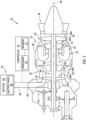
- FIG. 1 illustrates aside, cutaway view of a propulsion system 20 configured for an aircraft.
- the aircraft may be a fixed-wing aircraft (e.g., an airplane), a rotary-wing aircraft (e.g., a helicopter), a tilt-rotor aircraft, a tilt-wing aircraft, or any other aerial vehicle.
- the aircraft may be a manned aerial vehicle or an unmanned aerial vehicle (UAV, e.g., a drone).
- the aircraft propulsion system 20 of FIG. 1 is configured as a hybrid-electric propulsion system including an engine 22.
- the propulsion system 20 and/or the aircraft on which the propulsion system 20 is installed may include a battery assembly 24.
- the propulsion system 20 may further include a controller 26.
- the present disclosure is not limited to aircraft propulsion systems including an engine, and aspects of the present disclosure are equally applicable to fully-electric aircraft propulsion systems.
- the engine 22 of FIG. 1 is configured as a turboshaft gas turbine engine.
- gas turbine engines such as, but not limited to, a turboprop gas turbine engine, a turbofan gas turbine engine, a turbojet gas turbine engine, a propfan gas turbine engine, an open rotor gas turbine engine, an auxiliary power unit (APU), or the like.
- present disclosure is also applicable to other configurations of engines such as, but not limited to, a rotary engine (e.g., a Wankel engine), a diesel internal combustion engine, or the like, which may be used for hybrid-electric, aircraft propulsion systems.
- the engine 22 of FIG. 1 includes an air inlet 28, a compressor section 30, a combustion section 32, a turbine section 34, an exhaust section 36, and an engine static structure 38.
- the air inlet 28, the compressor section 30, the combustion section 32, the turbine section 34, and the exhaust section 36 are arranged along an axial centerline 40 (e.g., a rotational axis) of the engine 22.
- the compressor section 30 may include a low-pressure compressor 30A and a high-pressure compressor 30B.
- the combustion section 32 may include a combustor 42 forming an annular combustion chamber.
- the turbine section 34 may include a high-pressure turbine 34A and a low-pressure turbine 34B (e.g., a power turbine).
- the first rotational assembly 44 includes a first shaft 48, a bladed first compressor rotor 50 for the high-pressure compressor 30B, and a bladed first turbine rotor 52 for the high-pressure turbine 34A.
- the first shaft 48 interconnects the bladed first compressor rotor 50 and the bladed first turbine rotor 52.
- the second rotational assembly 46 includes a second shaft 54, a bladed second compressor rotor 56 for the low-pressure compressor 30A, and a bladed second turbine rotor 58 for the low-pressure turbine 34B.
- the second rotational assembly 46 may further include an electric motor 60.
- the second shaft 54 interconnects the bladed second compressor rotor 56 and the bladed second turbine rotor 58.
- the second shaft 54 is directly or indirectly connected to one or more rotational loads (not shown in FIG. 1 ) such as, but not limited to, a propeller or other propulsor.
- the second shaft 54 may be coupled with the rotational loads by one or more gear assemblies 62.
- the gear assemblies 62 may be configured to drive rotation of the rotational loads at a different (e.g., reduced) rotational speed relative to the second shaft 54.
- the electric motor 60 of FIG. 1 is coupled with the second shaft 54 to drive rotation of the second shaft 54 alone or in combination with the bladed second turbine rotor 58.
- the electric motor 60 may be directly connected to the second shaft 54.
- the electric motor 60 may be indirectly coupled with the second shaft 54, for example, using a clutch or gearbox assembly.
- the present disclosure is not limited to the foregoing exemplary configurations of the electric motor 60.
- the battery assembly 24 of FIG. 1 includes a battery 64 and an electrical distribution bus 66.
- the battery 64 is configured to supply electrical power to one or more electrical loads (e.g., electronic control systems, environmental control systems, electric motors, lighting systems, communication systems, etc.) of the propulsion system 20 and/or its associated aircraft through the electrical distribution bus 66.
- the battery 64 of FIG. 1 is configured to supply electrical power to the electric motor 60 to facilitate operation of the electric motor 60.
- the battery 64 includes a plurality of battery packs 68 (e.g., selectively removable battery modules) disposed in the propulsion system 20 and/or its associated aircraft.
- the battery packs may be electrically connected together in series and/or parallel as necessary to configure the battery 64 with the desired electrical characteristics (e.g., voltage output, current output, storage capacity, etc.) for operation of the propulsion system 20 and its associated aircraft.
- the controller 26 includes a processor 70 connected in signal communication with memory 72.
- the processor 70 may include any type of computing device, computational circuit, processor(s), CPU, computer, or the like capable of executing a series of instructions that are stored in the memory 72. Instructions can be directly executable or can be used to develop executable instructions. For example, instructions can be realized as executable or non-executable machine code or as instructions in a high-level language that can be compiled to produce executable or non-executable machine code. Further, instructions also can be realized as or can include data. Computer-executable instructions also can be organized in any format, including routines, subroutines, programs, data structures, objects, modules, applications, applets, functions, etc.
- the instructions may include an operating system, and/or executable software modules such as program files, system data, buffers, drivers, utilities, and the like.
- the executable instructions may apply to any functionality described herein to enable the propulsion system 20 and its battery assembly 24 to accomplish the same algorithmically and/or by coordination of their respective components.
- the memory 72 may include a single memory device or a plurality of memory devices; e.g., a computer-readable storage device that can be read, written, or otherwise accessed by a general purpose or special purpose computing device, including any processing electronics and/or processing circuitry capable of executing instructions.
- the present disclosure is not limited to any particular type of memory device, which may be non-transitory, and may include read-only memory, random access memory, volatile memory, non-volatile memory, static memory, dynamic memory, flash memory, cache memory, volatile or non-volatile semiconductor memory, optical disk storage, magnetic disk storage, magnetic tape, other magnetic storage devices, or any other medium capable of storing one or more instructions, and/or any device that stores digital information.
- the memory device(s) may be directly or indirectly coupled to the controller 26.
- the controller 26 may include, or may be in communication with, an input device that enables a user to enter data and/or instructions, and may include, or be in communication with, an output device configured, for example to display information (e.g., a visual display or a printer), or to transfer data, etc. Communications between the controller 26 and other electrical and/or electronic components (e.g., controllers, sensors, etc.) may be via a hardwire connection or via a wireless connection.
- portions of the controller 26 may assume various forms (e.g., digital signal processor, analog device, etc.) capable of performing the functions described herein.
- the controller 26 may form or otherwise be part of a battery monitoring system (BMS) for the battery 64.
- BMS battery monitoring system
- the BMS may be configured to monitor battery 64 health and/or other operating conditions of the battery 64 and its battery packs 68 such as, but not limited to, temperature, current, voltage, and state of charge (SoC).
- SoC state of charge
- the SoC for the battery 64 and/or the battery packs 68 refers to a measured or estimated stored energy of the battery 64 and/or the battery packs 68 relative to a maximum energy storage capacity of the battery 64 and/or the battery packs 68, respectively.
- the SoC may be expressed, for example, as a percentage value of a stored energy relative to a maximum energy storage capacity.
- the controller 26 may additionally or alternatively form or otherwise be part of an electronic engine controller (EEC) for the engine 22.
- EEC electronic engine controller
- the EEC may control operating parameters of the engine 22 including, but not limited to, fuel flow, stator vane position (e.g., variable compressor inlet guide vane (IGV) position), compressor air bleed valve position, shaft (e.g., first shaft 48 and/or second shaft 54) torque and/or rotation speed, etc. so as to control an engine power or performance of the engine 22.
- the EEC may modulate fuel flow to the combustor 42 to obtain a desired output power of the engine 22.
- the EEC may modulate the fuel flow using a closed-loop process in which an output power or other operating parameter of the engine 22 is measured and fuel flow is increased or decreased as a function of the measured output power or operational parameter.
- the EEC may be part of a full authority digital engine control (FADEC) system for the propulsion system 20.
- FADEC full authority digital engine control
- ambient air enters the engine 22 through the air inlet 28 and is directed into the compressor section 30.
- the ambient air is compressed by the bladed second compressor rotor 56 and the bladed first compressor rotor 50 and directed into the combustion chamber of the combustor 42.
- Fuel is injected into the combustion chamber and mixed with the compressed air to provide a fuel-air mixture.
- This fuel-air mixture is ignited, and combustion products thereof flow through and sequentially cause the bladed first turbine rotor 52 and the bladed second turbine rotor 58 to rotate.
- the rotation of the bladed first turbine rotor 52 and the bladed second turbine rotor 58 respectively drive rotation of the first rotational assembly 44 and the second rotational assembly 46.
- Combustion exhaust gas flowing past the bladed second turbine rotor 58 is directed out of the engine 22 through the exhaust section 36.
- the controller 26 may selectively control the electric motor 60 to apply a rotational force to the second shaft 54, for example, to drive one or more rotational loads of the second rotational assembly 46 in cooperation with the second bladed turbine rotor 58.
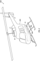
- FIG. 2 illustrates an exemplary configuration of an aircraft 1000 including the propulsion system 20 and its battery assembly 24.
- a housing 1002 e.g., a fuselage
- the battery packs 68 may be selectively installed into and selectively removed from the battery assembly 24, as will be discussed in further detail.
- the present disclosure is not limited to the foregoing exemplary configurations of the aircraft 1000 and the battery assembly 24 of FIG. 2 .
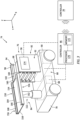
- FIG. 3 illustrates a battery replacement system 74 including at least one vehicle 76 configured for installing and removing the battery packs 68 from an aircraft (e.g., the aircraft 1000 of FIG. 2 ).
- the vehicle 76 of FIG. 3 includes a vehicle body 78, a propulsion assembly 80, a battery storage assembly 82, a battery transfer assembly 84, and a battery replacement controller 86.
- the propulsion assembly 80 may include a vehicle battery 88 and an electric motor 90.
- the vehicle battery 88 is configured to supply electrical power to the electric motor 90 to facilitate propulsion of the vehicle 76 (e.g., using one or more wheels coupled with the electric motor 90).
- the vehicle battery 88 may additionally supply electrical power for operation of one or more other assemblies or components of the vehicle such as, but not limited to, the battery storage assembly 82, the battery transfer assembly 84, and the battery replacement controller 86.
- the vehicle battery 88 may be configured as a rechargeable battery having a battery chemistry such as, but not limited to, lead acid, nickel cadmium (NiCd), nickel-metal hydride (Ni-MH), lithium-ion (Li-ion), lithium-polymer (Li-poly), lithium metal, and the like.
- the vehicle battery 88 and the electric motor 90 may be disposed within the vehicle body 78, for example, as schematically illustrated in FIG. 3 .
- the propulsion assembly 80 may further include steering equipment, position sensors (e.g., global positioning system (GPS) sensors), one or more cameras, Radar systems, proximity sensors (e.g., ultrasonic proximity sensors), and/or other equipment conventionally known in the art to facilitate autonomous movement and guidance of the vehicle 76 using the propulsion assembly 80.
- position sensors e.g., global positioning system (GPS) sensors
- GPS global positioning system
- Radar systems e.g., ultrasonic proximity sensors
- other equipment e.g., ultrasonic proximity sensors
- the battery storage assembly 82 of FIG. 3 includes a housing 92 and a plurality of rail assemblies 94.
- the housing 92 of FIG. 3 includes a first lateral housing panel 96 and a second lateral housing panel 98.
- the first lateral housing panel 96 and the second lateral housing panel 98 are mounted to or otherwise disposed on the vehicle body 78.
- the first lateral housing panel 96 and the second lateral housing panel 98 extend outward from the vehicle body 78 (e.g., vertically outward along the Z-axis).
- the first lateral housing panel 96 is laterally spaced from the second lateral housing panel 98 (e.g., along the X-axis).
- the rail assemblies 94 are disposed on and/or within the housing 92.
- Each of the rail assemblies 94 includes a first rail 100 and a second rail 102.
- the first rail 100 of FIG. 3 is disposed at (e.g., on, adjacent, or proximate) the first lateral housing panel 96 and the second rail 102 of FIG. 3 is disposed at (e.g., on, adjacent, or proximate) the second lateral housing panel 98.
- the present disclosure is not limited to foregoing exemplary configurations of the first rail 100 and the second rail 102.
- the first rail 100 is vertically aligned with the second rail 102 (e.g., along the Z-axis).
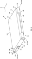
- FIG. 4 illustrates an exemplary configuration of the battery pack 68 for use with the vehicle 76 and the aircraft 1000 (see FIG. 2 ).
- the battery pack 68 of FIG. 4 includes a housing 104, a connection interface 106, and a rail assembly 108.
- the housing 104 extends between and to a first end 110 of the housing 104 and a second end 112 of the housing 104 (e.g., along the Y-axis).
- the housing 104 extends between and to a first lateral side 114 of the housing 104 and a second lateral side 116 of the housing 104.
- the housing 104 extends between and to a top side 118 of the housing 104 and a bottom side 120 of the housing 104.
- the connection interface 106 of FIG. 4 includes electrical connection terminals 122 (e.g., positive and negative terminals) for electrically connecting the battery pack 68 to the battery assembly 24 (see FIGS. 1 and 2 ), to an electrical charging system, and/or to the vehicle 76.
- the connection interface 106 may additionally include one or more signal communication terminals 124 configured to facilitate communication between the controller 26 (see FIG. 1 ) and/or the battery replacement controller 86 and the battery pack 68 (e.g., internal sensors, thermal control units, or other systems of the battery pack 68).
- the connection interface 106 of FIG. 4 is disposed at (e.g., on, adjacent, or proximate) the first end 110.
- the battery pack 68 may include one or more additional connection interfaces 106.
- the battery pack 68 may include a section connection interface 106 at (e.g., on, adjacent, or proximate) the second end 112.
- connection interface 106 e.g., on, adjacent, or proximate
- the rail assembly 108 of FIG. 4 is configured to facilitate translation (e.g., linear travel) of the battery pack 68 within a respective one of the rail assemblies 94 (e.g., along the Y-axis).
- FIG. 5 illustrates an exemplary relationship between the battery packs 68 and respective rail assemblies 94.
- the rail assembly 108 of FIGS. 4 and 5 includes a first rail 126 and a second rail 128.
- the first rail 126 of FIG. 4 is disposed at (e.g., on, adjacent, or proximate) the first side 114 and the second rail 128 of FIG. 4 is disposed at (e.g., on, adjacent, or proximate) the second lateral side 116.
- Each of the first rail 126 and the second rail 128 includes a shaft 130 and at least one rail portion 132.
- the shaft 130 extends (e.g., along the Y-axis) between and to a first shaft end 134 of the shaft 130 and a second shaft end 136 of the shaft 130.
- the first shaft end 134 may be disposed at (e.g., on, adjacent, or proximate) the first end 110.
- the second shaft end 136 may be disposed at (e.g., on, adjacent, or proximate) the second end 112.
- the at least one rail portion 132 may be configured for sliding engagement and/or locking engagement with the first rail 100 and the second rail 102.
- Each of the first rail 126 and the second rail 128 may include more than one rail portion 132.
- the first rail 126 and the second rail 128 of FIGS. 4 and 5 include a first rail portion 132A and a second rail portion 132B.
- the first rail portion 132A is disposed at (e.g., on, adjacent, or proximate) the first shaft end 134.
- the second rail portion 132B is disposed at (e.g., on, adjacent, or proximate) the second shaft end 136.
- the first rail 100 and the second rail of FIG. 3 are configured as female rails to receive the first rail 126 and the second rail 128, respectively, which are configured as male rails.
- the male and female rail configurations of the battery storage assembly 82 and the battery packs 68 may be interchangeable.
- the battery storage assembly 82 may include a linear actuator configured to effect linear translation (e.g., linear travel along the Y-axis) of the battery packs 68 to move the battery packs 68 into, out of, and within the battery storage assembly 82 (e.g., for a respective one of the rail assemblies 94).
- each rail assembly 94 may include a linear actuator 144.
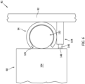
- FIG. 6 illustrates a cutaway view of the linear actuator 144 with a portion of one of the battery packs 68 and one of the rail assemblies 94.
- the linear actuator 144 of FIG. 6 is configured as a rack and pinion linear actuator. However, the present disclosure is not limited to this particular configuration of the linear actuator 144.
- the battery transfer assembly 84 is configured to facilitate transfer of the battery packs 68 from the battery assembly 24 (see FIGS. 1 and 2 ) to the battery storage assembly 82 and from the battery storage assembly 82 to the battery assembly 24.
- the battery transfer assembly 84 of FIG. 3 includes a battery transfer tray 150 and an actuator 152.
- the battery transfer tray 150 of FIG. 3 includes a tray panel 154 and a rail assembly 156.
- the tray panel 154 extends between and to a first end 158 of the tray panel 154 and a second end 160 of the tray panel 154.
- the tray panel 154 extends between and to a first lateral side 162 of the tray panel 154 and a second lateral side 164 of the tray panel 154.
- the rail assembly 156 includes a first rail 166 and a second rail 168.
- the first rail 166 of FIG. 3 is disposed at (e.g., on, adjacent, or proximate) the first lateral side 162 and the second rail 168 of FIG.
- the battery transfer tray 150 may additionally include a linear actuator, similar to the linear actuator 144, to effect linear translation (e.g., linear travel along the Y-axis) of the battery packs 68 to move the battery packs 68 into, out of, and within the battery transfer tray 150.
- a linear actuator similar to the linear actuator 144, to effect linear translation (e.g., linear travel along the Y-axis) of the battery packs 68 to move the battery packs 68 into, out of, and within the battery transfer tray 150.
- the actuator 152 interconnects the battery transfer tray 150 and the vehicle body 78.
- the actuator 152 of FIG. 3 extends outward (e.g., along the Z-axis) from the vehicle body 78 to the battery transfer tray 150.
- the actuator 152 is configured to move the battery transfer tray 150 (e.g., along the Z-axis) to align the battery transfer tray 150 with one of the rail assemblies 94 of the battery storage assembly 82 or one of the ports 1004 of the aircraft 1000 (see FIG. 2 ).
- the actuator 152 may be further configured to tilt the battery transfer tray 150 (e.g., relative to the Z-axis) to accommodate uneven airport tarmac conditions or other relative positional differences between the aircraft 1000 and the vehicle 76.
- the actuator 152 may be, for example, a hydraulic actuator, a pneumatic actuator, a electro-mechanical actuator, or any other actuator conventionally known in the art and suitable for selectively positioning the battery transfer tray 150.
- the battery replacement controller 86 includes a processor 170 connected in signal communication with memory 172.
- the processor 170 may include any type of computing device, computational circuit, processor(s), CPU, computer, or the like capable of executing a series of instructions that are stored in the memory 172. Instructions can be directly executable or can be used to develop executable instructions. For example, instructions can be realized as executable or non-executable machine code or as instructions in a high-level language that can be compiled to produce executable or non-executable machine code. Further, instructions also can be realized as or can include data. Computer-executable instructions also can be organized in any format, including routines, subroutines, programs, data structures, objects, modules, applications, applets, functions, etc.
- the instructions may include an operating system, and/or executable software modules such as program files, system data, buffers, drivers, utilities, and the like.
- the executable instructions may apply to any functionality described herein to enable the vehicle 76 to accomplish the same algorithmically and/or by coordination of vehicle 76 components.
- the battery replacement controller 86 may be connected in signal communication with the electric motor 90, the steering equipment, and/or the sensors of the propulsion assembly 80 to autonomously control movement of the vehicle 76.
- the battery replacement controller 86 may be further connected in signal communication with one or more of the battery packs 68 (e.g., stored by the battery storage assembly 82) to identify temperature, current, voltage, and state of charge (SoC) of the battery packs 68.
- SoC state of charge
- the memory 172 may include a single memory device or a plurality of memory devices; e.g., a computer-readable storage device that can be read, written, or otherwise accessed by a general purpose or special purpose computing device, including any processing electronics and/or processing circuitry capable of executing instructions.
- the present disclosure is not limited to any particular type of memory device, which may be non-transitory, and may include read-only memory, random access memory, volatile memory, non-volatile memory, static memory, dynamic memory, flash memory, cache memory, volatile or non-volatile semiconductor memory, optical disk storage, magnetic disk storage, magnetic tape, other magnetic storage devices, or any other medium capable of storing one or more instructions, and/or any device that stores digital information.
- the memory device(s) may be directly or indirectly coupled to the battery replacement controller 86.
- the battery replacement controller 86 may include, or may be in communication with, an input device that enables a user to enter data and/or instructions, and may include, or be in communication with, an output device configured, for example to display information (e.g., a visual display or a printer), or to transfer data, etc. Communications between the controller 86 and other electrical and/or electronic components (e.g., controllers, sensors, etc.) may be via a hardwire connection or via a wireless connection.
- portions of the controller 86 may assume various forms (e.g., digital signal processor, analog device, etc.) capable of performing the functions described herein.
- the battery replacement controller 86 of FIG. 3 includes or is otherwise connected in signal communication with a user interface terminal 174.
- the user interface terminal 174 may include a display, a touchscreen, a keyboard, or any other combination of input and output devices to allow a pilot or other operator to provide data and/or instructions to the battery replacement controller 86 using the user interface terminal 174.
- the user interface terminal 174 may be disposed on the vehicle 76.
- the user interface terminal 174 of FIG. 3 is disposed on the first lateral housing panel 96.
- the battery replacement controller 86 may additionally be connected in signal communication (e.g., wireless communication) with the controller 26.
- the battery replacement controller 86 may be configured to receive data associated with the aircraft 1000 flight plan, the status of the battery packs 68 installed in the battery assembly 24, or other information, as will be discussed in further detail.
- the controller 26 and the battery replacement controller 86 may be configured to allow the pilot or other operator to provide data and/or instructions to the battery replacement controller 86 from the aircraft 1000 via the controller 26.
- FIG. 7 illustrates a flowchart for the Method 700.
- the Method 700 will be described herein with respect to the aircraft 1000, the aircraft propulsion system 20, and the vehicle 76.
- the controller 26 e.g., the processor 70
- the battery replacement controller 86 e.g., the processor 170
- the processor 170 may execute instructions stored in memory 172, thereby causing the controller 86 and/or its processor 170 to execute or otherwise control one or more steps of the Method 700.
- Method 700 is not limited to use with the aircraft 1000, the aircraft propulsion system 20, or the vehicle 76. Unless otherwise noted herein, it should be understood that the steps of Method 700 are not required to be performed in the specific sequence in which they are discussed below and, in some embodiments, the steps of Method 700 may be performed separately or simultaneously.
- Step 702 includes identifying an energy storage prerequisite for the aircraft 1000 and its battery assembly 24.
- the energy storage prerequisite refers to a minimum amount of energy (e.g., an energy storage threshold) stored by all of the battery packs 68 installed in the battery assembly 24 combined, which may be required for an immediately subsequent flight or series of flights of the aircraft 1000.
- the battery replacement controller 86 may identify the energy storage prerequisite for the aircraft 1000 using information received from a pilot or other operator (e.g., from the user interface terminal 174) and/or from the controller 26. For example, a pilot for the aircraft 1000 may enter flight plan information for the immediately subsequent flight or series of flights of the aircraft 1000 into the user interface terminal 174, and the battery replacement controller 86 may use the flight plan information to identify the energy storage prerequisite for the aircraft 1000.
- the flight plan information may include information such as, but not limited to, a departure location, a landing location, a flight distance, an aircraft model for the aircraft 1000, a number of passengers (e.g., "souls on board"), aircraft 1000 weight, anticipated weather conditions, additional backup power requirements, and the like.
- the battery replacement controller 86 may apply the flight plan information to one or more databases or look-up tables (e.g., stored in the memory 172) to identify the energy storage prerequisite for the immediately subsequent flight or series of flights of the aircraft 1000. Identifying the energy storage prerequisite may additionally include applying a safety margin to the energy storage prerequisite to account for additional, unplanned energy demand for the battery packs 68.
- Step 704 may optionally be performed to identify a current state of charge (SoC) for the battery packs 68 installed in the battery assembly 24.
- the controller 26 may identify a SoC for each of the battery packs 68 installed in the battery assembly 24 and provide the SoC for each of the battery packs to the battery replacement controller 86.
- Identifying the current SoC for the battery packs 68 installed in the battery assembly 24 may include identifying a SoC hierarchy for the battery packs 68.
- the controller 26 and/or the battery replacement controller 86 may identify the one of the battery packs 68 having the lowest SoC, the one of the battery packs 68 having the second lowest SoC, etc., such that all of the battery packs 68 are classified in order of their relative SoC.
- Step 706 includes identifying a battery pack 68 loadout plan for the aircraft 1000 and its battery assembly 24.
- the battery replacement controller 86 may identify the battery pack 68 loadout plan for the aircraft 1000 using the identified energy storage prerequisite (see Step 702), the identified current SoC for the battery packs 68 installed in the battery assembly 24, the battery packs 68 stored in the battery storage assembly 82 (e.g., via the connection interface 106), and/or the battery packs 68 stored outside the battery storage assembly 82 but otherwise stored and/or maintained by the battery replacement system 74 (e.g., on a separate vehicle 76, fixed battery pack storage assembly, etc.).
- the battery pack 68 loadout plan includes the specific battery packs 68 which will be installed on the aircraft 1000 and its battery assembly 24 in preparation for the immediately subsequent flight or series of flights of the aircraft 1000 to satisfy the identified energy storage prerequisite.
- the specific battery packs 68 identified in the battery pack 68 loadout plan may include battery packs 68 currently installed on the aircraft 1000 and its battery assembly 24, battery packs 68 stored in the battery storage assembly 82, battery packs 68 stored outside the battery storage assembly 82 but otherwise stored and/or maintained by the battery replacement system 74, and/or combinations thereof.
- the battery replacement controller 86 selects the specific battery packs 68 of the battery pack 68 loadout plan such that the total SoC of the battery packs 68 identified by the battery pack 68 loadout plan is greater than or equal to the identified energy storage prerequisite.
- the battery replacement controller 86 may identify that the battery packs 68 currently installed on the aircraft 1000 and its battery assembly 24 have a sufficient combined SoC for the immediately subsequent flight or series of flights of the aircraft 1000. In this case, the vehicle 76 may take no further action to control the battery pack 68 loadout for the aircraft 1000 and its battery assembly 24.
- the battery replacement controller 86 may identify the battery pack 68 loadout plan using the SoC hierarchy to minimize a number of battery pack 68 replacements which may be performed to execute the battery pack 68 loadout plan.
- the battery pack 68 loadout plan may include instructions for replacing the lowest SoC battery pack 68 installed on the aircraft 1000 and its battery assembly 24 with another of the battery packs 68 stored in the battery storage assembly 82, which another of the battery packs 68 may be fully or substantially fully charged or may have a SoC which is greater than the lowest SoC battery pack 68.
- the battery replacement controller 86 may identify the battery pack 68 loadout plan to include a quantity of the battery packs 68 which is less than a capacity of the battery packs 68 (e.g., a maximum quantity of installed battery packs 68) provided by the aircraft 1000 and its battery assembly 24.
- a capacity of the battery packs 68 e.g., a maximum quantity of installed battery packs 68
- the aircraft 1000 and its battery assembly 24 may have a capacity for five battery packs 68 and the battery replacement controller 86 may identify the battery pack 68 loadout plan to include four battery packs 68 which satisfy the identified energy storage prerequisite.
- the battery replacement controller 86 may facilitate a reduction in aircraft 1000 weight and, thereby, improve efficiency of the aircraft 1000.
- Step 708 includes controlling the battery pack 68 loadout for the aircraft 1000 in accordance with the identified battery pack 68 loadout plan (see Step 706).
- the battery replacement controller 86 may control components of the vehicle 76 to remove one or more of the battery packs 68 current installed on the aircraft 1000 and its battery assembly 24 and/or to install one or more of the battery packs 68 stored by the battery storage assembly 82 into the aircraft 1000 and its battery assembly 24.
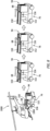
- FIG. 8 illustrates an exemplary battery pack 68 removal sequence using the vehicle 76.
- the battery replacement controller 86 may control components of the vehicle 76 to effect removal and storage of one or more of the battery packs 68 installed in the aircraft 1000 and its battery assembly 24, as identified in the battery pack 68 loadout plan.
- the battery replacement controller 86 may control a position of the battery transfer tray 150 (e.g., using the actuator 152) to align the battery transfer tray 150 with one of the ports 1004 of the aircraft 1000.
- the battery pack 68 of FIG. 8 may be removed (e.g., electrically and physically disconnected) from the battery assembly 24 by the battery transfer tray 150 and/or the battery assembly 24, and thereby positioned onto the battery transfer tray 150 (e.g., the rail assembly 156).
- FIG. 9 illustrates an exemplary battery pack 68 installation sequence using the vehicle 76.
- the battery replacement controller 86 may control components of the vehicle 76 to effect installation of one or more of the battery packs 68 stored in the battery storage assembly 82 into the aircraft 1000 and its battery assembly 24, as identified in the battery pack 68 loadout plan.
- the battery replacement controller 86 may control a position of the battery transfer tray 150 (e.g., using the actuator 152) to align the battery transfer tray 150 with one of the plurality of rail assemblies 94 storing one of the battery packs 68 to be installed into the aircraft 1000 and its battery assembly 24 in accordance with the battery pack 68 loadout plan.
- the battery pack 68 of FIG. 9 may be moved from the one of the plurality of rail assemblies 94 to the battery transfer tray 150.
- the battery replacement controller 86 may then control a position of the battery transfer tray 150 (e.g., using the actuator 152) to align the battery transfer tray 150 with one of the ports 1004 of the aircraft 1000.
- the battery pack 68 of FIG. 9 may be moved from the battery transfer tray 150 to one of the ports 1004 of the aircraft 1000 and installed into the aircraft 1000 and electrically and physically connected with the battery assembly 24.
- Step 710 may optionally be performed to charge one or more of the battery packs 68 stored by the battery storage assembly 82.
- the battery replacement controller 86 may control the vehicle 76 to move to a location of a battery charging station and position (e.g., electrically connect) the battery packs 68 stored in the battery storage assembly 82 to be directly charged by the battery charging station or indirectly through an electrical connection between the vehicle 76 (e.g., the battery storage assembly 82) and the connection interface 106 (e.g., the electrical connection terminals 122).
- the vehicle 76 may be configured to charge the battery packs 68 using energy stored by the vehicle battery 88.
- the vehicle 76 may be connected to the battery charging station to charge the vehicle battery 88 and the vehicle 76 may additionally charge the battery packs 68 using electrical power from the battery charging station.
- any one of these structures may describe the operations as a sequential process, many of the operations can be performed in parallel or concurrently.
- the order of the operations may be rearranged.
- a process may correspond to a method, a function, a procedure, a subroutine, a subprogram, etc.
Landscapes
- Engineering & Computer Science (AREA)
- Chemical & Material Sciences (AREA)
- Chemical Kinetics & Catalysis (AREA)
- Electrochemistry (AREA)
- General Chemical & Material Sciences (AREA)
- Aviation & Aerospace Engineering (AREA)
- Mechanical Engineering (AREA)
- Power Engineering (AREA)
- Transportation (AREA)
- Life Sciences & Earth Sciences (AREA)
- Sustainable Development (AREA)
- Sustainable Energy (AREA)
- Manufacturing & Machinery (AREA)
- Combustion & Propulsion (AREA)
- Charge And Discharge Circuits For Batteries Or The Like (AREA)
- Battery Mounting, Suspending (AREA)
- Secondary Cells (AREA)
Applications Claiming Priority (1)
| Application Number | Priority Date | Filing Date | Title |
|---|---|---|---|
| US18/219,278 US20250010757A1 (en) | 2023-07-07 | 2023-07-07 | Systems and methods for controlling a battery pack loadout for an aircraft |
Publications (1)
| Publication Number | Publication Date |
|---|---|
| EP4491444A1 true EP4491444A1 (fr) | 2025-01-15 |
Family
ID=91898384
Family Applications (1)
| Application Number | Title | Priority Date | Filing Date |
|---|---|---|---|
| EP24187243.1A Pending EP4491444A1 (fr) | 2023-07-07 | 2024-07-08 | Systèmes et procédés de commande d'une mise sous échange de bloc-batterie pour un aéronef |
Country Status (3)
| Country | Link |
|---|---|
| US (1) | US20250010757A1 (fr) |
| EP (1) | EP4491444A1 (fr) |
| CA (1) | CA3247365A1 (fr) |
Families Citing this family (1)
| Publication number | Priority date | Publication date | Assignee | Title |
|---|---|---|---|---|
| US11999509B2 (en) * | 2021-05-17 | 2024-06-04 | Pratt & Whitney Canada Corp. | Hybrid-electric and all-electric aircraft power systems |
Citations (5)
| Publication number | Priority date | Publication date | Assignee | Title |
|---|---|---|---|---|
| CN205564859U (zh) * | 2016-05-10 | 2016-09-07 | 傲飞创新科技(深圳)有限公司 | 无人机电池盒装载结构 |
| CN212529379U (zh) * | 2020-06-03 | 2021-02-12 | 王盛会 | 一种移动换电专项作业车 |
| CN113442779A (zh) * | 2020-03-25 | 2021-09-28 | 广东博智林机器人有限公司 | 一种电池取放托盘、电池更换机器人及电池更换方法 |
| CN214420251U (zh) * | 2021-03-29 | 2021-10-19 | 厦门金龙联合汽车工业有限公司 | 一种移动换电设备 |
| US20220258645A1 (en) * | 2021-02-16 | 2022-08-18 | Archer Aviation, Inc. | Systems and methods for managing a network of electric aircraft batteries |
-
2023
- 2023-07-07 US US18/219,278 patent/US20250010757A1/en active Pending
-
2024
- 2024-07-05 CA CA3247365A patent/CA3247365A1/en active Pending
- 2024-07-08 EP EP24187243.1A patent/EP4491444A1/fr active Pending
Patent Citations (5)
| Publication number | Priority date | Publication date | Assignee | Title |
|---|---|---|---|---|
| CN205564859U (zh) * | 2016-05-10 | 2016-09-07 | 傲飞创新科技(深圳)有限公司 | 无人机电池盒装载结构 |
| CN113442779A (zh) * | 2020-03-25 | 2021-09-28 | 广东博智林机器人有限公司 | 一种电池取放托盘、电池更换机器人及电池更换方法 |
| CN212529379U (zh) * | 2020-06-03 | 2021-02-12 | 王盛会 | 一种移动换电专项作业车 |
| US20220258645A1 (en) * | 2021-02-16 | 2022-08-18 | Archer Aviation, Inc. | Systems and methods for managing a network of electric aircraft batteries |
| CN214420251U (zh) * | 2021-03-29 | 2021-10-19 | 厦门金龙联合汽车工业有限公司 | 一种移动换电设备 |
Also Published As
| Publication number | Publication date |
|---|---|
| CA3247365A1 (en) | 2025-06-06 |
| US20250010757A1 (en) | 2025-01-09 |
Similar Documents
| Publication | Publication Date | Title |
|---|---|---|
| EP4461939A1 (fr) | Système et procédé de commande d'un propulseur pour un système de propulsion d'aéronef hybride-électrique | |
| EP4524384A1 (fr) | Ensemble moteur pour système de propulsion d'aéronef | |
| EP4530454A1 (fr) | Système et procédé de commande de système de propulsion d'aéronef hybride-électrique | |
| EP4491444A1 (fr) | Systèmes et procédés de commande d'une mise sous échange de bloc-batterie pour un aéronef | |
| US12006052B2 (en) | Electrical power system for a vehicle | |
| EP4415216A1 (fr) | Système et procédé de commande d'un ensemble batterie d'aéronef | |
| EP4491443A1 (fr) | Systèmes et procédés de commande d'une mise sous charge de bloc-batterie pour un aéronef | |
| EP4467803A1 (fr) | Systèmes et procédés de commande d'un système de distribution électrique pour un système de propulsion d'aéronef hybride-électrique | |
| EP4415213A2 (fr) | Système et procédé de commande d'un ensemble batterie d'aéronef | |
| US12545418B2 (en) | Control assembly for aircraft propulsion systems | |
| US20260001653A1 (en) | Systems and methods for controlling an electric motor of an aircraft propulsion system | |
| US12565325B1 (en) | Propulsor reverse rotation protection for hybrid-electric aircraft propulsion systems | |
| EP4726963A1 (fr) | Ensemble électrique et procédés de connexion/déconnexion | |
| EP4685058A1 (fr) | Ensemble d'alimentation externe d'aéronef, ensemble d'alimentation au sol et procédé de fonctionnement | |
| EP4707177A1 (fr) | Ensemble propulsif pour aéronef et ses procédés de fonctionnement | |
| US12545419B1 (en) | Emergency energy protection assembly for hybrid-electric aircraft propulsion systems | |
| EP4415214A2 (fr) | Système et procédé de charge de batterie d'aéronef | |
| EP4415215A2 (fr) | Système et procédé de charge de batterie d'aéronef | |
| US20260103082A1 (en) | Battery management system temperature sensing systems and methods | |
| US20260103081A1 (en) | Battery management system temperature sensing systems and methods | |
| US20260104294A1 (en) | Battery management system temperature sensing systems and methods |
Legal Events
| Date | Code | Title | Description |
|---|---|---|---|
| PUAI | Public reference made under article 153(3) epc to a published international application that has entered the european phase |
Free format text: ORIGINAL CODE: 0009012 |
|
| STAA | Information on the status of an ep patent application or granted ep patent |
Free format text: STATUS: THE APPLICATION HAS BEEN PUBLISHED |
|
| AK | Designated contracting states |
Kind code of ref document: A1 Designated state(s): AL AT BE BG CH CY CZ DE DK EE ES FI FR GB GR HR HU IE IS IT LI LT LU LV MC ME MK MT NL NO PL PT RO RS SE SI SK SM TR |
|
| STAA | Information on the status of an ep patent application or granted ep patent |
Free format text: STATUS: REQUEST FOR EXAMINATION WAS MADE |
|
| 17P | Request for examination filed |
Effective date: 20250715 |