EP4491461A1 - Unité de support pour un porte-vélo - Google Patents
Unité de support pour un porte-vélo Download PDFInfo
- Publication number
- EP4491461A1 EP4491461A1 EP24187516.0A EP24187516A EP4491461A1 EP 4491461 A1 EP4491461 A1 EP 4491461A1 EP 24187516 A EP24187516 A EP 24187516A EP 4491461 A1 EP4491461 A1 EP 4491461A1
- Authority
- EP
- European Patent Office
- Prior art keywords
- holding element
- holding
- movable
- pivot axis
- lever
- Prior art date
- Legal status (The legal status is an assumption and is not a legal conclusion. Google has not performed a legal analysis and makes no representation as to the accuracy of the status listed.)
- Pending
Links
Images





Classifications
-
- B—PERFORMING OPERATIONS; TRANSPORTING
- B60—VEHICLES IN GENERAL
- B60R—VEHICLES, VEHICLE FITTINGS, OR VEHICLE PARTS, NOT OTHERWISE PROVIDED FOR
- B60R9/00—Supplementary fittings on vehicle exterior for carrying loads, e.g. luggage, sports gear or the like
- B60R9/08—Supplementary fittings on vehicle exterior for carrying loads, e.g. luggage, sports gear or the like specially adapted for sports gear
- B60R9/10—Supplementary fittings on vehicle exterior for carrying loads, e.g. luggage, sports gear or the like specially adapted for sports gear for cycles
-
- B—PERFORMING OPERATIONS; TRANSPORTING
- B60—VEHICLES IN GENERAL
- B60R—VEHICLES, VEHICLE FITTINGS, OR VEHICLE PARTS, NOT OTHERWISE PROVIDED FOR
- B60R9/00—Supplementary fittings on vehicle exterior for carrying loads, e.g. luggage, sports gear or the like
- B60R9/06—Supplementary fittings on vehicle exterior for carrying loads, e.g. luggage, sports gear or the like at vehicle front or rear
Definitions
- the invention relates to a support unit for a bicycle carrier, comprising a holding device which is designed to hold a mounting section mounted on a bicycle fork, in particular a thru axle, wherein the holding device has a fixed holding element, a movable holding element and a holding recess formed between the fixed holding element and the movable holding element, and wherein the movable holding element is movable relative to the fixed holding element between an opening position in which the holding receptacle is open to receive the mounting section, and a holding position in which the holding receptacle is closed to hold the mounting section.
- Such a carrying unit is from the EP 3 838 678 B1 known and has a holding device referred to as a locking mechanism with a fixed holding element (locking component) and a movable holding element (movable locking component).
- the holding device of the known support unit is designed to hold a mounting section mounted on a bicycle fork.
- the movable holding element is movable relative to the fixed holding element between an open position and a holding position. In the open position, a holding receptacle formed between the two holding elements is open for receiving the mounting section. In the holding position, the holding receptacle for holding the mounting section is closed.
- the holding device is designed to be displaceable into the holding position by absorbing a force transmitted by the mounting section when inserting the mounting section.
- the object of the invention is to provide a support unit of the type mentioned above, which offers advantages over the prior art.
- the support unit has a clamping device which is designed to move the movable holding element between the open position and the holding position and to lock the movable holding element in the holding position, wherein the clamping device has a toggle lever mechanism which is operatively connected to the movable holding element for moving and locking the same and is movable within a plane of movement.
- the solution according to the invention enables simplified operation of the support unit. At the same time, a simple structure of the support unit and a particularly reliable locking of the movable holding element in the holding position.
- the clamping device according to the invention is equipped with the said toggle lever mechanism.
- the toggle lever mechanism serves to move and lock the movable holding element.
- the toggle lever mechanism is operatively connected to the movable holding element.
- the movable holding element can be moved in different ways between the open position and the holding position.
- the movable holding element can be moved in a translational manner.
- the movable holding element can alternatively or additionally be displaced in a rotational and/or pivotal manner.
- the movement of the movable holding element between the open position and the holding position takes place in the movement plane of the toggle lever mechanism.
- the said movement takes place in a further movement plane (of the movable holding element) that is oriented transversely, preferably orthogonally, to the movement plane of the toggle lever mechanism.
- the toggle lever mechanism is overextended in the holding position, the locking of the movable holding element being effected by said overextension.
- overextending the toggle lever mechanism in the holding position of the movable holding element reliable locking can be achieved in a structurally simple manner.
- a separate locking mechanism can be dispensed with.
- "Overextended" means that the toggle lever mechanism is moved beyond a dead center, i.e. beyond a point from which further movement of the toggle lever mechanism does not cause further movement of the movable holding element in the direction of the holding position.
- the clamping device has a compensation device by means of which the toggle lever mechanism is elastically supported in a limited translational manner relative to the fixed holding element in the plane of movement, wherein the elastic support causes a size compensation that enables locking of the movable holding element for holding assembly sections of different sizes in holding positions of the movable holding element that are closed to different degrees.
- This embodiment of the invention makes it possible to use the holding device for assembly sections of different sizes, in particular for plug-in axles with different diameters.
- the compensation device enables reliable locking by means of the toggle lever mechanism to be achieved regardless of the size of the assembly section, for example the diameter of the plug-in axle.
- the toggle lever mechanism is supported by means of the compensation device relative to the fixed
- the holding element is elastically supported in a limited, translationally movable manner, with the mobility being provided in the plane of movement of the toggle lever mechanism.
- the said elastic support enables a compensating movement of the toggle lever mechanism.
- This compensating movement enables the said size compensation, so that functional kinematics of the toggle lever mechanism are guaranteed even for assembly sections of different sizes.
- the toggle lever mechanism engages the movable holding element at one end and is supported on the compensating device at the other end.
- the toggle lever mechanism itself has the said compensating function, for example in that at least one lever of the toggle lever mechanism is designed to be elastically flexible, in particular elastically bendable.
- the compensating device has at least one compensating spring that is elastically movable in the plane of movement and that is supported at one end relative to the fixed holding element and at the other end acts on the toggle lever mechanism.
- the at least one compensating spring serves to provide elastically movable support for the toggle lever mechanism.
- the compensating spring is preferably a helical spring.
- the compensating device has an elastically flexible elastomer element or the like instead of a compensating spring.
- the movable holding element is mounted on the fixed holding element within the plane of movement of the toggle lever mechanism relative to the fixed holding element so that it can pivot about a first pivot axis.
- the pivoting mobility of the movable holding element in the plane of movement of the toggle lever mechanism and its mounting on the fixed holding element means that the structure of the support unit can be simplified even further.
- the first pivot axis is orthogonal to the plane of movement of the toggle lever mechanism.
- the movable holding element is pivoted open relative to the fixed holding element in the open position, i.e. moved away from the fixed holding element about the first pivot axis. In the holding position, the movable holding element is pivoted about the first pivot axis towards the fixed holding element.
- the movable holding element can be pivoted by at least 60°, preferably at least 80°, particularly preferably at least 90° around the first pivot axis by means of the toggle lever mechanism. This ensures that the holding recess is sufficiently wide open in the open position so that the mounting section, in particular the plug-in axle, can be moved without hitting the two Holding elements can be inserted into the holding recess. This makes the operation of the carrying unit even more comfortable.
- a spring element acts on the movable holding element, whereby the movable holding element is pre-tensioned in the direction of the open position by means of the spring element.
- the pre-tensioning of the movable holding element in the direction of the open position by means of the spring element counteracts a (intentional or unintentional) displacement into the holding position. This can prevent the holding element from being displaced in the direction of the holding position when the assembly section is inserted before the holding recess is reached, thereby unintentionally blocking the holding recess.
- the pre-tensioning in the direction of the open position causes a play-free movement by means of the toggle lever mechanism. For example, this can result in an improved quality impression for the operator.
- the toggle lever mechanism has an actuating lever and a supporting lever, wherein the actuating lever is mounted on the movable holding element so as to be pivotable about a second pivot axis relative to the movable holding element, wherein the supporting lever is connected to the fixed holding element so as to be pivotable about a third pivot axis relative to the fixed holding element, and wherein the actuating lever and the supporting lever are mounted on one another so as to be pivotable about a fourth pivot axis relative to one another.
- This embodiment of the invention offers a particularly simple structure of the toggle lever mechanism.
- the actuating lever is preferably designed for (direct) manual actuation of the toggle lever mechanism.
- the actuating lever can have an actuating section for this purpose which is designed for manual gripping by an operator.
- the actuating lever is instead connected to another lever of the toggle lever mechanism which is designed for (direct) manual actuation.
- the actuating lever is preferably mounted directly on the movable holding element.
- the support lever is pivotally mounted on the actuating lever about the fourth pivot axis (and vice versa) and is pivotally connected to the fixed holding element about the third pivot axis relative to the fixed holding element.
- the said connection of the support lever to the fixed holding element can be direct or indirect.
- the second pivot axis, the third pivot axis and the fourth pivot axis are parallel.
- the second pivot axis, the third pivot axis and the fourth pivot axis are orthogonal to the plane of movement. If the clamping device has a compensation device according to the previous description, the second pivot axis, the third pivot axis and the fourth pivot axis move within the plane of movement when the toggle lever mechanism moves. If no compensation device is present, only the second pivot axis and the fourth pivot axis are movable in this way, whereas the third pivot axis is stationary with respect to the plane of movement.
- the third pivot axis is supported by the compensation device on the fixed holding element in the plane of movement in a limited, translationally movable manner. Consequently, in this embodiment, the compensation device acts on the support lever in the region of the third pivot axis.
- the second pivot axis and the third pivot axis are connected to one another by an imaginary connecting line extending in the plane of movement, whereby during a movement from the open position to the holding position the fourth pivot axis moves over the connecting line, causing the toggle lever mechanism to overextend.
- the toggle lever mechanism reaches its dead center as soon as the fourth pivot axis reaches the imaginary connecting line (intersection of the connecting lines of the movement path of the fourth pivot axis within the plane of movement). By moving the fourth pivot axis over the connecting line, the toggle lever mechanism is overextended. When the dead center is reached, a further pivoting movement of the actuating lever cannot cause any further movement of the movable holding element in the direction of the holding position.
- the toggle lever mechanism has a fixing lever, wherein the fixing lever is mounted on the actuating lever so as to be pivotable about a fifth pivot axis relative to the actuating lever and has a stop section, wherein the stop section presses on the support lever in the holding position to fix the toggle lever mechanism, and wherein the stop section can be lifted off the support lever by means of a pivoting movement of the fixing lever about the fifth pivot axis to release the fixation.
- the fixing lever enables a structurally simple and reliable fixation of the toggle lever mechanism in the holding position. Said fixation can act as an alternative or in addition to any overextension of the toggle lever mechanism.
- the stop section of the fixing lever presses on a section of the support lever provided for this purpose.
- the fixing lever is mounted on the actuating lever so that it can pivot about the fifth pivot axis.
- the fifth pivot axis is preferably orthogonal to the plane of movement.
- the fifth pivot axis is preferably parallel to the second pivot axis, the third pivot axis and/or the fourth pivot axis of the toggle lever mechanism.
- the tensioning device has a lockable lock, wherein the lock is arranged on the actuating lever and, in a locked state, interacts with the support lever to block the mobility of the toggle lever mechanism.
- the lockable lock prevents unwanted manipulation of the tensioning device.
- the mobility of the toggle lever mechanism can be blocked by means of the lockable lock.
- the lock is arranged on the actuating lever and, in the holding position, can be brought into engagement with a section of the support lever provided for this purpose, i.e. locked. This engagement creates a mechanical operative connection between the actuating lever and the support lever, which prevents movement in the direction of the open position. This operative connection can be canceled by unlocking the lock.
- the lockable lock can have any suitable design.
- the movable holding element is movable from the open position into a rest position in which the holding receptacle for, in particular temporarily, holding the mounting section is at least partially closed and/or less wide than in the holding position, and in which the toggle lever mechanism is releasably locked by means of a locking device against an unwanted displacement of the movable holding element in the direction of the open position.
- the said rest position is provided as a further defined position in addition to the open position and the holding position. The rest position serves to only temporarily hold the mounting section and allows a significantly simplified fastening of the bicycle fork and thus of the entire bicycle.
- the actual fastening process of the bicycle in the rest position can be temporarily interrupted by the operator and continued later without having to fear that the bicycle to be fastened will fall over.
- the rest position is a defined intermediate position between the open position and the Holding position. In the rest position, the holding receptacle of the holding device is at least partially closed and/or less closed than in the holding position. In this way, the rest position allows the assembly section to be temporarily held, which can also be referred to as pre-fixing.
- the rest position is not intended for the actual transport of the bicycle.
- the holding position is for this purpose.
- the toggle lever mechanism is locked in the rest position by means of the locking device.
- the locking works in the direction of the open position.
- the locking works exclusively in the direction of the open position and therefore not additionally in the direction of the holding position.
- the locking is releasable.
- the movable holding element, the holding device and/or the tensioning device is designed in such a way that the said displacement in the direction of the rest position occurs automatically under a weight of a maximum of 60 N, preferably a maximum of 50 N, more preferably a maximum of 40 N, more preferably a maximum of 30 N, more preferably a maximum of 20 N.
- the fixing lever has the first locking section, which in the rest position releasably interacts with the second locking section in a form-fitting manner.
- the second locking section is firmly connected to the support lever.
- the first locking section is an integral section of the fixing lever.
- the second locking section is an integral section of the support lever.
- the first locking section and the second locking section can basically be designed in any way suitable for the present purpose.
- the first locking section is designed in the form of a hook and the second locking section is designed in the form of an undercut to which the hook is releasably hooked in the rest position.
- the invention also relates to a bicycle carrier with a support unit according to the above description.
- the bicycle carrier is a roof rack for a passenger car.
- the bicycle carrier has an elongated support rail, wherein the support unit is attached to one end of the support rail.
- the support rail is preferably supported on cross members of the bicycle carrier. The said cross members are attached to the motor vehicle, in particular the motor vehicle roof, in a manner known to those skilled in the art.
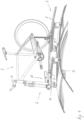
- a bicycle carrier 1 is mounted on a vehicle roof D of a passenger car shown in sections (without reference symbol) and serves to carry a bicycle F.
- the bicycle carrier 1 is therefore designed in the form of a roof bicycle carrier. In an embodiment not shown in the figures, the bicycle carrier is designed as a rear bicycle carrier.
- the bicycle carrier 1 has a support rail 2, a front cross member 3 and a rear cross member 4.
- the two cross members 3, 4 are attached to the vehicle roof D in a manner known to those skilled in the art.
- the two cross members 3, 4 are aligned parallel to a transverse axis of the vehicle roof D.
- the support rail 2 is between the front cross member 3 and the rear cross member 4 longitudinally extended and attached to the front cross member 3 and to the rear cross member 4.
- the support rail 2 is in this case parallel to a longitudinal axis of the vehicle roof D.
- the bicycle carrier 1 has only a single support rail 2. It is understood that the bicycle carrier can also be provided with several parallel support rails so that, for example, two or three bicycles can be held and transported at the same time.
- the support unit 10 is arranged on the front of the support rail 2 and connected to it.
- the support unit 10 serves for the detachable fastening of a bicycle fork G of the bicycle F.
- the support unit instead serves for the detachable fastening of the rear dropouts (without reference symbol) of the bicycle and is arranged on the rear of the support rail for this purpose and is firmly connected to it.
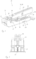
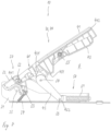
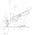
- the support unit 10 is shown in detail in the Fig. 2 to 13 shown.
- the support unit 10 has a holding device 20 and a tensioning device 30. In the embodiment shown, the support unit 10 also has a compensating device 50 and a lockable lock 60. The compensating device 50 and the lockable lock 60 are optional and are not present in all embodiments.
- the holding device 20 is designed to hold a mounting section M mounted on the bicycle fork G.
- the mounting section M is in this case a thru axle which is mounted on the bicycle fork G instead of a front wheel for the purpose of transporting the bicycle F.
- the holding device 20 has a fixed holding element 21, a movable holding element 22 and a holding recess 23 formed between the fixed holding element 21 and the movable holding element 22.
- the holding recess 23 serves to accommodate the said mounting section M (see in particular Fig. 10 to 13 ).
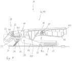
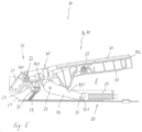
- the movable holding element 22 is movable relative to the fixed holding element 21 for opening and closing the holding recess 23. In an open state of the holding recess 23 (see Fig. 9 ), the movable holding element 22 assumes an open position and vice versa. In a closed state of the retaining recess 23 (see Fig. 4 ), the movable holding element 22 assumes a holding position and vice versa.
- the fixed holding element 21 and/or the movable holding element 22 is made of a plastic material.
- the fixed holding element is made of metal.
- the fixed holding element is preferably provided with a dimensionally flexible and/or elastic insert, via which the mounting section is indirectly supported on the fixed holding element, wherein the insert is made, for example, from a plastic material or the like.
- the dimensionally flexible and/or elastic insert can prevent damage to the mounting section, in particular the plug-in axle, by the metal fixed holding element. If the movable holding element is also made of metal, such an insert can also be provided there.
- the clamping device is designed for the relative movement of the two holding elements and for locking the two holding elements in the holding position.
- the clamping device 30 has a toggle lever mechanism 40 which is operatively connected to the movable holding element 22 and in a movement plane E (drawing plane of the Fig. 4 to 13 ) is movable.
- the toggle lever mechanism 40 serves to move and lock the holding device 20.
- the toggle lever mechanism 40 therefore has an advantageous multiple function. Compared to support units known from the prior art with a separate movement device and a separate locking device, a simplified structure and simplified operation are therefore achieved.
- the holding device 20 is movable in the movement plane E of the toggle lever mechanism 40 between the holding position and the opening position.
- the movement of the holding device takes place in a further Plane of movement which is preferably orthogonal to the plane of movement of the toggle lever mechanism.
- the movable holding element 22 is pivotable relative to the fixed holding element 21 about a first pivot axis S1 between the holding position and the opening position.
- the pivoting movement takes place in the movement plane E of the toggle lever mechanism 40.
- the first pivot axis S1 is orthogonal to the movement plane E.
- the movable holding element 22 is mounted on the fixed holding element 21 by means of the first pivot axis S1.
- the movable holding element 22 is therefore directly connected to/mounted on the fixed holding element 21.
- the movable holding element is mounted on a component and/or section that is firmly connected to the fixed holding element, so that in this case one can also speak of an indirect or indirect fastening of the movable holding element to the fixed holding element.
- a translational mobility is provided instead of or in addition to the pivoting mobility of the movable holding element.
- the movable holding element is movable in a translational manner between the holding position and the opening position by means of the clamping device, more precisely: the toggle lever mechanism, for example parallel or orthogonal to the longitudinal direction of the support rail.
- the movable holding element 22 can be pivoted by approximately 90° by means of the toggle lever mechanism 40 (cf. Fig. 4 and 9 ).
- the movable holding element In the open position ( Fig. 9 ), the movable holding element is pivoted by approximately 90° about the first pivot axis S1 relative to the holding position (see Fig. 4 ).
- the holding recess 23 is opened wide in the open position. This wide opening allows the mounting section M to be easily inserted into the holding recess 23, whereby the mounting section M is prevented from striking the (open) movable holding element 22.
- the movable holding element can be pivoted further than 90°, for example to between 120° and 160°.
- the movable holding element 22 is pre-tensioned in the direction of the opening position by means of a spring element 24.
- the spring element 24 engages at one end on the movable holding element 22 and is fixed at the other end relative to the fixed holding element 21. In the present case, the spring element 24 is directly attached to the fixed holding element 21.
- the spring element 24 engages the movable holding element 22 in the area of the first pivot axis S1 and causes a torque acting about the first pivot axis S1 on the movable holding element 22. In relation to the plane of the drawing of the Fig. 4 to 13 the torque acts clockwise around the first pivot axis S1. In the open position ( Fig. 9 ) the spring element 24 is relaxed or less tensioned than in the holding position ( Fig. 4 ).
- the toggle lever mechanism 40 has an actuating lever 41 and a support lever 42.
- the actuating lever 41 is mounted on the movable holding element 22 so that it can pivot about a second pivot axis S2 relative to the movable holding element 22.
- the support lever 42 is pivotable about a third pivot axis S3 relative to the fixed holding element 21 and is connected to the fixed holding element 21 (directly or indirectly).
- the actuating lever 41 and the support lever 42 are mounted on one another so that they can pivot about a fourth pivot axis S4 relative to one another.
- the second pivot axis S2, the third pivot axis S3 and the fourth pivot axis S4 are parallel to each other and orthogonal to the plane of motion E.
- the second pivot axis S2 is arranged at one end of the actuating lever 41.
- the third pivot axis S3 is arranged at one end of the support lever 42 and the fourth pivot axis S4 is arranged at the other end of the support lever 42.
- the fourth pivot axis S4 is spaced from the second pivot axis S2.
- the actuating lever 41 is longitudinally extended between a first end 411 and a second end 412.
- the actuating lever 41 is longitudinally extended essentially straight.
- the first end 411 faces the holding device 20 and is pivotally mounted on the movable holding element 22 by means of the second pivot axis S2.
- the second pivot axis S2 is arranged in the region of the first end 411 on the actuating lever 41.
- the second end 412 faces away from the holding device 20.
- the support lever 42 is longitudinally extended between a first end 421 and a second end 422.
- the first end 421 faces the holding device 20 and the second end 422 faces away from the holding device 20.
- the fourth Pivot axis S4 is arranged in the region of the first end 421 on the support lever 42.
- the first end 421 is pivotally mounted on the actuating lever 41 by means of the fourth pivot axis S4.
- the fourth pivot axis S4 lies with respect to the actuating lever 41 between its first end 411 and its second end 412.
- the third pivot axis S3 is arranged in the region of the second end 422 on the support lever 42.
- the second end 422 of the support lever 42 is pivotally connected (directly or indirectly) to the fixed holding element 21 by means of the third pivot axis S3.
- the operating lever 41 is moved from the position shown in Fig. 9 shown configuration clockwise about the second pivot axis S2.
- the actuating lever 41 projects predominantly vertically upwards in the open position.
- the support lever 42 moves anti-clockwise about the third pivot axis S3.
- the actuating lever 41 moves clockwise and the support lever 42 moves anti-clockwise.
- the movable holding element 22 is simultaneously pivoted anti-clockwise about the first pivot axis S1.
- the operating lever 41 and the support lever 42 are predominantly aligned horizontally.
- the toggle lever mechanism 40 In the holding position ( Fig. 4 ) the toggle lever mechanism 40 is overextended.
- the overextension of the toggle lever mechanism 40 causes the holding device 20, more precisely: the movable holding element 22, to be locked in the holding position.
- Overextended means that the toggle lever mechanism 40 is moved from the open position in the direction of the holding position past a dead center.
- the dead center can be understood as the configuration of the toggle lever mechanism 40 in which a further movement of the actuating lever 41 in the direction of the holding position does not cause a further movement of the movable holding element 22 in the direction of the holding position.
- the dead center is reached when the second pivot axis S2, the third pivot axis S3 and the fourth pivot axis S4 lie on a straight line within the plane of movement E.
- the first pivot axis S1 When opening and closing the holding recess 23, the first pivot axis S1 always remains stationary within the movement plane E.
- the second pivot axis S2 and the fourth pivot axis S4 can be displaced within the movement plane E.
- the second pivot axis S2 moves on a circular arc-shaped movement path around the first pivot axis S1.
- the fourth pivot axis S4 moves on a circular arc-shaped movement path around the third pivot axis S3.
- the third pivot axis S3 can also be displaced (if necessary) within the plane of movement E. This is described in more detail below. In an embodiment not shown in the figures, the third pivot axis is always stationary in relation to the plane of movement.
- the compensation device 50 is present.
- the compensation device 50 enables the third pivot axis S3 to be displaced within the plane of movement E.
- the compensation device 50 provides limited translational elastic support for the toggle lever mechanism 40 relative to the fixed holding element 21 in the plane of movement E.
- This elastic support causes a size compensation, which enables the movable holding element 22 to be locked in order to hold assembly sections M1, M2 of different sizes in holding positions H1, H2 that are closed to different degrees (see Fig. 12 , 13 ).
- the assembly sections M1, M2 of different sizes can also be referred to as the first assembly section M1 and the second assembly section M2, so that a first holding position H1 ( Fig. 12 ) and a second holding position H2 ( Fig. 13 ).
- the first assembly section M1 is larger than the second assembly section M2.
- the holding recess 23 is closed to a lesser extent than in the second holding position H2. Irrespective of this, the holding device 20 is closed and locked in both the first holding position H1 and the second holding position H2 by means of the toggle lever mechanism 40.
- the compensation device 50 enables the toggle lever mechanism 40 to be overextended both in the first holding position H1 and in the second holding position H2. This is shown in the Fig. 12 and 13
- the fourth swivel axis S4 is in the first holding position H1 and in the second holding position H2 each via the said imaginary connecting line between the second pivot axis S2 and the third pivot axis S3 (overextension).
- the compensating device 50 has at least one compensating spring 51.
- two compensating springs are provided, although only one/the compensating spring 51 is visible in the figures.
- the compensating spring 51 engages at one end on the toggle lever mechanism 40 and is firmly supported at the other end relative to the fixed holding element 21.
- the compensating spring 51 is elastically movable in the plane of movement E.
- the compensating spring 51 is a helical spring.
- the compensating spring 51 is oriented essentially horizontally within the plane of movement E. In the holding position ( Fig. 4 , 12 , 13 ), the support lever 42 and the retaining spring 51 are essentially longitudinally extended parallel.
- the compensating spring is longitudinally extended at an incline starting from the said horizontal orientation.
- the compensating spring is inclined upwards in the direction of the second end of the support lever.
- the inclination can be up to 20°.
- the toggle lever mechanism 40 is supported on the compensation device 50 via the support lever 42.
- the second end 422 of the support lever 42 is attached to the compensation device 50 via the third pivot axis S3 and is thus elastically supported in relation to the fixed holding element 21.
- This elastic support enables a translatory compensation movement of the third pivot axis S3 within the movement plane E.
- the third pivot axis S3 is guided on a guide groove 211 in the embodiment shown (see Fig. 2 ).
- the guide groove 211 is formed in the present case on the fixed holding element 21 and extends horizontally.
- the third swivel axis S3 assumes a first position within the movement plane E (without reference symbol).
- the third pivot axis S3 assumes a second position. In the first position, the third pivot axis S3 is further away from the holding recess 23 than in the second position.
- the compensating spring 51 is more compressed in the first holding position H1 than in the second holding position H2.
- the toggle lever mechanism 40 also has a fixing lever 43.
- the fixing lever 43 is mounted on the actuating lever 41 so that it can pivot about a fifth pivot axis S5 relative to the actuating lever 41.
- the fifth pivot axis S5 is orthogonal to the plane of movement E, so that the fixing lever 43 can pivot within the plane of movement E.
- the fixing lever 43 has a stop section 431. In the holding position ( Fig. 4 , 12 , 13 ), the stop section 431 presses on the support lever 42. This fixes the mobility of the toggle lever mechanism 40. This fixation prevents the toggle lever mechanism 40 from being inadvertently displaced in the direction of the open position, i.e. unlocked.
- the contact with the stop section 431 prevents the support lever 42 from pivoting in a clockwise direction about the third pivot axis S3.
- the stop section 431 can be lifted off the support lever 42. This lifting of the stop section 431 takes place by means of a counterclockwise pivoting movement of the fixing lever 43 about the fifth pivot axis S5.
- the stop portion 431 presses on the support lever 42 between the first end 421 and the second end 422. This contact causes a torque (bending moment) directed counterclockwise about the third pivot axis S3 and clockwise about the fourth pivot axis S4 on the support lever 42.
- the tensioning device 30 also has a lockable lock 60.
- the lock 60 is arranged on the actuating lever 41 and interacts with the support lever 42 in a locked state. By locking the lock in the holding position, the actuating lever 41 and the support lever 42 are releasably connected to one another by means of the lock 60. In the locked state, the lock 60 blocks the mobility of the toggle lever mechanism 40.
- the lockable lock 60 can prevent unauthorized opening of the holding device 20 and thus theft of the bicycle F.
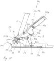
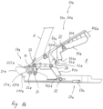
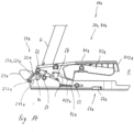
- FIG. 14 to 17 A further embodiment of a support unit 10a according to the invention is shown.
- the support unit 10a according to the Fig. 14 to 17 In terms of its design and function, it is essentially identical to the support unit 10 according to the Fig. 2 to 13 . In order to avoid repetition, the following will therefore primarily focus on the essential differences between the support unit 10a and the support unit 10.
- Components and/or sections with the same function are designated with identical reference numbers plus the lowercase letter "a".
- the support unit 10a points to the Fig. 14 to 17 a further defined position of the holding device 20a and thus also of the clamping device 30a and the toggle lever mechanism 40a.
- This defined position is referred to as the rest position and is in Fig. 16
- the movable holding element 22a is, starting from the open position (see Fig. 14 , 15 ) into the rest position. In the rest position, the holding receptacle 23a is at least partially and/or less wide than in the holding position (see Fig. 17 ) is closed.
- the toggle lever mechanism 40a is releasably locked in the rest position by means of a locking device 70a against an unwanted displacement of the movable holding element 22a in the direction of the open position.
- the rest position can alternatively be referred to as the (pre-)fixing position and is used for temporary, secure pre-fixing of the bicycle F to be secured.
- the mounting section M In the rest position, the mounting section M is held securely in the holding device 20a, although the rest position is not used for permanent fastening and use when the vehicle is in motion (no transport fastening).
- the rest position allows for a simplified and particularly secure fastening process, since the mounting section M is pre-fixed before the holding position is reached, namely in the rest position. This pre-fixing prevents the bicycle F from tipping over during fastening before the holding position is reached, for example due to carelessness on the part of the operator, and causing damage or injuries.
- the movable holding element 22a can be displaced from the open position into the rest position under the influence of the weight of the bicycle fork G to be held. Consequently, no additional action by the operator is required to effect a displacement into the rest position.
- the effect of the bicycle fork G alone, or more precisely: its weight, on the movable holding element 22a is sufficient.
- the movable holding element 22a is pivoted counterclockwise about the first pivot axis S1 into the rest position by means of the mounting section M under the influence of the weight of the bicycle fork G ( Fig. 16 ).
- a sufficiently smooth movement for this purpose can be achieved, for example, by appropriately dimensioning the lever ratios of the toggle lever mechanism 40a.
- the holding receptacle 23a is also formed in the support unit 10a between the movable holding element 22a and the fixed holding element 21a.
- the holding position Fig. 17
- the mounting section M is held in the holding receptacle 23a and thus between the fixed holding element 21a and the movable holding element 22a.
- the rest position Fig. 16
- the holding receptacle 23a is noticeably less closed in the rest position than in the holding position.
- the toggle lever mechanism 40a is not overstretched in the rest position, unlike in the holding position. Rather, the kinematic configuration of the toggle lever mechanism 40a in the rest position is only slightly different from the kinematic configuration in the open position.
- the latter has a receiving recess 221a in the embodiment shown.
- the receiving recess 221a is groove-shaped in cross section and surrounds the mounting section M in the circumferential direction. In the open position, the receiving recess 221a is aligned horizontally forwards and vertically upwards, so that the mounting section M can be inserted into the receiving recess 221a from front to back and from top to bottom.
- the receiving recess 221a ensures that the weight of the bicycle fork G can move the movable holding element 22a about the first pivot axis S1 in the direction of the rest position.
- a force application point of the weight lies within the receiving recess 221a at a distance of one horizontal lever arm from the first pivot axis S1.
- This lever arm causes the movable holding element 22a to be pressed counterclockwise about the first pivot axis S1 under the influence of the weight of the bicycle fork G.
- the locking device 70a has a first locking section 71a and a second locking section 72a.
- the first locking section 71a and the second locking section 72a interact in a form-fitting manner in the direction of the open position.
- the first locking portion 71a is fixedly connected to the fixing lever 43a and is movable together therewith.
- the first locking portion 71a is an integral portion of the fixing lever 43a.
- the second locking portion 72a is fixedly connected to the support lever 42a and is movable together therewith.
- the second locking portion 72a is an integral portion of the support lever 42a.
- the first locking section 71a is arranged in the area of the stop section 431a.
- the first locking section 71a is designed in the form of a hook.
- the second locking section 72a is designed in the form of an undercut complementary to the hook.
- the first locking section 71a engages behind the second locking section 72a in the rest position. This engagement behind prevents the actuating lever 41a and thus the entire toggle lever mechanism 40a from being inadvertently displaced from the rest position towards the open position.
- the positive connection between the first locking section 71a and the second locking section 72a can be canceled by actuating the fixing lever 43a.
- the fixing lever 43a can be moved from the position shown in Fig. 16 shown configuration can be pivoted counterclockwise about the fifth pivot axis S5 relative to the actuating lever 41a. This removes the positive locking.
- the first locking section 71a extends out from the second locking section 72a.
- a front end 222a of the movable holding element 22a interacts with an abutment 211a.
- the abutment 211a is immovable relative to the fixed holding element 21a.
- the abutment 211a is formed by a section of the fixed holding element 21a.
- the front end 222a When moving in the direction of the holding position, the front end 222a runs against the abutment 211a under friction, in particular tangentially. In the holding position, the friction between the front end 222a and the abutment 211a (additionally) counteracts a movement in the direction of the opening position.
Landscapes
- Engineering & Computer Science (AREA)
- Mechanical Engineering (AREA)
- Fittings On The Vehicle Exterior For Carrying Loads, And Devices For Holding Or Mounting Articles (AREA)
Applications Claiming Priority (1)
| Application Number | Priority Date | Filing Date | Title |
|---|---|---|---|
| PL44552523 | 2023-07-10 |
Publications (1)
| Publication Number | Publication Date |
|---|---|
| EP4491461A1 true EP4491461A1 (fr) | 2025-01-15 |
Family
ID=91899074
Family Applications (1)
| Application Number | Title | Priority Date | Filing Date |
|---|---|---|---|
| EP24187516.0A Pending EP4491461A1 (fr) | 2023-07-10 | 2024-07-09 | Unité de support pour un porte-vélo |
Country Status (1)
| Country | Link |
|---|---|
| EP (1) | EP4491461A1 (fr) |
Citations (4)
| Publication number | Priority date | Publication date | Assignee | Title |
|---|---|---|---|---|
| US20070012738A1 (en) * | 2005-07-12 | 2007-01-18 | Michael Grim | Through-axle bicycle fork mounting clamp |
| US20160023615A1 (en) * | 2014-07-25 | 2016-01-28 | Thule Sweden Ab | Adjustable Anchor On A Load Carrier For A Bicycle Through-Axle |
| EP3590765A1 (fr) * | 2018-07-04 | 2020-01-08 | Thule Sweden AB | Support de vélo |
| EP3838678B1 (fr) | 2019-12-20 | 2022-04-27 | Thule Sweden AB | Unité de support pour support de bicyclette |
-
2024
- 2024-07-09 EP EP24187516.0A patent/EP4491461A1/fr active Pending
Patent Citations (4)
| Publication number | Priority date | Publication date | Assignee | Title |
|---|---|---|---|---|
| US20070012738A1 (en) * | 2005-07-12 | 2007-01-18 | Michael Grim | Through-axle bicycle fork mounting clamp |
| US20160023615A1 (en) * | 2014-07-25 | 2016-01-28 | Thule Sweden Ab | Adjustable Anchor On A Load Carrier For A Bicycle Through-Axle |
| EP3590765A1 (fr) * | 2018-07-04 | 2020-01-08 | Thule Sweden AB | Support de vélo |
| EP3838678B1 (fr) | 2019-12-20 | 2022-04-27 | Thule Sweden AB | Unité de support pour support de bicyclette |
Similar Documents
| Publication | Publication Date | Title |
|---|---|---|
| EP2689964B1 (fr) | Verrouillage de container | |
| EP0311936B1 (fr) | Chariot pour un brancard | |
| EP2279981B1 (fr) | Dispositif de verrouillage pour un bloc de batterie d'un chariot de manutention | |
| EP1359059B1 (fr) | Système d'arceau de sécurité pour véhicules avec un dispositif de deverrouillage autobloquant | |
| DE2450909B2 (de) | Fernbedienungseinrichtung zum öffnen und Schließen einer Seitentür eines Personenkraftwagens | |
| EP1112881A2 (fr) | Dispositif de verrouillage pour toit pliant | |
| DE602005004846T2 (de) | Verriegelungsanordnung für ein Cabriolet-Verdeck | |
| EP1617031A2 (fr) | Porte coulissante pour un véhicule | |
| EP0939005A1 (fr) | Dispositif pour fixer des articles dans le compartiment à bagages d'un véhicule | |
| DE102025134767A1 (de) | Griffanordnung und bewegliches Fahrzeugelement | |
| DE19857322C2 (de) | Dachlastenträgersystem | |
| EP1336530A2 (fr) | Dispositif de fixation pour siège enfant | |
| DE19528308C2 (de) | Fahrzeug, insbesondere Personenkraftwagen | |
| EP2368765B1 (fr) | Support de toit | |
| DE10353242B3 (de) | Fahrzeugsitz | |
| EP4491461A1 (fr) | Unité de support pour un porte-vélo | |
| EP3656610B1 (fr) | Support de chargement à l'arrière | |
| WO2007118505A1 (fr) | SYSTèME DE DéPLACEMENT D'UN SIèGE DE VéHICULE | |
| DE10010056B4 (de) | Druckplattenwechsler | |
| DE10321347B4 (de) | Halterungsvorrichtung für Dachkoffer | |
| DE1940861A1 (de) | Abschliessbarer Skitraeger fuer Kraftfahrzeuge | |
| EP0921029B1 (fr) | Siège de véhicule à dossier rabattable | |
| DE10011545C1 (de) | Kraftfahrzeugsitz mit beidseitig an Adaptern klappbar und neigungsverstellbar gelagerter Rückenlehne | |
| DE102019215763B4 (de) | Heckträgersystem für ein Kraftfahrzeug | |
| EP0075038B1 (fr) | Fermeture de serrage avec espagnolette pour une porte mobile de carrosserie de camions, conteneurs et analogues |
Legal Events
| Date | Code | Title | Description |
|---|---|---|---|
| PUAI | Public reference made under article 153(3) epc to a published international application that has entered the european phase |
Free format text: ORIGINAL CODE: 0009012 |
|
| STAA | Information on the status of an ep patent application or granted ep patent |
Free format text: STATUS: THE APPLICATION HAS BEEN PUBLISHED |
|
| AK | Designated contracting states |
Kind code of ref document: A1 Designated state(s): AL AT BE BG CH CY CZ DE DK EE ES FI FR GB GR HR HU IE IS IT LI LT LU LV MC ME MK MT NL NO PL PT RO RS SE SI SK SM TR |
|
| STAA | Information on the status of an ep patent application or granted ep patent |
Free format text: STATUS: REQUEST FOR EXAMINATION WAS MADE |
|
| 17P | Request for examination filed |
Effective date: 20250709 |