EP4491487A2 - Train de roulement pour un véhicule ferroviaire et véhicule ferroviaire comprenant au moins un train de roulement, véhicule ferroviaire comprenant au moins un wagon de chemin de fer et procédé de réglage en hauteur d'une caisse d'un véhicule ferroviaire - Google Patents
Train de roulement pour un véhicule ferroviaire et véhicule ferroviaire comprenant au moins un train de roulement, véhicule ferroviaire comprenant au moins un wagon de chemin de fer et procédé de réglage en hauteur d'une caisse d'un véhicule ferroviaire Download PDFInfo
- Publication number
- EP4491487A2 EP4491487A2 EP24216752.6A EP24216752A EP4491487A2 EP 4491487 A2 EP4491487 A2 EP 4491487A2 EP 24216752 A EP24216752 A EP 24216752A EP 4491487 A2 EP4491487 A2 EP 4491487A2
- Authority
- EP
- European Patent Office
- Prior art keywords
- chassis
- wheel
- rail vehicle
- rockers
- wheels
- Prior art date
- Legal status (The legal status is an assumption and is not a legal conclusion. Google has not performed a legal analysis and makes no representation as to the accuracy of the status listed.)
- Granted
Links
Images




Classifications
-
- B—PERFORMING OPERATIONS; TRANSPORTING
- B61—RAILWAYS
- B61D—BODY DETAILS OR KINDS OF RAILWAY VEHICLES
- B61D13/00—Tramway vehicles
-
- B—PERFORMING OPERATIONS; TRANSPORTING
- B61—RAILWAYS
- B61C—LOCOMOTIVES; MOTOR RAILCARS
- B61C9/00—Locomotives or motor railcars characterised by the type of transmission system used; Transmission systems specially adapted for locomotives or motor railcars
- B61C9/38—Transmission systems in or for locomotives or motor railcars with electric motor propulsion
- B61C9/48—Transmission systems in or for locomotives or motor railcars with electric motor propulsion with motors supported on vehicle frames and driving axles, e.g. axle or nose suspension
- B61C9/50—Transmission systems in or for locomotives or motor railcars with electric motor propulsion with motors supported on vehicle frames and driving axles, e.g. axle or nose suspension in bogies
-
- B—PERFORMING OPERATIONS; TRANSPORTING
- B61—RAILWAYS
- B61F—RAIL VEHICLE SUSPENSIONS, e.g. UNDERFRAMES, BOGIES OR ARRANGEMENTS OF WHEEL AXLES; RAIL VEHICLES FOR USE ON TRACKS OF DIFFERENT WIDTH; PREVENTING DERAILING OF RAIL VEHICLES; WHEEL GUARDS, OBSTRUCTION REMOVERS OR THE LIKE FOR RAIL VEHICLES
- B61F15/00—Axle-boxes
-
- B—PERFORMING OPERATIONS; TRANSPORTING
- B61—RAILWAYS
- B61F—RAIL VEHICLE SUSPENSIONS, e.g. UNDERFRAMES, BOGIES OR ARRANGEMENTS OF WHEEL AXLES; RAIL VEHICLES FOR USE ON TRACKS OF DIFFERENT WIDTH; PREVENTING DERAILING OF RAIL VEHICLES; WHEEL GUARDS, OBSTRUCTION REMOVERS OR THE LIKE FOR RAIL VEHICLES
- B61F3/00—Types of bogies
- B61F3/02—Types of bogies with more than one axle
- B61F3/04—Types of bogies with more than one axle with driven axles or wheels
-
- B—PERFORMING OPERATIONS; TRANSPORTING
- B61—RAILWAYS
- B61F—RAIL VEHICLE SUSPENSIONS, e.g. UNDERFRAMES, BOGIES OR ARRANGEMENTS OF WHEEL AXLES; RAIL VEHICLES FOR USE ON TRACKS OF DIFFERENT WIDTH; PREVENTING DERAILING OF RAIL VEHICLES; WHEEL GUARDS, OBSTRUCTION REMOVERS OR THE LIKE FOR RAIL VEHICLES
- B61F3/00—Types of bogies
- B61F3/16—Types of bogies with a separate axle for each wheel
-
- B—PERFORMING OPERATIONS; TRANSPORTING
- B61—RAILWAYS
- B61F—RAIL VEHICLE SUSPENSIONS, e.g. UNDERFRAMES, BOGIES OR ARRANGEMENTS OF WHEEL AXLES; RAIL VEHICLES FOR USE ON TRACKS OF DIFFERENT WIDTH; PREVENTING DERAILING OF RAIL VEHICLES; WHEEL GUARDS, OBSTRUCTION REMOVERS OR THE LIKE FOR RAIL VEHICLES
- B61F5/00—Constructional details of bogies; Connections between bogies and vehicle underframes; Arrangements or devices for adjusting or allowing self-adjustment of wheel axles or bogies when rounding curves
- B61F5/02—Arrangements permitting limited transverse relative movements between vehicle underframe or bolster and bogie; Connections between underframes and bogies
- B61F5/22—Guiding of the vehicle underframes with respect to the bogies
-
- B—PERFORMING OPERATIONS; TRANSPORTING
- B61—RAILWAYS
- B61F—RAIL VEHICLE SUSPENSIONS, e.g. UNDERFRAMES, BOGIES OR ARRANGEMENTS OF WHEEL AXLES; RAIL VEHICLES FOR USE ON TRACKS OF DIFFERENT WIDTH; PREVENTING DERAILING OF RAIL VEHICLES; WHEEL GUARDS, OBSTRUCTION REMOVERS OR THE LIKE FOR RAIL VEHICLES
- B61F5/00—Constructional details of bogies; Connections between bogies and vehicle underframes; Arrangements or devices for adjusting or allowing self-adjustment of wheel axles or bogies when rounding curves
- B61F5/02—Arrangements permitting limited transverse relative movements between vehicle underframe or bolster and bogie; Connections between underframes and bogies
- B61F5/22—Guiding of the vehicle underframes with respect to the bogies
- B61F5/24—Means for damping or minimising the canting, skewing, pitching, or plunging movements of the underframes
-
- B—PERFORMING OPERATIONS; TRANSPORTING
- B61—RAILWAYS
- B61F—RAIL VEHICLE SUSPENSIONS, e.g. UNDERFRAMES, BOGIES OR ARRANGEMENTS OF WHEEL AXLES; RAIL VEHICLES FOR USE ON TRACKS OF DIFFERENT WIDTH; PREVENTING DERAILING OF RAIL VEHICLES; WHEEL GUARDS, OBSTRUCTION REMOVERS OR THE LIKE FOR RAIL VEHICLES
- B61F5/00—Constructional details of bogies; Connections between bogies and vehicle underframes; Arrangements or devices for adjusting or allowing self-adjustment of wheel axles or bogies when rounding curves
- B61F5/26—Mounting or securing axle-boxes in vehicle or bogie underframes
- B61F5/30—Axle-boxes mounted for movement under spring control in vehicle or bogie underframes
- B61F5/301—Axle-boxes mounted for movement under spring control in vehicle or bogie underframes incorporating metal springs
- B61F5/304—Torsion-bar springs
-
- B—PERFORMING OPERATIONS; TRANSPORTING
- B61—RAILWAYS
- B61F—RAIL VEHICLE SUSPENSIONS, e.g. UNDERFRAMES, BOGIES OR ARRANGEMENTS OF WHEEL AXLES; RAIL VEHICLES FOR USE ON TRACKS OF DIFFERENT WIDTH; PREVENTING DERAILING OF RAIL VEHICLES; WHEEL GUARDS, OBSTRUCTION REMOVERS OR THE LIKE FOR RAIL VEHICLES
- B61F5/00—Constructional details of bogies; Connections between bogies and vehicle underframes; Arrangements or devices for adjusting or allowing self-adjustment of wheel axles or bogies when rounding curves
- B61F5/50—Other details
-
- B—PERFORMING OPERATIONS; TRANSPORTING
- B61—RAILWAYS
- B61F—RAIL VEHICLE SUSPENSIONS, e.g. UNDERFRAMES, BOGIES OR ARRANGEMENTS OF WHEEL AXLES; RAIL VEHICLES FOR USE ON TRACKS OF DIFFERENT WIDTH; PREVENTING DERAILING OF RAIL VEHICLES; WHEEL GUARDS, OBSTRUCTION REMOVERS OR THE LIKE FOR RAIL VEHICLES
- B61F5/00—Constructional details of bogies; Connections between bogies and vehicle underframes; Arrangements or devices for adjusting or allowing self-adjustment of wheel axles or bogies when rounding curves
- B61F5/50—Other details
- B61F5/52—Bogie frames
-
- Y—GENERAL TAGGING OF NEW TECHNOLOGICAL DEVELOPMENTS; GENERAL TAGGING OF CROSS-SECTIONAL TECHNOLOGIES SPANNING OVER SEVERAL SECTIONS OF THE IPC; TECHNICAL SUBJECTS COVERED BY FORMER USPC CROSS-REFERENCE ART COLLECTIONS [XRACs] AND DIGESTS
- Y02—TECHNOLOGIES OR APPLICATIONS FOR MITIGATION OR ADAPTATION AGAINST CLIMATE CHANGE
- Y02T—CLIMATE CHANGE MITIGATION TECHNOLOGIES RELATED TO TRANSPORTATION
- Y02T30/00—Transportation of goods or passengers via railways, e.g. energy recovery or reducing air resistance
Definitions
- the present invention relates to a chassis for a rail vehicle, as well as a rail vehicle carriage with at least one chassis, a rail vehicle with at least one rail vehicle carriage and a method for adjusting the height of a carriage body.
- the chassis of rail vehicles support one or more pairs of wheels opposite the car body.
- the term chassis covers rotating bogies, in which pairs of wheels are supported in a frame that rotates opposite the car body, and non-rotating chassis that are attached to the car body. Chassis for low-floor rail vehicles pose particular challenges: due to the low floor height within the car body, the chassis must not exceed a certain height, particularly in the area between the wheels.
- the DE 26 16 923 reveals a torsion bar suspension system that is supported by freely sliding lever arms of different lengths.
- the system is very susceptible to failure and unstable.
- powered chassis in particular do not allow for a continuous, wide low-floor area because the available installation space in the area of the car body is limited.
- torsion bars are directly fixed to the chassis frame, high forces and moments are introduced directly into the frame, so that the frame must be correspondingly stable and therefore complex and heavy.
- the object of the present invention is to remedy these and other disadvantages of the prior art and in particular to provide a simple and stable chassis that enables a continuous low-floor area and a large aisle width, especially above a motorized chassis, and can be flexibly adapted to different track widths and areas of use.
- the chassis should also be able to be used as a running chassis with largely the same basic concept without any significant cost and functional disadvantages.
- a chassis for a rail vehicle as well as a rail vehicle carriage with at least one chassis, a rail vehicle with at least one rail vehicle carriage and in methods for adjusting the height of a car body of a rail vehicle carriage according to the independent claims.
- Such a chassis enables a continuous or essentially continuous low-floor area as well as a wide aisle width in the chassis area. Simple suspension is also possible.
- the connection of the torsion bars leads to balanced wheel loads even when driving over uneven surfaces. This increases derailment safety and reduces structural loads on the chassis frame.
- the connecting elements are preferably not rigidly connected to the chassis frame, in particular they are not part of the chassis frame. This means that the torques are not introduced into the chassis frame or are only introduced to a small extent.
- the chassis frame is designed as a substantially box-shaped component and can be divided into different compartments by partition walls. Some or all of the compartments can have a floor. The compartments can have openings.
- axle is understood here to mean a rotating or non-rotating physical device that extends in a longitudinal direction for attaching the wheels.
- a geometric axis is the ideal axis of rotation of an object.
- Wheels can have a rotating wheel axle (in the case of independent wheel suspension, only a very short one) with which they are mounted on other components.
- stationary (non-rotating) wheel axles are also possible, especially with independent wheel suspensions.
- wheel bearing refers to the bearing between the wheel axle and the component that supports it; in the case of stationary axles, the term is to be interpreted accordingly and usually refers to the bearing between the rotating wheel and the stationary axle.
- Wheel axles can be designed in several parts and carry one or two wheels.
- a wheel pair is defined as two wheels with essentially aligned geometric wheel axles, for example the two wheels arranged at the front or rear of the chassis in the direction of travel.
- the wheel suspensions can be designed as wheel sets, portal or independent wheel axles or as independent wheel suspensions.
- a wheel set is a device in which the two wheels are attached to a common wheel axle in a rotationally fixed manner.
- An independent wheel or portal axle is a wheel axle in which the wheels are mounted on a non-rotating structure.
- portal axles are all axle variants with a non-coaxial cross connection, for example cranked portal axles. This makes it possible to have a lower floor in the area of the axle.
- the wheel axles of the wheels are mounted on both sides in the non-rotating structure. Alternatively, the wheels can also be mounted directly on the non-rotating structure without their own wheel axle. With an independent wheel suspension, each wheel also has its own wheel axle, but these are not directly connected to one another.
- the landing gear can include at least one motor to drive the landing gear. This makes it easy to drive the landing gear.
- the connecting element can be made of high-strength material such as tempered steel, e.g. 34CrMo4. Such a material has a particularly high level of strength.
- the connecting element can be forged. This makes a space-saving solution possible.
- the chassis can be designed for narrow gauge, standard gauge, broad gauge or meter gauge. This allows the chassis to be used in a wide range of applications while retaining the same components, in particular the same chassis frame.
- the chassis comprises four swing arms. Each swing arm is mounted on the chassis frame via a torsion bar, preferably exclusively via a torsion bar.
- the wheel axle is mounted on the swing arms via the wheel bearing.
- the geometric axes of the torsion bars are arranged essentially parallel to the wheel axles. This allows for simple arrangement of the torsion bars and simple torque transmission.
- the torsion bars are mounted on the chassis frame in a movable manner, in particular with an elastic bearing.
- the torsion bars are mounted in such a way that they can be displaced along the geometric bar axis by essentially +/- 5 mm.
- the object is further achieved by a chassis for a rail vehicle, in particular a chassis as described above.
- the chassis comprises a chassis frame, at least one, preferably two, portal axles and at least one damping system for damping movements between the chassis frame and the wheel axle.
- the damping system comprises at least one damping element and at least one, preferably two, motion transmission elements for transmitting a vertical deflection movement of the chassis frame.
- the motion transmission element is arranged with one end at a motion transmission point on the portal axle.
- the damping element is arranged between the portal axle and the chassis frame and with one end on the portal axle at a damping connection point.
- the damping element is arranged in particular so that the damping direction is parallel to the direction of travel.
- the portal axle is designed to be pivotable in the direction away from the chassis frame. A distance between the damping connection point and the geometric wheel axis is greater than the distance between the motion transmission point and the geometric wheel axis.
- Such a damping system has a low overall height and thus allows a simple construction of a low-floor chassis.
- Such a damping system also enables a simple increase in the damping stroke, which can be adapted to the compression of the primary suspension:
- the portal axle is deflected so that the distance between the chassis frame and the portal axle is increased.
- the stroke length of the damping element and thus the spring travel increases accordingly.
- each portal axle comprises two side parts and a bridge support arranged between the side parts, wherein the side parts and bridge supports are arranged between the wheels.
- Each side part comprises a portal axle bearing.
- At least one motion transmission element is arranged on a side part at a motion transmission distance from the geometric axis of the portal axle bearing, so that the bridge support can be rotated about the geometric axis of the portal axle bearing when the chassis frame is deflected vertically.
- the damping element therefore has a stroke increased by a factor when the primary suspension is compressed by z.
- the factor depends on the selected geometry.
- the damping element can be arranged on the bridge girder.
- the chassis preferably comprises at least two support elements for direct connection to a car body.
- the support elements comprise in particular curved guides, slewing ring segments, preferably with sliding elements, and/or rollers, in particular cylindrical or tapered rollers.
- the support elements can have a support plane for contact with a corresponding segment on the car body. This enables a simple connection to the car body.
- the slewing ring segments can be equipped with bearings with rolling elements, preferably rotating rolling elements.
- rolling elements preferably rotating rolling elements.
- curved guides are very demanding in terms of correct support conditions - similar to bearings.
- Even small geometric deviations between the support planes or radius deviations of the segments lead to impermissible cardanic and/or transverse loads on the guides due to the high rigidity of the components and the tolerance deviations that occur in vehicle construction.
- Elastic elements can therefore be formed between the support element and the chassis. These are designed in such a way that they can withstand the loads that occur during operation (vertical load, transverse load, etc.) and only generate small cardanic moments in the event of angular deviations of the support planes. The same applies to any transverse deviations.
- the rollers are preferably mounted in a structure arranged above a secondary suspension in the chassis frame so that a car body can roll on the rollers.
- Such a chassis has a very low overall height and thus leads to a simple construction of a rail vehicle and a simple flow of force via the support elements.
- the chassis preferably comprises a secondary suspension.
- This secondary suspension comprises in particular a coil spring, an air spring and/or a rubber spring. This improves driving comfort.
- the chassis preferably comprises at least two, preferably four, spring elements for anti-roll reinforcement, in particular anti-roll springs.
- the spring elements are particularly preferably arranged between the chassis frame and the connecting elements, so that the chassis frame is at least partially supported on the connecting elements. The arrangement of the spring elements means that anti-roll reinforcement can be implemented in a simple manner via the primary suspension.
- Rolling is generally understood to mean a lateral tilting of the car body in relation to the direction of travel.
- the swaying car body is supported by the secondary suspension on the chassis frame. This causes the chassis frame to tilt and the spring elements at least partially absorb the movement of the car body.
- the spring elements preferably comprise elastomers such as chloroprene or other plastics such as polyurethane. This allows for a cost-effective yet stable suspension.
- the spring elements can comprise metal inserts.
- the spring elements can be progressive and/or have a gap for free play. This increases driving comfort, as the spring effect is relatively soft when the force is applied and/or the spring elements only compress after a certain inclination of the chassis. Under high loads, the spring effect is still hard.
- the spring elements are preferably arranged in the middle of the connecting element. If the car body tilts to one side, the spring elements arranged below the connecting element are loaded on the side that is tilting, while those on the side that is lifting are relieved. This creates a restoring force that counteracts the rolling.
- stiffening against pitching movements can also be achieved if required.
- Pitching movements are tilting movements of the car body in the direction of travel.
- the chassis comprises a chassis frame, four wheels, each with a wheel bearing, and four rockers. At least one rocker, preferably two, particularly preferably four, rockers, connects a wheel axle to a drive axle.
- the wheels each comprise an inner and an outer side.
- the chassis comprises an inner area between the inner sides of the wheels and an outer area outside the inner side of the wheels.
- the rockers are each arranged in the outer area of the chassis.
- Each wheel is mounted via a wheel axle in at least one wheel bearing. At least one wheel bearing is arranged in or on the respective rocker and at least one wheel bearing is simultaneously the transmission bearing.
- the wheels can be mounted exclusively via the swing arms. This allows for a simple and compact design of the chassis.
- a wheel bearing can include one or more rolling bearings. This allows for easy mounting of the wheels.
- a swing arm forms at least part of the connection between a wheel and the chassis frame and is movable relative to the frame.
- the wheel suspensions can be designed as wheel sets, portal or independent wheel axles or as independent wheel suspension.
- a wheel set allows two wheels to be driven in a simple manner with one motor and one transmission.
- Independent wheel axles allow the use of independent wheel drives.
- Portal axles enable a simple and compact design of the chassis and a rail vehicle with a continuous or essentially continuous low-floor floor. Such a chassis also enables large aisle widths in the chassis area.
- the wheels are each supported exclusively by a swing arm and a torsion bar and are preferably connected by portal axles.
- the chassis preferably comprises at least one, preferably two, particularly preferably four, gears.
- Each gear is arranged on a swing arm, preferably integrated into the swing arm. This allows a space-saving design.
- the gear can be mounted on the swing arm. If the gear is integrated into the swing arm, the swing arm essentially also serves as the gear housing. This arrangement therefore saves material and weight.
- the chassis preferably comprises adjustment means for adjusting the distance between the wheel axle and the chassis frame.
- the adjustment means preferably allow the position of the rockers relative to the chassis frame to be changed, in particular increased or decreased.
- the rockers are made of two parts and the position of a first part can be changed relative to a second part.
- the first part comprises the bearing connected to the chassis frame, the second part the bearing connected to the wheel.
- the parts are provided with fixing and/or locking elements.
- the fixing elements can comprise slots and/or screws.
- the locking elements can comprise interchangeable molded parts.
- the locking elements have fastening positions. The fastening positions allow the positions of the swing arms to be changed discretely, in particular so that a vertical distance between the wheel axles and the chassis frame can be changed by 10 mm each. is changeable.
- the locking elements can include slots and/or screws. These locking elements are designed in such a way that the position of the swing arm axis can be adjusted in relation to the wheel axis.
- the position of the torsion bars can be adjusted using the adjustment means.
- the angular position of the torsion bars relative to the chassis frame can be adjusted.
- the angular position of the torsion bars relative to the connecting element can be adjusted. This makes the structure of the adjustment device simple and effective.
- At least one connecting element comprises a bridge and adjusting means.
- the adjusting means comprise at least two levers, wherein the support point of the levers on the bridge can be displaced in the vertical direction in order to adjust the angular position of the torsion bars.
- the support point can be displaced by rotating at least one eccentric connected to the levers.
- the adjustment means can therefore comprise eccentrics and two levers.
- the eccentrics and a lever each connected to a torsion bar in a rotationally fixed manner can be arranged on the bridge.
- the torsion bars can be rotatably mounted in the bridge.
- the adjustment device ultimately serves to easily change the height of the car body above the top edge of the rail (SOK): If the eccentric is turned, the levers are moved and the angular positions of the torsion bars are changed in relation to each other and in relation to the chassis frame. All torques are absorbed by the levers. This changes the position of the rockers and thus the height of the car body support above the SOK.
- the chassis preferably comprises at least one, in particular two, stiffening elements, in particular hollow beams, for stiffening against a rotational movement of the rockers. Each rocker comprises an extension element for extending the rocker.
- the extension elements of the rockers on one chassis side are each connected or can be connected via a stiffening element, so that the rotational movements of the rockers about the geometric wheel axes can be at least partially cushioned.
- the connections between the stiffening element and the rockers each comprise a distance, so that the rotational movements of the rockers about the geometric wheel axes can only be cushioned by the stiffening element once the chassis has reached a predetermined load.
- the load on the chassis refers to the forces that act on a chassis when a vehicle is loaded, so that the primary suspension is shifted by a vertical spring travel.
- the rockers rotate slightly; only the primary suspension is effective. From a certain load on the chassis, the rotational movements of the rockers become so large that the distance is overcome and the stiffening element cushions the rotational movements.
- the extension element can be a part of a swing arm, in particular the swing arm housing or the gearbox mount, or an element attached to the swing arm.
- a progressive suspension i.e. a soft suspension at low loads and a a hard suspension.
- a soft suspension at low loads and a hard suspension.
- a relatively high level of comfort is achieved thanks to the soft spring.
- hard suspension prevents excessive spring travel.
- rubber angle springs such as chevron springs or additional spring elements such as buffers can be used, which come into effect above a defined spring travel.
- One or more spring elements can be arranged in the space between the stiffening element and the swing arm. This makes it easy to achieve the desired suspension.
- the stiffening element can be connected and/or connectable to an extension element via a support element and/or a supporting element.
- the support element and/or the supporting element comprises an elastomeric material, in particular polyurethane.
- the stiffening elements each comprise at least one support element for resting on an extension element and a support element for supporting an extension element.
- at least one extension element is connected to the stiffening element via the support element and the support element.
- each stiffening element is arranged on the extension elements in such a way that, in the case of a load that is less than the predetermined load, the stiffening element rests on the extension elements and, in the case of a load that corresponds to or is greater than the predetermined load, there is a second contact point between the stiffening element and each extension element so that the extension elements are wedged in the stiffening element.
- the stiffening element can be designed as a hollow body, in particular tubular, preferably with a rectangular cross-section. In the event of a crash, the stiffening element can be at least partially plastically deformable. On the other hand, dynamically caused force peaks are mitigated in the event of a crash and limited to the amount corresponding to the yield strength of the material used.
- the chassis preferably comprises at least one, preferably two, particularly preferably four, motors.
- the motor(s) are arranged in the interior, and the motor(s) preferably each comprise a drive shaft which is arranged parallel to the wheel axle.
- Each motor drives at least one wheel via a gearbox, whereby each wheel can be mounted on a swing arm.
- the gearbox can be designed as a spur gear. Spur gears have a simple design, are robust and have a high level of efficiency.
- the motors are arranged on the outer surfaces of the chassis frame and/or attached to the outer surfaces of the chassis frame. This enables a compact design of the chassis.
- Narrow-gauge railways are so easy to build and still have sufficient power from powered running gear.
- Each motor is preferably connected to the transmission input shaft via at least one compensating coupling.
- the compensating coupling is designed in particular in such a way that a radial axis offset is possible:
- the transmission output axis is also the wheel axis.
- the corresponding transmission bearing serves as a wheel bearing. This enables a simple and space-saving construction of a driven chassis, since fewer support elements have to be used for the bearing of wheels and transmission and a low-floor area above the interior of the chassis is also possible with driven chassis.
- the wheel axle can be designed in several parts, in particular comprising an adapter screwed onto the wheel.
- each motor in particular the motor housing, has a cross-sectional diameter of less than 200mm.
- the cross-sectional diameter refers to the diameter of the entire motor including the housing.
- each motor has an output of between 45 and 60 kW.
- the motors can have speeds of 10-12kU/min. Such motors enable a chassis structure with a low height in which the motors are arranged under the low-floor area and thus a simple construction of low-floor rail vehicles.
- two motors can be connected or are connected to a clutch.
- two motors can be connected or are connected to a detachable or rigid clutch, preferably to a passive clutch, particularly preferably to a centrifugal clutch.
- two motors are arranged in such a way that their shafts can be connected between the motors and are each coupled to a wheel via the swing arm on the side opposite the connection.
- two motors assigned to a wheel pair can be coupled.
- the motor axes of the motors to be coupled are aligned.
- a rigid coupling of the motors enables sinusoidal running, but leads to high torques in the drive train when driving around tight bends and to increased wheel slip.
- the passive clutch preferably works in such a way that it releases at low speeds and thus enables cornering without constraints. At high speeds the clutch closes and thus straight-line running is improved. However, the clutch allows slipping when there are large torque differences.
- a centrifugal force-based slip clutch for example, can therefore be considered as a clutch.
- the clutches can be implemented separately as independent clutches or as a single unit.
- the object is further achieved by a chassis for a rail vehicle according to claim 10.
- the chassis comprises at least one, preferably two magnetic rail brakes.
- the magnetic rail brake is attached to the swing arm via a cable pull.
- Magnetic rail brakes on tram vehicles are usually held approximately 10 mm above the top edge of the rail (SOK) using pre-tensioned springs. This distance must be maintained under all operating conditions - for example, when the vehicle is compressing or rebounding. On the one hand, this is to prevent the brake shoe from dragging on the rails when the vehicle is not braking. On the other hand, the distance to the rail should be small: if the distance between the brake shoe and the rail is too great, the magnetic field generated is not sufficient to overcome the spring forces. The force of the pre-tensioned suspension springs must also be overcome.
- the brake shoes are attached to a bracket connected to the two axle bearing housings so that the compression and rebound travel of the chassis frame has no influence on the distance between the brake shoe and the rail.
- the magnetic rail brake preferably comprises a brake shoe, a cable and a deflection pulley.
- the cable is attached to a frame attachment point of the chassis frame and to a brake attachment point of the brake shoe.
- the cable is guided over the deflection pulley between the frame attachment point and the brake attachment point.
- the deflection roller can be attached to a swing arm at a horizontal distance c from the geometric swing arm axis.
- the horizontal distance c can be approximately 2/3 of the horizontal distance a between the geometric swing arm axis and the wheel axis.
- the cable can have a first cable section and a second cable section.
- the first cable section can be arranged between the brake attachment point and the pulley.
- the first cable section can be arranged substantially vertically.
- the second cable section can be arranged between the pulley and the frame attachment point at an angle ⁇ of substantially 60° to the vertical.
- the magnetic rail brakes can be attached in a space-saving and simple manner: With this suitable choice of the geometry of the deflection, in particular the position of the deflection roller on the swing arm, the frame attachment point and the brake attachment point, the deflection of the primary suspension can be easily compensated and a constant distance between the rail and the magnetic rail brake can be easily maintained: the swing arm changes its position slightly, whereby the height of the magnetic rail brake above the rail is adjusted via the cable pull.
- the distances a and c and the angle ⁇ are preferably selected so that when the frame attachment point is shifted vertically by a frame shift z, the vertical distance between the wheel axle and the brake attachment point does not change or only changes slightly.
- the chassis can comprise at least one wheel set with a track width W.
- Each wheel comprises a running surface on its circumference.
- the wheels of a wheel set are arranged in particular on a standard track axle.
- the wheels of a wheel set are each arranged at an average fastening distance from one another.
- the average fastening distance is in particular between 1200mm and 1600mm, in particular essentially 1540mm.
- the running surfaces of the wheels are offset from the inner area to the outside in such a way that the track width is at least 20mm, in particular at least 42mm, larger than the average fastening distance.
- the track width is preferably between 1400mm and 1676mm so that the chassis can be used for a broad gauge railway.
- the wheels have an inner wheel side, an outer wheel side, wheel flanges and wheel hubs.
- a wheel for a rail vehicle comprises a tread and a wheel flange as well as two wheel sides.
- the wheel side closest to the wheel flange is the inner wheel side.
- the wheel side closest to the tread is the outer wheel side.
- the wheel faces and the wheel hub planes are arranged on the wheel sides.
- the wheel hubs are extended along the geometric wheel axes from the inside of the wheel to the outside of the wheel.
- the wheel hub thus comprises an inner wheel hub plane and an outer wheel hub plane.
- the distance from the centre point between the inner and outer wheel hub planes of a first wheel to the centre point between the inner and outer wheel hub planes of a second wheel is the mean mounting distance.
- the distance between the wheel flanges is the track width W.
- the wheel can comprise a rim or a wheel tire with an inner and an outer wheel face, a wheel hub, a wheel axle, an inner wheel side and an outer wheel side on the circumference.
- the rim or wheel tire width is between 110mm and 150mm.
- the wheel hub is extended along the geometric wheel axis.
- the wheel hub comprises an outer wheel hub plane on the outside of the wheel.
- the rim or wheel tire is offset from the inner wheel side to the outside in such a way that the wheel has a distance of at least 12mm, in particular at least 21mm, between the outer wheel face and the outer wheel hub plane.
- Such a wheel enables an easy conversion of a chassis from standard gauge to broad gauge.
- a method for converting a chassis from a standard gauge chassis to a broad gauge chassis is also described.
- a standard gauge chassis with standard gauge wheels is provided.
- the standard gauge wheels are replaced with wheels as previously described.
- a chassis can be easily converted from a standard gauge chassis to a broad gauge chassis.
- a standard gauge chassis without wheels is provided and in a second step, wheels are mounted on it as described above.
- This process allows for easy production of a wide-track chassis.
- the object is achieved by a rail vehicle.
- the rail vehicle comprises at least one, in particular two, chassis as previously described.
- Such a rail vehicle has a simple structure and has an essentially continuous low-floor area (possibly with the exception of the recesses for the wheels), which allows large aisle widths in the chassis area to be realized even with rotating chassis and in meter gauge applications.
- the body of the rail vehicle can be connected or connectable directly to the bearing elements of the chassis. This reduces the distance between the body and the wheel axles and enables a consistently low-floor rail vehicle to be built, as no cradle is required.
- the object is further achieved by a rail vehicle.
- the rail vehicle comprises at least one, preferably at least two rail vehicle carriages as previously described.
- This may be a multi-articulated rail vehicle in which sedan chairs are carried between carriages which have a non-rotating chassis as described above, or a conventional rail vehicle consisting of at least one carriage with, in particular, two rotating chassis as described above.
- the object is further achieved by a method for adjusting the height of a car body of a rail vehicle as described above.
- the position of rockers and/or parts of rockers is changed by adjusting means, so that the vertical distance between wheel axles and the car body is changed, in particular in steps of 10 mm.
- Such a procedure enables easy adjustment of the car body height via SOK to compensate for wheel wear.
- the object is further achieved by a method for adjusting the height of a car body of a rail vehicle as described above.
- the position of the primary suspension of the chassis is changed, in particular the position of at least four torsion bars, whereby the distance between the wheel axle and the chassis frame is changed. In particular, the distance is changed in steps of 10 mm.
- the Figure 1 shows a chassis 100 in perspective view.
- the chassis 100 comprises a chassis frame 1 on which four wheels 4 are mounted via a swing arm 22 and a torsion bar 20.
- the torsion bars 20 are thus the primary suspension of the chassis 100.
- the wheel axles 25 are mounted on wheel bearings (schematically indicated by 24).
- the wheel bearings 24 are each arranged in a swing arm 22.
- Two wheels are each connected via a portal axle 8.
- Secondary suspensions (not shown), dampers (not shown) and two support elements 12 for mounting are also connected to the chassis frame 1. a car body 61 (cf. Figure 7b ).
- the chassis 100 also comprises four brakes 42 (cf. Figure 3 ).
- the chassis 100 can comprise magnetic rail brakes 40 (cf. Fig. 6 ).
- the chassis 100 comprises a left and a right chassis side in the direction of travel.
- the chassis sides are essentially mirror images of each other.
- the chassis frame 1 is essentially box-shaped and divided into three compartments.
- the chassis frame 1 can be made of structural steel or gray cast iron.
- the wheels 4 comprise an inner side on the side of the inner wheel face 5 and an outer side on the side of the outer wheel face 6.
- the inner area of the chassis 100 is located between the inner wheel face 5 of the wheels 4, and the outer area of the chassis 100 is located outside.
- the swing arms 22 are arranged in the outer area. One swing arm 22 is arranged per wheel 4.
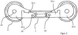
- FIG 2 shows a side view of a chassis 100.
- the swing arms 22 are mounted on the chassis frame 1 via the torsion bars 20.
- the wheel axles 25 are mounted on the swing arms 22 via the wheel bearing 24 (cf. Figure 1 ).
- the swing arms 22 are designed in two parts. Each swing arm 22 comprises a first part 22a and a second part 22b.
- the first part 22a comprises the frame-side swing arm bearing and the second part 22b comprises the wheel-side swing arm bearing.
- Figure 3 shows a top view of the chassis 100.
- the Figure 3 also shows a section through the bearing of a torsion bar 20 and through part of a swing arm 22.
- the four torsion bars 20 and the two connecting elements 21 can be seen, as well as a bearing element 12 designed as a slewing ring segment.
- An alternative bearing element 12' is shown in dashed lines in the form of a single roller mounted in the chassis. Several rollers 12' can also be provided on each chassis side. Of course, the analogous bearing element is also designed on the opposite chassis side, but it is not shown here.
- torsion bars 20 are connected to each other via a connecting element 21 in such a way that the torques in the connecting element 21 are in opposite directions.
- the chassis frame 1 is mainly subjected to vertical, transverse and longitudinal forces. Moments that occur when the torsion bars 20 are compressed are not introduced into the chassis frame 1 or are introduced only to a small extent.
- the torsion bars 20 and the connecting element 21 are part of the primary suspension.
- the mounting of a torsion bar 20 can be seen in a section.
- the torsion bar 20 is mounted in the chassis frame 1 via an elastic bearing 23.
- the elastic bearing 23 allows an axial and radial displacement of the torsion bars 20 of +/- 5mm and also allows a limited rotation of the torsion bars 20.
- the other torsion bars 20 are also mounted via such an elastic bearing 23 (not shown here).
- a swing arm 22 is shown in a partial section, in which a transmission 30 is arranged.
- the output gear of the transmission 30 is mounted on the wheel axle 25.
- Each wheel bearing 24 is also a transmission bearing (not shown here).
- the wheel axle 25 is therefore also the transmission output shaft and is mounted via the wheel bearing 24.
- Two brakes 42 are arranged on each wheel axle 25 and are attached to the swing arm 22 and act on the wheel axles 25.
- the support element 12 is arranged on the chassis frame 1 between the running surfaces 7 of the wheels 4 arranged one behind the other in the direction of travel and can be connected directly to the car body 61 of a rail vehicle carriage 62; 63 (cf. Fig. 9a and 9b ).
- a support element 12 comprises a partially circular guide segment bent towards the outer area.
- the motors 10 are also shown, which are connected to the chassis frame 1.
- the motors 10 are arranged on the inside of the chassis 100 and are attached to the outer surfaces 2 of the chassis frame 1, which face in and against the direction of travel.
- the geometric motor axes are essentially parallel to the outer surfaces 2.
- the motors 10 with motor housing have a cross-sectional diameter of less than 200mm and an output of 50kW, 10-12kU/min at 80km/h.
- the gear ratio is approximately 14:1.
- the motors 10 drive the wheels 4 of the chassis 100 via a gear 30 each.
- the connecting element 21 comprises a bridge 30 and an adjusting device.
- a partial section of the chassis frame 1 and two torsion bars 20 can be seen, which are connected via the bridge 30.
- the adjusting device is arranged on the torsion bars 20.
- the adjusting device comprises adjusting means, here eccentrics 32 and two levers 31. Eccentrics 32 and one torsion bar connected in a rotationally fixed manner to each other are arranged on the bridge 30. Levers 31 are arranged.
- the torsion bars 20 are rotatably mounted in the bridge 30.
- the adjustment device ultimately serves to change the height of the car body above the top edge of the rail (SOK): If the eccentric 32 is turned, the levers 31 are moved and the angular positions of the torsion bars 20 are changed in relation to one another and in relation to the chassis frame 1. This changes the position of the rockers 22 (cf. Figure 1 ) and thus the height of the car body support above the SOK.
- the levers 31 are designed in such a way that they can absorb the moments that arise during transmission. In particular, the levers 31 are therefore more solidly constructed than shown.
- Figure 5 shows a schematic side view of an alternative adjustment device.
- the adjustment device here comprises a swing arm 22, adjusting elements 34 and locking elements 35.
- the swing arm 22 is divided into a frame part 22a on the chassis frame side and a wheel part 22b on the wheel side.
- the adjusting elements 34 and the locking elements 35 are arranged on the swing arm 22.
- the positions of the frame part 22a and the wheel part 22b are adjustable relative to one another and can be fixed in different positions by the adjusting elements 34 and locking elements 35.
- the adjusting elements 34 here comprise elongated holes and screws.
- the locking elements 35 are in the form of a locking lug and a counter-locking piece attached to the wheel part 22b.
- the counter-locking piece has a fixed locking position.
- the adjustment can be carried out by either loosening the adjusting elements 34 and moving the frame part 22a and the wheel part 22b towards one another and/or by inserting a counter-locking piece with a different locking position or by changing the position of the counter-locking piece.
- Figure 6 shows a schematic side view of a magnetic rail brake 40.
- the solid lines show the position of wheel 4, swing arm 22 and chassis frame 1 in a first loading state.
- the indicated dashed lines show the Position of the components in a second loading state in which the chassis frame 1 is compressed by the vertical frame displacement z.
- the magnetic rail brake 40 comprises a brake shoe 43, a cable 41 and a deflection roller Ro.
- the cable 41 is attached at one end to the brake attachment point B on the brake shoe 43 and at the other end to the frame attachment point C on the chassis frame 1.
- the geometric wheel axis H is arranged at a horizontal swing arm length a from the geometric swing arm axis A.
- the deflection roller Ro is arranged a horizontal swing arm length c away from the geometric swing arm axis A.
- the cable 41 leads vertically in a first cable section from the brake attachment point B to a deflection roller Ro attached to the swing arm 22. In a second cable section, the cable 41 leads from the deflection roller Ro at an angle ⁇ away from the first cable section to the frame attachment point C on the chassis frame 1.
- the second cable section has the initial length s o in the non-compressed position and the length s1 in the compressed position.
- the position of the geometric swing arm axis A shifts from the initial position Ao to the compressed position A1: Under the vertical deflection of the chassis frame 1, the vertical frame displacement z, the swing arm 22 rotates around the geometric swing arm axis A in the starting position Ao into the rotation position A1.
- the deflection roller Ro moves to the position R1, resulting in the vertical roller displacement z R.
- FIGS 7a and 7b show schematic views of a roll stiffening of the chassis 100:
- Figure 7a shows a sectional view through the chassis frame 1 in the direction of travel
- Figure 7b shows a section through a rail vehicle carriage 62; 63 transverse to the direction of travel (cf. Figures 9a and 9b ).
- the solid lines show the position of the wheels 4, rockers 22, torsion bars 20, the chassis frame 1 and the car body 61 in a first state.
- the dashed lines show the position of these elements in an inclined position of the car body 61.
- Figure 7a shows two torsion bars 20, a connecting element 21 and two spring elements 50.
- the torsion bars 20 are connected via a connecting element 21 and via elastic bearings 23 to the chassis frame 1 (cf. Figure 3 ).
- the spring elements 50 are arranged between the chassis frame 1 and the connecting element 21. In a driving position of the rail vehicle, one spring element 50 is arranged above and one below the connecting element 21 and is connected to the chassis frame 1.
- Figure 7b shows a car body 61, two wheels 4, the secondary suspension 3, two torsion bars 20 and four spring elements 50.
- the car body 61 is connected to the chassis frame 1 via the secondary suspension 3.
- the wheels 4 are mounted on the chassis frame 1 via rockers 22 and torsion bars 20.
- the tilting forces are transferred to the chassis frame 1 via the secondary suspension 3, so that the chassis frame 1 is also tilted.
- the inclination movement is transmitted from the chassis frame 1 to the spring elements 50, whereby they at least partially absorb the inclination movement.
- the chassis frame 1 is therefore partially supported on the connecting elements 21 via the spring elements 50.
- torsion bars 20 always remain parallel to the wheel axles 25 or parallel to the rail plane, even when the primary suspension is compressed and extended (cf. Figure 3 ).
- Left- and right-hand torsion bars 20 therefore remain parallel to each other and move up and down within the chassis frame 1 under the influence of rolling (shown in dashed lines in the figure).
- This design-related property is used to stiffen the primary suspension during rolling.
- the Up and down movement is restricted or made more difficult by means of springs 50 between the torsion bar ends and the chassis frame 1.
- the spring elements 50 are arranged between the center of the connecting element 21 and the inner contour of the chassis frame 1.
- the spring elements 50 are made of rubber.
- Figure 8 shows a chassis side of a chassis 100 in a top view and a section through a swing arm 22.
- a chassis 100 a mirror-image arrangement of the elements shown is provided.
- a wheel 4 in a standard gauge position is shown in solid lines.
- the wheel axles are interchangeable.
- a wheel axle with a wheel 4' is shown here in dashed lines in a narrow gauge position.
- a chassis 100 is provided with a motor 10 and a gearbox 30 per wheel 4.
- the two motors 10 of a wheel axle, whose motor axes are aligned, are connected via a clutch 11.
- the clutch 11 opens depending on the speed and torque load: At low speeds, the clutch 11 is open. At high speeds, the clutch 11 is closed. If there are large torque differences between the coupled parts, the clutch 11 can slip.
- the torsion bars 20 are mounted in the chassis frame 1 via the elastic bearings 23 and are connected at their end located in the interior of the chassis 100 by the connecting element 21.
- the connecting element 21 accommodates the torsion bars 20 in a rotationally fixed manner. At their other end, the torsion bars are connected in a rotationally fixed manner to the rockers 22.
- the rockers 22 each accommodate the gear 30 for driven wheels 4.
- the gear 30 is connected to the engine 10 via the compensating coupling 31.
- the coupling 31 serves the Compensation of the offset between the engine axle and the transmission input axle that occurs when the swing arms 22 are compressed.
- the wheels 4 are arranged on the wheel axle 25, which is also the transmission output shaft.
- the swing arm 22 also carries a brake 42.
- one brake 42 is usually arranged on each swing arm 22 for each wheel 4 (cf. Figure 3 ).
- the brake 42 is arranged on the swing arm 22 and acts directly on the wheel axle 25.
- the wheel axle 25 is mounted directly in the swing arm 22 by means of wheel bearings 24 and is not further supported relative to the chassis frame 1.
- the figure also shows the secondary suspension 3 schematically.
- the secondary suspension 3 is arranged in the middle of the chassis 100 as seen in the direction of travel.
- Two secondary spring elements 3 are arranged on each chassis side.
- FIGS. 9a and 9b each show a rail vehicle schematically with bogies 100.
- Figure 9a shows a rail vehicle 60 consisting of three rail vehicle carriages 62, each with two bogies 100 and one car body 61. These bogies 100 are designed here as bogies.
- Figure 9b shows a rail vehicle 60, which comprises three rail vehicle carriages 63, each with a chassis 100 and a car body 61.
- the chassis 100 are not designed to rotate.
- the car bodies 64 are arranged between two rail vehicle carriages 63 and are carried by the rail vehicle carriages 63.
- Figures 10a and 10b show part of a side view of a chassis with damping system and a schematic view of a damping system. The situation before compression is shown in solid lines. The compressed position is shown in dashed lines.
- Figure 10a shows a part of a sectional view through a chassis 100 in the direction of travel.
- the damping system comprises a damping element 13, a portal axle 9, a chassis frame 1 and a motion transmission element 14.
- the portal axle 9 has a side part 15 at one end, which is mounted on the swing arm 22 so as to be rotatable about the geometric wheel axis V.
- the portal axle 9 also comprises a bridge support 16 which is connected to the side part 15.
- the damping element 13 is arranged between the chassis frame 1 and the bridge support 16 and has a substantially horizontal damping direction in the direction of travel.
- the stroke of the damping element 13 can be changed by the position of the bridge support 16.
- One end of the motion transmission element 14 is rotatably connected to the chassis frame 1.
- the other end of the motion transmission element 14 is rotatably connected to the side part 15 at the motion transmission point P.
- the motion transmission point P is arranged at a handlebar distance L from the geometric wheel axis V.
- the damping connection point Q is arranged at a vertical distance m from the geometric wheel axis V.
- the chassis frame 1 When the primary suspension is compressed, the chassis frame 1 is displaced by the vertical frame displacement z.
- the connection point of the motion transmission element 14 with the chassis frame 1 is displaced by this movement.
- the motion transmission element 14 in turn transfers this movement to the side part 15, so that the motion transmission point P and thus the side part 15 and the bridge girder 16 are pivoted about the geometric wheel axis V at an angle ⁇ .
- tan ⁇ ⁇ z/L applies.
- the deflection of the bridge girder 16 at the damper connection point Q is approximately u ⁇ m/L * z for small z and thus small ⁇ .
- the deflection of the portal axis 9 is therefore larger than the deflection if the geometry is chosen appropriately.
- Figure 10b shows a schematic representation of the pivoting of the portal axis 9 (cf. Figure 10a ).
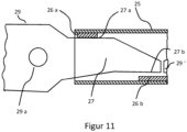
- Figure 11 shows a schematic section through a part of a connection of a swing arm 22 with a stiffening element 25 in a first loading state.
- the stiffening element 25 is designed here as a hollow beam.
- the swing arm 22 comprises an extension element 29 which is attached to the housing of the swing arm 22.
- the extension element 29 comprises a fastening body with a bearing point 29a and a wedge body 27 with an upper contact point 27a.
- the fastening body and wedge body 27 are integrally formed.
- the wedge body 27 has a plan which essentially comprises a bent wedge shape.
- the stiffening element 25 has a support element 26a and a support element 26b inside. In the fastening state, the support element 26a is arranged on the upper side of the stiffening element 25 and the support element 26b is arranged on the lower side.
- the support element 26a and the support element 26b each comprise a contact element made of polyurethane.
- the support element 26a has a thickness of essentially 2mm, unlike what is shown in the figure.
- the support element 26b has a thickness of essentially 7-9mm, unlike what is shown in the figure.
- the stiffening element 25 rests with the support elements 26a on the extension element 29. There is a distance between the extension element 29 and the support element 26b.
- the extension element 29 rotates around the geometric axis of the bearing 29a.
- the end of the wedge body 27 with the lower contact point 27b of the extension element 29 moves downwards until it hits the support element 26b.
- the support element 26b is designed here as a polyurethane contact element for both rockers 22 on one chassis side. If the extension element 29 and thus the rocker 22 rests on the support element 26b, the extension element 29 wedges itself into the stiffening element 25. This stiffens the primary suspension.
- the Figures 12 each show a section through a stiffening element 25 shown in Figure 11 in the longitudinal direction.
- the rockers 22 of one chassis side can be seen, which are connected via the stiffening element 25 in a first and a second load state.
- Figure 12a shows the stress level that has already Figure 11 was described.
- Figure 12b shows a second load condition.
- the load in the second load condition is greater than the first load condition.
- the rockers 22 are adjusted according to the load from the original position of Figure 12a rotated around the geometric axis of the bearing point 29a.
- the load shown corresponds to the load that prevails after a torsion bar of a primary suspension breaks.
- the extension elements 29 are connected to the stiffening element 25 via the support elements 26a and the support element 26b.
- the stiffening element 25 has been elastically and plastically deformed in accordance with the rotation of the rockers 22.
Landscapes
- Engineering & Computer Science (AREA)
- Mechanical Engineering (AREA)
- Transportation (AREA)
- Chemical & Material Sciences (AREA)
- Combustion & Propulsion (AREA)
- Vehicle Body Suspensions (AREA)
Priority Applications (1)
| Application Number | Priority Date | Filing Date | Title |
|---|---|---|---|
| EP24216752.6A EP4491487B1 (fr) | 2019-03-22 | 2019-03-22 | Train de roulement pour un véhicule ferroviaire et véhicule ferroviaire comprenant au moins un train de roulement, véhicule ferroviaire comprenant au moins un wagon de chemin de fer et procédé de réglage en hauteur d'une caisse d'un véhicule ferroviaire |
Applications Claiming Priority (3)
| Application Number | Priority Date | Filing Date | Title |
|---|---|---|---|
| PCT/EP2019/057206 WO2020192860A1 (fr) | 2019-03-22 | 2019-03-22 | Dispositif de roulement pour un véhicule ferroviaire ainsi que wagon ferroviaire muni d'au moins un dispositif de roulement, véhicule ferroviaire muni d'au moins un wagon ferroviaire et procédé de réglage en hauteur d'une caisse de wagon d'un wagon ferroviaire |
| EP19714571.7A EP3941795B1 (fr) | 2019-03-22 | 2019-03-22 | Dispositif de roulement pour un véhicule ferroviaire ainsi que wagon ferroviaire muni d'au moins un dispositif de roulement, véhicule ferroviaire muni d'au moins un wagon ferroviaire et procédé de réglage en hauteur d'une caisse de wagon d'un wagon ferroviaire |
| EP24216752.6A EP4491487B1 (fr) | 2019-03-22 | 2019-03-22 | Train de roulement pour un véhicule ferroviaire et véhicule ferroviaire comprenant au moins un train de roulement, véhicule ferroviaire comprenant au moins un wagon de chemin de fer et procédé de réglage en hauteur d'une caisse d'un véhicule ferroviaire |
Related Parent Applications (1)
| Application Number | Title | Priority Date | Filing Date |
|---|---|---|---|
| EP19714571.7A Division EP3941795B1 (fr) | 2019-03-22 | 2019-03-22 | Dispositif de roulement pour un véhicule ferroviaire ainsi que wagon ferroviaire muni d'au moins un dispositif de roulement, véhicule ferroviaire muni d'au moins un wagon ferroviaire et procédé de réglage en hauteur d'une caisse de wagon d'un wagon ferroviaire |
Publications (4)
| Publication Number | Publication Date |
|---|---|
| EP4491487A2 true EP4491487A2 (fr) | 2025-01-15 |
| EP4491487A3 EP4491487A3 (fr) | 2025-05-14 |
| EP4491487B1 EP4491487B1 (fr) | 2026-07-01 |
| EP4491487C0 EP4491487C0 (fr) | 2026-07-01 |
Family
ID=65995681
Family Applications (2)
| Application Number | Title | Priority Date | Filing Date |
|---|---|---|---|
| EP19714571.7A Active EP3941795B1 (fr) | 2019-03-22 | 2019-03-22 | Dispositif de roulement pour un véhicule ferroviaire ainsi que wagon ferroviaire muni d'au moins un dispositif de roulement, véhicule ferroviaire muni d'au moins un wagon ferroviaire et procédé de réglage en hauteur d'une caisse de wagon d'un wagon ferroviaire |
| EP24216752.6A Active EP4491487B1 (fr) | 2019-03-22 | 2019-03-22 | Train de roulement pour un véhicule ferroviaire et véhicule ferroviaire comprenant au moins un train de roulement, véhicule ferroviaire comprenant au moins un wagon de chemin de fer et procédé de réglage en hauteur d'une caisse d'un véhicule ferroviaire |
Family Applications Before (1)
| Application Number | Title | Priority Date | Filing Date |
|---|---|---|---|
| EP19714571.7A Active EP3941795B1 (fr) | 2019-03-22 | 2019-03-22 | Dispositif de roulement pour un véhicule ferroviaire ainsi que wagon ferroviaire muni d'au moins un dispositif de roulement, véhicule ferroviaire muni d'au moins un wagon ferroviaire et procédé de réglage en hauteur d'une caisse de wagon d'un wagon ferroviaire |
Country Status (4)
| Country | Link |
|---|---|
| US (1) | US12365368B2 (fr) |
| EP (2) | EP3941795B1 (fr) |
| CA (1) | CA3133134A1 (fr) |
| WO (1) | WO2020192860A1 (fr) |
Families Citing this family (4)
| Publication number | Priority date | Publication date | Assignee | Title |
|---|---|---|---|---|
| EP4013655B1 (fr) * | 2019-09-30 | 2024-04-24 | Siemens Mobility Austria GmbH | Train de roulement pour véhicule ferroviaire |
| DE102022104793B3 (de) | 2022-03-01 | 2023-02-16 | Deutsches Zentrum für Luft- und Raumfahrt e.V. | Schienenfahrzeug |
| AT526054B1 (de) | 2022-10-24 | 2023-11-15 | Siemens Mobility Austria Gmbh | Fahrwerk für ein Schienenfahrzeug und Schienenfahrzeug |
| EP4763655A1 (fr) * | 2024-12-19 | 2026-06-24 | Stadler Rail AG | Train de roulement pour véhicule ferroviaire, véhicule ferroviaire et procédé d'ouverture ou de fermeture d'un embrayage |
Citations (4)
| Publication number | Priority date | Publication date | Assignee | Title |
|---|---|---|---|---|
| US2473714A (en) | 1945-07-03 | 1949-06-21 | Goodrich Co B F | Rail truck suspension |
| CH264180A (de) | 1946-12-19 | 1949-09-30 | Sig Schweiz Industrieges | Drehgestell für Schienenfahrzeuge. |
| DE2616923A1 (de) | 1975-04-18 | 1976-10-21 | Politechnika Poznanska | Torsionsstabfederungssystem |
| EP0548044A1 (fr) | 1991-12-19 | 1993-06-23 | Bombardier-Wien Schienenfahrzeuge Aktiengesellschaft | Véhicule ferroviaire |
Family Cites Families (9)
| Publication number | Priority date | Publication date | Assignee | Title |
|---|---|---|---|---|
| CH317007A (de) * | 1953-08-28 | 1956-10-31 | Inventio Ag | Zweiachsiges Drehgestell für Schienenfahrzeuge |
| DE2913539A1 (de) * | 1979-04-04 | 1980-10-16 | Thyssen Industrie | Antriebsdrehgestell fuer schienenfahrzeuge wie strassenbahnen o.dgl. |
| DE3931912A1 (de) * | 1989-09-25 | 1991-04-04 | Eickhoff Geb | Einzelradlagerung eines triebrades an schienenfahrzeugen |
| FR2664222B1 (fr) * | 1990-07-05 | 1993-01-15 | Alsthom Gec | Bogie a roues independantes motorisees pour vehicule ferroviaire. |
| IT1257195B (it) * | 1992-05-26 | 1996-01-10 | Carrello per veicoli ferrotranviari con motori di trazione e riduttorisospesi al telaio. | |
| GB9410479D0 (en) * | 1994-05-25 | 1994-07-13 | Abb Transportation Ltd | Rail vehicle bogies |
| DE4446043C1 (de) * | 1994-12-22 | 1996-03-07 | Siemens Ag | Fahrwerk für Schienenfahrzeuge |
| FR2946307B1 (fr) * | 2009-06-05 | 2011-08-05 | Alstom Transport Sa | Bogie moteur de vehicule ferroviaire comprenant un moteur semi-suspendu |
| FR3049252B1 (fr) * | 2016-03-25 | 2018-04-20 | Alstom Transport Technologies | Bogie comprenant une liaison rigide entre les boites d'essieu, et vehicule ferroviaire associe |
-
2019
- 2019-03-22 CA CA3133134A patent/CA3133134A1/fr active Pending
- 2019-03-22 WO PCT/EP2019/057206 patent/WO2020192860A1/fr not_active Ceased
- 2019-03-22 US US17/441,471 patent/US12365368B2/en active Active
- 2019-03-22 EP EP19714571.7A patent/EP3941795B1/fr active Active
- 2019-03-22 EP EP24216752.6A patent/EP4491487B1/fr active Active
Patent Citations (4)
| Publication number | Priority date | Publication date | Assignee | Title |
|---|---|---|---|---|
| US2473714A (en) | 1945-07-03 | 1949-06-21 | Goodrich Co B F | Rail truck suspension |
| CH264180A (de) | 1946-12-19 | 1949-09-30 | Sig Schweiz Industrieges | Drehgestell für Schienenfahrzeuge. |
| DE2616923A1 (de) | 1975-04-18 | 1976-10-21 | Politechnika Poznanska | Torsionsstabfederungssystem |
| EP0548044A1 (fr) | 1991-12-19 | 1993-06-23 | Bombardier-Wien Schienenfahrzeuge Aktiengesellschaft | Véhicule ferroviaire |
Also Published As
| Publication number | Publication date |
|---|---|
| EP4491487B1 (fr) | 2026-07-01 |
| EP3941795A1 (fr) | 2022-01-26 |
| EP4491487A3 (fr) | 2025-05-14 |
| EP3941795B1 (fr) | 2024-12-04 |
| EP4491487C0 (fr) | 2026-07-01 |
| EP3941795C0 (fr) | 2024-12-04 |
| US20220169291A1 (en) | 2022-06-02 |
| WO2020192860A1 (fr) | 2020-10-01 |
| US12365368B2 (en) | 2025-07-22 |
| CA3133134A1 (fr) | 2020-10-01 |
Similar Documents
| Publication | Publication Date | Title |
|---|---|---|
| EP2414207B1 (fr) | Véhicule à compensation du roulis | |
| EP3941795B1 (fr) | Dispositif de roulement pour un véhicule ferroviaire ainsi que wagon ferroviaire muni d'au moins un dispositif de roulement, véhicule ferroviaire muni d'au moins un wagon ferroviaire et procédé de réglage en hauteur d'une caisse de wagon d'un wagon ferroviaire | |
| EP2477864A1 (fr) | Véhicule ferroviaire présentant une liaison souple dans le sens transversal de la carrosserie au châssis | |
| EP0944513B1 (fr) | Chassis de bogie pour materiel ferroviaire roulant | |
| DE2617896A1 (de) | Drehgestell fuer eisenbahnwagen | |
| DE2940892A1 (de) | Verfahren zum umruesten eines eisenbahn-fahrgestells mit einem mechanismus zur radsatzsteuerung | |
| EP0547188B1 (fr) | Bogie pour vehicules de chemins de fer a grande vitesse | |
| EP1915283B1 (fr) | Vehicule equipe de dispositifs antiroulis | |
| EP3544875B1 (fr) | Châssis pour véhicules sur rails | |
| EP0549731B1 (fr) | Dispositif de roulement a roues independantes pour vehicules sur rails | |
| EP0649782B1 (fr) | Véhicule ferroviaire et train de roulement pour un tel véhicule | |
| AT409843B (de) | Fahrwerk für ein schienenfahrzeug | |
| EP2121408B1 (fr) | Châssis de véhicule ferroviaire | |
| DE1605126B2 (de) | Triebgestell für Schienenfahrzeuge | |
| EP2089263B1 (fr) | Train de roulement pour un véhicule ferroviaire | |
| DE19548437C1 (de) | Zweiachsiges Schienenfahrzeug-Drehgestell | |
| WO2002026542A1 (fr) | Vehicule sur rails a ajustement radial des axes de roue | |
| EP0439573B1 (fr) | Chassis pour vehicules surbaisses | |
| EP2939898B1 (fr) | Boggie pour véhicules sur rails ayant trois essieux montés | |
| EP0930210B1 (fr) | Train de roulement pour véhicules ferroviaires et véhicule ferroviaire avec au moins un tel train de roulement | |
| EP3409516B1 (fr) | Châssis actif | |
| DE1755733A1 (de) | Drehgestell fuer schienenfahrzeuge | |
| EP0763454B1 (fr) | Train de roulement pour un véhicule ferroviaire, notamment pour un véhicule ferroviaire à plancher bas | |
| EP0641702A1 (fr) | Stabilisateur de rotation hydraulique pour véhicules ferroviaires | |
| DE3317080A1 (de) | Drehgestell fuer schienenfahrzeuge |
Legal Events
| Date | Code | Title | Description |
|---|---|---|---|
| PUAI | Public reference made under article 153(3) epc to a published international application that has entered the european phase |
Free format text: ORIGINAL CODE: 0009012 |
|
| STAA | Information on the status of an ep patent application or granted ep patent |
Free format text: STATUS: THE APPLICATION HAS BEEN PUBLISHED |
|
| AC | Divisional application: reference to earlier application |
Ref document number: 3941795 Country of ref document: EP Kind code of ref document: P |
|
| AK | Designated contracting states |
Kind code of ref document: A2 Designated state(s): AL AT BE BG CH CY CZ DE DK EE ES FI FR GB GR HR HU IE IS IT LI LT LU LV MC MK MT NL NO PL PT RO RS SE SI SK SM TR |
|
| REG | Reference to a national code |
Ref country code: DE Ref legal event code: R079 Free format text: PREVIOUS MAIN CLASS: B61F0015000000 Ipc: B61D0013000000 Ref country code: DE Ref legal event code: R079 Ref document number: 502019014794 Country of ref document: DE Free format text: PREVIOUS MAIN CLASS: B61F0015000000 Ipc: B61D0013000000 |
|
| PUAL | Search report despatched |
Free format text: ORIGINAL CODE: 0009013 |
|
| AK | Designated contracting states |
Kind code of ref document: A3 Designated state(s): AL AT BE BG CH CY CZ DE DK EE ES FI FR GB GR HR HU IE IS IT LI LT LU LV MC MK MT NL NO PL PT RO RS SE SI SK SM TR |
|
| RIC1 | Information provided on ipc code assigned before grant |
Ipc: B61F 5/52 20060101ALI20250407BHEP Ipc: B61F 3/16 20060101ALI20250407BHEP Ipc: B61F 15/00 20060101ALI20250407BHEP Ipc: B61C 9/50 20060101ALI20250407BHEP Ipc: B61F 5/30 20060101ALI20250407BHEP Ipc: B61F 5/22 20060101ALI20250407BHEP Ipc: B61F 5/50 20060101ALI20250407BHEP Ipc: B61F 3/04 20060101ALI20250407BHEP Ipc: B61D 13/00 20060101AFI20250407BHEP |
|
| STAA | Information on the status of an ep patent application or granted ep patent |
Free format text: STATUS: REQUEST FOR EXAMINATION WAS MADE |
|
| 17P | Request for examination filed |
Effective date: 20250917 |
|
| GRAP | Despatch of communication of intention to grant a patent |
Free format text: ORIGINAL CODE: EPIDOSNIGR1 |
|
| STAA | Information on the status of an ep patent application or granted ep patent |
Free format text: STATUS: GRANT OF PATENT IS INTENDED |
|
| INTG | Intention to grant announced |
Effective date: 20260220 |
|
| GRAS | Grant fee paid |
Free format text: ORIGINAL CODE: EPIDOSNIGR3 |
|
| GRAA | (expected) grant |
Free format text: ORIGINAL CODE: 0009210 |
|
| STAA | Information on the status of an ep patent application or granted ep patent |
Free format text: STATUS: THE PATENT HAS BEEN GRANTED |
|
| AC | Divisional application: reference to earlier application |
Ref document number: 3941795 Country of ref document: EP Kind code of ref document: P |
|
| AK | Designated contracting states |
Kind code of ref document: B1 Designated state(s): AL AT BE BG CH CY CZ DE DK EE ES FI FR GB GR HR HU IE IS IT LI LT LU LV MC MK MT NL NO PL PT RO RS SE SI SK SM TR |
|
| REG | Reference to a national code |
Ref country code: CH Ref legal event code: F10 Free format text: ST27 STATUS EVENT CODE: U-0-0-F10-F00 (AS PROVIDED BY THE NATIONAL OFFICE) Effective date: 20260701 Ref country code: GB Ref legal event code: FG4D Free format text: NOT ENGLISH |
|
| REG | Reference to a national code |
Ref country code: CH Ref legal event code: R17 Free format text: ST27 STATUS EVENT CODE: U-0-0-R10-R17 (AS PROVIDED BY THE NATIONAL OFFICE) Effective date: 20260715 |
|
| REG | Reference to a national code |
Ref country code: DE Ref legal event code: R096 Ref document number: 502019014794 Country of ref document: DE |
|
| REG | Reference to a national code |
Ref country code: IE Ref legal event code: FG4D Free format text: LANGUAGE OF EP DOCUMENT: GERMAN |