EP4491768A1 - Separator und elektrochemische umwandlungszelle damit - Google Patents
Separator und elektrochemische umwandlungszelle damit Download PDFInfo
- Publication number
- EP4491768A1 EP4491768A1 EP23792161.4A EP23792161A EP4491768A1 EP 4491768 A1 EP4491768 A1 EP 4491768A1 EP 23792161 A EP23792161 A EP 23792161A EP 4491768 A1 EP4491768 A1 EP 4491768A1
- Authority
- EP
- European Patent Office
- Prior art keywords
- separator
- porous structure
- structure layer
- hydrophilic
- exchange membrane
- Prior art date
- Legal status (The legal status is an assumption and is not a legal conclusion. Google has not performed a legal analysis and makes no representation as to the accuracy of the status listed.)
- Pending
Links
Images

Classifications
-
- B—PERFORMING OPERATIONS; TRANSPORTING
- B01—PHYSICAL OR CHEMICAL PROCESSES OR APPARATUS IN GENERAL
- B01D—SEPARATION
- B01D69/00—Semi-permeable membranes for separation processes or apparatus characterised by their form, structure or properties; Manufacturing processes specially adapted therefor
- B01D69/12—Composite membranes; Ultra-thin membranes
- B01D69/1213—Laminated layers
-
- B—PERFORMING OPERATIONS; TRANSPORTING
- B01—PHYSICAL OR CHEMICAL PROCESSES OR APPARATUS IN GENERAL
- B01D—SEPARATION
- B01D69/00—Semi-permeable membranes for separation processes or apparatus characterised by their form, structure or properties; Manufacturing processes specially adapted therefor
- B01D69/12—Composite membranes; Ultra-thin membranes
- B01D69/1216—Three or more layers
-
- C—CHEMISTRY; METALLURGY
- C25—ELECTROLYTIC OR ELECTROPHORETIC PROCESSES; APPARATUS THEREFOR
- C25B—ELECTROLYTIC OR ELECTROPHORETIC PROCESSES FOR THE PRODUCTION OF COMPOUNDS OR NON-METALS; APPARATUS THEREFOR
- C25B1/00—Electrolytic production of inorganic compounds or non-metals
- C25B1/01—Products
- C25B1/23—Carbon monoxide or syngas
-
- C—CHEMISTRY; METALLURGY
- C25—ELECTROLYTIC OR ELECTROPHORETIC PROCESSES; APPARATUS THEREFOR
- C25B—ELECTROLYTIC OR ELECTROPHORETIC PROCESSES FOR THE PRODUCTION OF COMPOUNDS OR NON-METALS; APPARATUS THEREFOR
- C25B13/00—Diaphragms; Spacing elements
- C25B13/02—Diaphragms; Spacing elements characterised by shape or form
-
- C—CHEMISTRY; METALLURGY
- C25—ELECTROLYTIC OR ELECTROPHORETIC PROCESSES; APPARATUS THEREFOR
- C25B—ELECTROLYTIC OR ELECTROPHORETIC PROCESSES FOR THE PRODUCTION OF COMPOUNDS OR NON-METALS; APPARATUS THEREFOR
- C25B13/00—Diaphragms; Spacing elements
- C25B13/04—Diaphragms; Spacing elements characterised by the material
- C25B13/08—Diaphragms; Spacing elements characterised by the material based on organic materials
-
- H—ELECTRICITY
- H01—ELECTRIC ELEMENTS
- H01M—PROCESSES OR MEANS, e.g. BATTERIES, FOR THE DIRECT CONVERSION OF CHEMICAL ENERGY INTO ELECTRICAL ENERGY
- H01M8/00—Fuel cells; Manufacture thereof
- H01M8/10—Fuel cells with solid electrolytes
- H01M8/1016—Fuel cells with solid electrolytes characterised by the electrolyte material
- H01M8/1018—Polymeric electrolyte materials
- H01M8/102—Polymeric electrolyte materials characterised by the chemical structure of the main chain of the ion-conducting polymer
- H01M8/1023—Polymeric electrolyte materials characterised by the chemical structure of the main chain of the ion-conducting polymer having only carbon, e.g. polyarylenes, polystyrenes or polybutadiene-styrenes
-
- H—ELECTRICITY
- H01—ELECTRIC ELEMENTS
- H01M—PROCESSES OR MEANS, e.g. BATTERIES, FOR THE DIRECT CONVERSION OF CHEMICAL ENERGY INTO ELECTRICAL ENERGY
- H01M8/00—Fuel cells; Manufacture thereof
- H01M8/10—Fuel cells with solid electrolytes
- H01M8/1016—Fuel cells with solid electrolytes characterised by the electrolyte material
- H01M8/1018—Polymeric electrolyte materials
- H01M8/102—Polymeric electrolyte materials characterised by the chemical structure of the main chain of the ion-conducting polymer
- H01M8/1025—Polymeric electrolyte materials characterised by the chemical structure of the main chain of the ion-conducting polymer having only carbon and oxygen, e.g. polyethers, sulfonated polyetheretherketones [S-PEEK], sulfonated polysaccharides, sulfonated celluloses or sulfonated polyesters
-
- H—ELECTRICITY
- H01—ELECTRIC ELEMENTS
- H01M—PROCESSES OR MEANS, e.g. BATTERIES, FOR THE DIRECT CONVERSION OF CHEMICAL ENERGY INTO ELECTRICAL ENERGY
- H01M8/00—Fuel cells; Manufacture thereof
- H01M8/10—Fuel cells with solid electrolytes
- H01M8/1016—Fuel cells with solid electrolytes characterised by the electrolyte material
- H01M8/1018—Polymeric electrolyte materials
- H01M8/102—Polymeric electrolyte materials characterised by the chemical structure of the main chain of the ion-conducting polymer
- H01M8/103—Polymeric electrolyte materials characterised by the chemical structure of the main chain of the ion-conducting polymer having nitrogen, e.g. sulfonated polybenzimidazoles [S-PBI], polybenzimidazoles with phosphoric acid, sulfonated polyamides [S-PA] or sulfonated polyphosphazenes [S-PPh]
-
- H—ELECTRICITY
- H01—ELECTRIC ELEMENTS
- H01M—PROCESSES OR MEANS, e.g. BATTERIES, FOR THE DIRECT CONVERSION OF CHEMICAL ENERGY INTO ELECTRICAL ENERGY
- H01M8/00—Fuel cells; Manufacture thereof
- H01M8/10—Fuel cells with solid electrolytes
- H01M8/1016—Fuel cells with solid electrolytes characterised by the electrolyte material
- H01M8/1018—Polymeric electrolyte materials
- H01M8/1039—Polymeric electrolyte materials halogenated, e.g. sulfonated polyvinylidene fluorides
-
- H—ELECTRICITY
- H01—ELECTRIC ELEMENTS
- H01M—PROCESSES OR MEANS, e.g. BATTERIES, FOR THE DIRECT CONVERSION OF CHEMICAL ENERGY INTO ELECTRICAL ENERGY
- H01M8/00—Fuel cells; Manufacture thereof
- H01M8/10—Fuel cells with solid electrolytes
- H01M8/1016—Fuel cells with solid electrolytes characterised by the electrolyte material
- H01M8/1018—Polymeric electrolyte materials
- H01M8/1041—Polymer electrolyte composites, mixtures or blends
- H01M8/1053—Polymer electrolyte composites, mixtures or blends consisting of layers of polymers with at least one layer being ionically conductive
-
- H—ELECTRICITY
- H01—ELECTRIC ELEMENTS
- H01M—PROCESSES OR MEANS, e.g. BATTERIES, FOR THE DIRECT CONVERSION OF CHEMICAL ENERGY INTO ELECTRICAL ENERGY
- H01M8/00—Fuel cells; Manufacture thereof
- H01M8/10—Fuel cells with solid electrolytes
- H01M8/1016—Fuel cells with solid electrolytes characterised by the electrolyte material
- H01M8/1018—Polymeric electrolyte materials
- H01M8/1067—Polymeric electrolyte materials characterised by their physical properties, e.g. porosity, ionic conductivity or thickness
-
- H—ELECTRICITY
- H01—ELECTRIC ELEMENTS
- H01M—PROCESSES OR MEANS, e.g. BATTERIES, FOR THE DIRECT CONVERSION OF CHEMICAL ENERGY INTO ELECTRICAL ENERGY
- H01M8/00—Fuel cells; Manufacture thereof
- H01M8/18—Regenerative fuel cells, e.g. redox flow batteries or secondary fuel cells
- H01M8/182—Regeneration by thermal means
-
- B—PERFORMING OPERATIONS; TRANSPORTING
- B01—PHYSICAL OR CHEMICAL PROCESSES OR APPARATUS IN GENERAL
- B01D—SEPARATION
- B01D2325/00—Details relating to properties of membranes
- B01D2325/02—Details relating to pores or porosity of the membranes
- B01D2325/0283—Pore size
- B01D2325/02834—Pore size more than 0.1 and up to 1 µm
-
- B—PERFORMING OPERATIONS; TRANSPORTING
- B01—PHYSICAL OR CHEMICAL PROCESSES OR APPARATUS IN GENERAL
- B01D—SEPARATION
- B01D2325/00—Details relating to properties of membranes
- B01D2325/36—Hydrophilic membranes
-
- B—PERFORMING OPERATIONS; TRANSPORTING
- B01—PHYSICAL OR CHEMICAL PROCESSES OR APPARATUS IN GENERAL
- B01D—SEPARATION
- B01D2325/00—Details relating to properties of membranes
- B01D2325/38—Hydrophobic membranes
-
- B—PERFORMING OPERATIONS; TRANSPORTING
- B01—PHYSICAL OR CHEMICAL PROCESSES OR APPARATUS IN GENERAL
- B01D—SEPARATION
- B01D2325/00—Details relating to properties of membranes
- B01D2325/42—Ion-exchange membranes
Definitions
- the present invention relates to a separator and an electrochemical conversion cell including the same.
- Carbon dioxide is a greenhouse gas that contributes to global warming, and thus needs to be reduced. Carbon dioxide may be reduced by means of trapping, chemical conversion, or electrochemical conversion. In particular, the electrochemical conversion may precisely control components so that other synthesis gases may be produced, and thus may give better economic benefits than merely removing carbon dioxide.
- the process of electrochemically decomposing carbon dioxide is similar to water electrolysis technology, but in general, a KOH aqueous solution with a certain concentration is used as an electrolyte since activity in an electrochemical reaction is greater in a strong base atmosphere.
- a KOH aqueous solution with a certain concentration is used as an electrolyte since activity in an electrochemical reaction is greater in a strong base atmosphere.
- the transferred electrons react with carbon dioxide and water supplied to the cathode to be decomposed into carbon monoxide and hydroxide ions (OH-), and the generated hydroxide ions react with hydrogen ions (H + ) of the anode to produce water, thereby becoming electrically neutral.
- the above process completes the electrochemical decomposition reaction of carbon dioxide.
- the water supplied along with carbon dioxide is electrolyzed by reacting with the transferred electrons to generate both hydrogen gas and hydroxide ions.
- the reaction between water and electrons is in a relation of competitive reaction to the reaction of generating carbon monoxide.
- the above reactions are electrochemical reactions, and thus an amount of carbon monoxide generated and a ratio of hydrogen/carbon dioxide may be easily controlled through voltage regulation.
- An aspect of the present invention provides improved mechanical properties at room temperature by ensuring that a certain amount of moisture is constantly present in a separator.
- the present invention provides a separator formed to have a structure in which a porous structure layer having hydrophilic or hydrophobic properties is stacked on a surface of an ion exchange membrane, which in turn constantly retains a certain amount of moisture, thereby keeping the performance of the ion exchange membrane at the same level and improving mechanical properties at room temperature, and an electrochemical conversion cell including the same.
- the present invention provides a separator and an electrochemical conversion cell including the same.
- a separator of the present invention forms a structure in which a porous structure layer having hydrophilic or hydrophobic properties is stacked on a surface of an ion exchange membrane, and is capable of keeping a certain level of moisture in the ion exchange membrane even at room temperature for a long period of time, and may thus improve mechanical properties of the ion exchange membrane.
- the separator of the present invention moisture wettability is maintained even at room temperature to prevent the separator from drying out and being damaged or broken, and accordingly, low processability that may be caused by the breakage when cells or stacks are assembled at room temperature may be improved.
- an electrochemical conversion cell including the separator of the present invention includes a separator capable of maintaining moisture wettability even at room temperature, and may thus improve mechanical properties and also have equal or higher levels in terms of carbon monoxide Faraday efficiency, carbon dioxide conversion rate, and voltage of the electrochemical conversion cell.
- a separator of the present invention may include a base membrane, and a hydrophilic porous structure layer or a hydrophobic porous structure layer, which is stacked on at least one side of the base membrane, wherein the base membrane may be an anion exchange membrane, a cation exchange membrane, or an amphoteric ion exchange membrane.
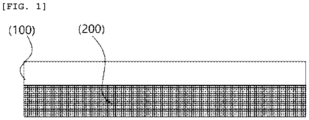
- the separator may include a base membrane and a porous structure layer, and the porous structure layer may be stacked on at least one side of the base membrane.
- the base membrane may be an ion-selective exchange membrane, and the base membrane may include an anion exchange membrane, a cation exchange membrane, or an amphoteric ion exchange membrane.
- the separator of the present invention may be an anion exchange membrane.
- porous structure layer may have hydrophilic or hydrophobic properties.
- the porous structure layer may be stacked on at least one side of the base membrane, and may thus serve to maintain a certain amount of moisture in the base membrane.
- the porous structure layer has a porous structure, and the porous structure indicates a structure having a number of holes, that is, pores, on the surface or inside of a material.
- the pores may have an irregular shape such as a spherical shape, an ellipsoidal shape, or a rod shape, and the pores may have an average diameter of 0.2 um to 0.45 um as will be described later.
- the average diameter of the pores the length of a major axis of surface pores found in a randomly sampled range (10 um or greater in width and 15 um or greater in length) in an image measured using a scanning electron microscope (FE-SEM) may be measured as a pore size.
- the porous structure layer of the present invention has a porous structure, and may thus be light in weight and have excellent mechanical strength, and have low resistance to promote transport of materials through the pores.
- an anion exchange membrane is typically used as a separator of an electrochemical conversion device.
- electrochemical conversion rate according to the electrochemical conversion device is shown to be excellent, but the anion exchange membrane may be easily dried when exposed at room temperature, and the anion exchange membrane is easily dried when assembled to a cell or stack of the electrochemical conversion device at room temperature, and fails to maintain moisture content and may thus be broken or damaged.
- the anion exchange membrane may be stored along with water or a fluid retaining sufficient moisture, but given that a process of assembling a cell or stack is performed at room temperature, moisture in the anion exchange membrane is easily evaporated and the anion exchange membrane may be damaged when the anion exchange membrane is exposed at room temperature although the anion exchange membrane is stored in water having sufficient moisture. Accordingly, the typical anion exchange membrane may critically affect work processability due to such low mechanical properties at room temperature. Therefore, in order to improve or maintain the mechanical properties and work processability of the anion exchange membrane, a certain amount of moisture needs to be constantly present in the anion exchange membrane to maintain moisture wettability.
- the separator of the present invention has the effect of improving the low mechanical properties and low work processability, which are limitations of the typical separator, while maintaining performance equal to or greater than that of the typical separator.
- the separator of the present invention has a porous structure layer having hydrophilic or hydrophobic properties stacked on at least one surface of the base membrane, and may thus maintain a certain amount of moisture in the separator even at room temperature for a long period of time, and accordingly may improve low mechanical properties and low work processability.
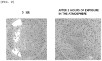
- FIG. 2 shows a state when a typical anion exchange membrane treated with a hydrophilic coating is exposed at room temperature for 2 hours
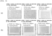
- FIG. 3 shows a state when a separator in which a hydrophilic porous structure layer is stacked on a surface of the anion exchange membrane of the present invention is exposed at the same room temperature for 2 hours.
- (a) from FIG. 3 is one to which surface hydrophilic- or hydrophobic-treated PTFE is applied
- FIG 3 is one to which surface hydrophilic- or hydrophobic-treated PVDF is applied.
- the separator may not be deformed compared to an initial shape when the separator is exposed at room temperature for 2 hours or more.
- the typical separator when the separator of the present invention and the typical separator are equally exposed at room temperature, the typical separator is broken or mechanically warped due to moisture evaporation after 1 hour to 2 hours.
- the separator of the present invention is capable of maintaining the initial shape without breakage or damage even after 1 hour to 2 hours.
- the separator of the present invention has a structure in which a porous structure layer having hydrophilic or hydrophobic properties is stacked on the surface of the base membrane, and may thus have greater moisture content than a simply hydrophilic-treated membrane, and maintain the moisture content for a long period of time.
- the separator may maintain the initial shape by the moisture without being deformed, and may thus improve low mechanical properties and work processability caused at room temperature.
- the separator of the present invention may maintain a weight of 50% or more, 60% or more, 70% or more, 80% or more, or 90% or more with respect to the initial weight even when exposed at room temperature for 2 hours or more.
- the separator when the separator is exposed at room temperature for 2 hours or more, the separator may have a shrinkage rate of 15% or less, 13% or less, 11% or less, 9% or less, 7% or less, 5% or less, or 3% or less.
- the shrinkage rate may be calculated from (initial length of separator - length of separator after shrinking at 25 °C for 2 hr)/(initial length of separator) ⁇ 100.
- a process of preparing the separator of the present invention may be simply performed in a less complicated manner than a hydrophilic treatment process of one membrane.
- the process of coating one separator with a hydrophilic material may be performed at a high temperature of 100 °C or higher, and in this case, the separator may be deformed and may thus shrink or melt.
- the coating is not well performed by the moisture present in the separator and is applicable only when a water-based binder is used or a dry environment is provided, and accordingly, the process of hydrophilic-treating or coating a surface of the typical separator may be complicated and time-consuming in terms of process conditions.
- the separator has greater thickness to reduce efficiency such as a decrease in energy density and an increase in manufacturing costs.
- the separator may include no binder between the base membrane and the hydrophilic porous structure layer.
- the separator of the present invention is prepared by stacking a porous structure layer having hydrophilic properties without using a binder, and accordingly, the separator may be prepared to have a smaller thickness.
- the stacked porous structure layer has greater adhesion due to the moisture present in the ion-selective exchange membrane and the porous structure layer may thus be directly fixed to the ion-selective exchange membrane. Therefore, when preparing the separator according to the present invention, the time for preparation may be reduced compared to the time for preparing the typical separator through hydrophilic treatment.
- the hydrophilic porous structure layer may include at least one selected from the group consisting of hydrophilic polymers, hydrophilic metals, ceramics, and cellulose.
- the hydrophilic porous structure layer included in the separator of the present invention may include a hydrophilic polymer.
- the hydrophilic polymer may be a polymer prepared by polymerizing a monomer containing at least one hydrophilic group selected from the group consisting of a hydroxyl functional group (-OH), a carboxyl acid functional group (-COOH), an alkylene oxide functional group (-R-O-), and an amine functional group (-NH 2 ).
- the hydrophilic polymer may include at least one selected from the group consisting of polypyrolidone, polyethylene glycol, and polyvinyl alcohol.
- the hydrophilic polymer may be one in which at least one hydrophobic polymer selected from the group consisting of polyethylene (PE), polypropylene (PP), polycarbonate (PC), polyimide, polyether imide (PEI), polysulfone (PSF), polyether sulfone (PES), polyvinylidene difluoride (PVDF), and polytetrafluoroethyelene (PTFE) is hydrophilic-treated.
- the hydrophilic polymer that may be used in the hydrophilic porous structure layer of the present invention may be polytetrafluoroethylene (PTFE) subjected to hydrophilic treatment.
- hydrophilic metal may be included in the hydrophilic porous structure layer, and most metals and metal oxides have high surface energy, and may thus have hydrophilic properties.
- the hydrophilic metal may indicate a metal or metal oxide whose surface is completely wetted by water and having a contact angle of less than 90° with respect to water.
- the metal may include at least one selected from the group consisting of Ni, Cu, Al, Fe, stainless steel, Fe-Ni-based alloy, Fe-Ni-Cr-based alloy, and Fe-Ni-SiC-based alloy, and the metal oxide is a hydrophilic metal oxide, and may include, for example, at least one selected from the group consisting of titanium butoxide, zirconium butoxide, MgO, hydrophilic zeolite A, and ETS-based porous materials.
- a ceramic may be included in the hydrophilic porous structure layer, and the ceramic may include at least one from the group consisting of ZrO 2 , Al 2 O 3 , and SiO 2 .
- cellulose may be included in the hydrophilic porous structure layer, and the cellulose may include cellulose acetate and cellulose nitrate.
- the hydrophilic porous structure layer may be a polytetrafluoroethylene (PTFE) structure layer having a hydrophilic-treated surface.
- PTFE polytetrafluoroethylene
- the polytetrafluoroethylene is a polymer compound composed of carbon and fluorine, and is a crystalline material having excellent electrical resistance, high thermal stability, acid resistance, chemical resistance, melting point, and dimensional stability. Meanwhile, the polytetrafluoroethylene exhibits excellent sliding properties and non-adhesion properties, and is a high molecular compound composed only of carbon and fluorine, and thus is essentially hydrophobic.
- the polytetrafluoroethylene that may be used in the hydrophilic porous structure layer of the present invention is a typical polytetrafluoroethylene subjected to hydrophilic treatment, and the hydrophilic-treated polytetrafluoroethylene may maintain mechanical strength and dimensional stability equal to or greater than those of the typical polytetrafluoroethylene, and may also have improved adhesion and hydrophilicity. Accordingly, the hydrophilic porous structure layer containing the hydrophilic-treated polytetrafluoroethylene has improved adhesion to the anion exchange membrane and may thus be stacked and then fixed without a separate binder.
- hydrocarbon-based polymer materials such as polyethylene have low mechanical strength and become brittle when dried, and expand when wetted, resulting in low dimensional stability.
- the porous structure layer including polyethylene has weak adhesion to the anion exchange membrane, and thus needs a separate binder, and accordingly, the separator has greater thickness as a whole to cause poor energy density and resistance.
- a method of hydrophilic-treating the polytetrafluoroethylene aims to reduce the contact angle of water on the surface of a polymer material to ensure hydrophilicity, and methods such as high voltage corona discharge and DC plasma discharge may be used to alter the contact angle.
- the hydrophilic porous structure layer has an average pore diameter of 0.2 um to 0.45 um. More specifically, the hydrophilic porous structure layer may have an average pore diameter of 0.2 um or greater, 0.22 ⁇ m or greater, 0.24 um or greater, 0.26 ⁇ m or greater, or 0.28 um or greater, and may also be 0.45 um or less, 0.43 um or less, or 0.41 um or less, 0.4 um or less, or 0.37 um or less.
- the hydrophilic porous structure layer of the present invention satisfies the above range, the hydrophilic porous structure layer has reduced resistance, and may thus have improved electrolyte permeability, and excellent mechanical strength as well.
- FIG. 5 is an SEM image of a porous structure layer including PTFE of the present invention.
- a sample surface is magnified 2,500 times using a scanning electron microscope (FE-SEM) (Hitachi S-4800 Scanning Electron Microscope) and then measured, and thereafter, the length of a major axis of surface pores found in a randomly sampled range (10 um or greater in width and 15 um or greater in length) in an image measured may be measured as a pore size.
- the number of measurements is at least 10, and the average and maximum values of the pore sizes obtained after measurement may be determined.
- the hydrophilic porous structure layer may be stacked on any one side of the base membrane.
- the hydrophilic porous structure layer may be stacked on at least one side of the base membrane, and more specifically, the hydrophilic porous structure layer may be stacked on only one side of the base membrane.
- the separator may maintain water content equivalent to that of a separator in which the hydrophilic porous structure layer is stacked on both sides of the base membrane, and may thus obtain sufficient mechanical strength and work processability for assembling cells or stacks.
- the separator of the present invention in which the hydrophilic porous structure layer is stacked on only one side of the base membrane has a reduced thickness as a whole to have high ionic conductivity, and has reduced resistance to obtain high performance and conversion rate.
- the porous structure layer is not capable of maintaining moisture in the exchange membrane, and accordingly, water wettability may be significantly reduced compared to a separator having a stack structure.
- an entire area of the anion exchange membrane is not in the form of a single layer, and each pore of the porous structure layer is impregnated with the anion exchange membrane, and thus transport of ions is not uniformly performed over the entire area of the anion exchange membrane, causing a decrease in carbon monoxide Faraday efficiency.
- the separator of the present invention may include a base membrane and a hydrophobic porous structure layer on at least one side of the base membrane.
- the hydrophobic porous structure layer may serve to prevent moisture retained when the ion-selective exchange membrane is stored through hydrophobic properties from evaporating or escaping to the outside.
- a material that may be used as a material for the hydrophobic porous structure layer may include at least one selected from the group consisting of polytetrafluoroethyelene (PTFE), polyvinylidene fluoride (PVDF), nylon, cellulose acetate (CA), and polyethylene sulfide (PES), and specifically, the hydrophobic porous structure layer of the present invention may include PVDF.
- An electrochemical conversion cell of the present invention may include an anode, a cathode, an electrolyte, and a separator disposed between the cathode and the anode.
- the separator includes the above-described separator according to the present invention.
- the electrochemical conversion cell may be used in all electrochemical conversion devices, and the electrochemical conversion devices may include devices capable of producing useful chemicals through electrochemical conversion such as fuel cells or water electrolysis, and devices capable of reducing and converting carbon dioxide and NOx.
- the electrochemical conversion cell may be an electrochemical conversion cell included in an electrolysis device that converts carbon dioxide into carbon monoxide.
- the electrochemical conversion cell may be a cell that converts carbon dioxide into carbon monoxide, and may include an anode, a cathode, an electrolyte, and a separator. Electrolysis indicates decomposition of materials through an oxidation-reduction reaction by applying DC voltage for a decomposition reaction that does not take place spontaneously.
- the anode as an oxidizing electrode, oxidizes water to generate oxygen, and in this case, hydrogen ions are generated.
- the hydrogen ions generated at the anode are transferred to the cathode through the electrolyte, and the cathode is a reduction electrode, and reactants injected into the cathode may react with electrons and the hydrogen ions transferred from the anode to generate products.
- the separator may be disposed between the anode and the cathode.
- the separator may be composed of inert materials that do not participate in an electrochemical reaction by itself, but may provide a path for ions to move between the anode and the cathode, and serve to separate physical contact between the anode and the cathode.
- the anode and the cathode of the electrochemical conversion cell of the present invention may each include a catalyst layer.
- the cathode may include a gas diffusion layer to uniformly supply humidified carbon dioxide gas to the cathode region.
- supplied carbon dioxide may be well diffused, distributed, and supplied to the catalyst layer of the cathode.
- the hydrophobic gas diffusion layer effectively prevents condensation of moisture so that carbon dioxide is continuously and uniformly supplied and the electrolysis reaction is performed well.
- the catalyst layer may have a surface having a porous structure, and the like so that gas permeation properties are well played on the surface.
- the anode may include a catalyst active in electrolysis of water, and the catalyst layer of the anode may include at least one selected from the group consisting of Pt, Au, Pd, Ir, Ag, Rh, Ru, Ni, Al, Mo, Cr, Cu, Ti, W, an alloy thereof, or a mixed metal oxide, for example, Ta 2 0 5 , IrO 2 , and the like for oxygen generation reaction.
- the anode in the carbon dioxide electrolysis device of the present invention may include nickel (Ni) coated with ruthenium oxide (RuO 2 ) and cerium oxide (CeO 2 ).
- the catalyst layer of the cathode may include at least one selected from the group consisting of Sn, Sn alloy, Al, Au, Ag, C, Cd, Co, Cr, Cu, Cu alloy, Ga, Hg, In, Mo, Nb, Ni, NiCo 2 O 4 , Ni alloy, Ni-Fe alloy, Pb, Rh, Ti, V, W, Zn, and a mixture thereof for the hydrogen generation reaction.
- the cathode in the carbon dioxide electrolysis device of the present invention may include silver (Ag).
- a cation exchange membrane (CEM) or an anion exchange membrane (AEM) may be included as the separator.
- the electrolyte may be selected from the group consisting of KHCO 3 , K 2 CO 3 , KOH, KCl, KClO 4 , K 2 SiO 3 , Na 2 SO 4 , NaNO 3 , NaCl, NaF, NaClO 4 , CaCl 2 , guanidinium cation, H + cation, alkali metal cation, ammonium cation, alkylammonium cation, halide ion, alkyl amine, borate, carbonate, guanidinium derivative, nitrite, nitrate, phosphate, polyphosphate, perchlorate, silicate, sulfate, tetraalkyl ammonium salt, or aqueous solution containing a mixture thereof and used, and the electrolyte of the carbon dioxide electrolysis device of the present invention may include KOH.
- porous materials using carbon materials such as carbon fiber cloth, carbon fiber felt, and carbon fiber paper, or porous metal materials formed of thin metal plates with a network structure, such as expanded metal and metal mesh, may be used, and in the carbon dioxide electrolysis device of the present invention, carbon fiber cloth may be used as the gas diffusion layer.
- a separator including an anion exchange membrane and a hydrophilic porous structure layer stacked on one side of the anion exchange membrane was prepared.
- the process of preparing the separator is as follows.
- An anion exchange membrane (Sustainion X37, Dioxide Materals) was prepared as a base membrane, and surface hydrophilic-treated polytetrafluoroethylene (PTFE) having a pore size of 0.2 um (Hyundai Micro) was prepared as a porous structure layer.
- PTFE polytetrafluoroethylene
- the surface of the surface hydrophilic-treated PTFE porous structure layer was sufficiently wetted with DI water, stacked on the anion exchange membrane, and then sufficiently bonded to an interface at a constant pressure.
- a separator having a stack structure was prepared in the same manner as in Example 1, except that a hydrophilic-treated PVDF (Hyundai Micro) porous structure layer was used instead of the hydrophilic-treated PTFE (Hyundai Micro) porous structure layer.
- a separator was prepared in the same manner as in Example 1, except that the surface hydrophilic-treated PTFE porous structure layer was used alone without the anion exchange membrane.
- a separator having a stack structure was prepared in the same manner as in Example 1, except that a surface hydrophilic-treated PTFE porous structure layer having a pore size of 0.4 um was used.
- a separator having a stack structure was prepared in the same manner as in Example 1, except that a porous structure layer containing cellulose acetate was used instead of the hydrophilic-treated PTFE (Hyundai Micro).
- a separator having a stack structure was prepared in the same manner as in Example 1, except that a porous structure layer containing polyethylene sulfide was used instead of the hydrophilic-treated PTFE (Hyundai Micro).
- a separator was prepared in the same manner as in Example 1, except that the porous structure layer was not included and the anion exchange membrane was included alone.
- a separator having a stack structure was prepared in the same manner as in Example 1, except that a porous structure layer containing polyethylene (PE) was used.
- PE polyethylene
- PTFE surface hydrophilic-treated polytetrafluoroethylene
- Hyundai Micro polytetrafluoroethylene having a pore size of 0.2 um
- the polyterafluoroethylene was fixed to a 10 cm ⁇ 10 cm frame, and the PTFE frame was sufficiently immersed in a D.I water bath, and kept at 60 °C for 12 hours.
- An aqueous solution containing 30 wt% of ethanolamine (sigma-aldrich > 98%) was prepared, and then the PTFE frame was added thereto and subjected to a reaction with stirring at 80 °C for one day.
- PTFE frame was washed several times using distilled water to remove residual ethanolamine, and vacuum dried at room temperature for one day.
- anion exchange membrane Sustainion X37, Dioxide Materals
- PTFE whose surface and pore interiors were substituted with an ionic functional group fixed to the frame was placed, and left for 1 hour to impregnate the anion exchange membrane, thereby preparing a separator.
- Carbon dioxide electrolysis was performed by regulating the operating conditions of a carbon dioxide electrolysis device including the separators prepared in Examples and Comparative Examples as follows.
- the conversion rate (%) was calculated as the ratio of produced carbon monoxide (CO) to an amount of carbon dioxide (CO 2 ) gas introduced per hour.
- Equation 1 Q indicates a flow rate in a discharge line, F indicates Faraday constant, p indicates pressure, T indicates measuring temperature, and R indicates ideal gas constant.
- the total current (i total ) is a value of the total current applied over time, and the current for products (i product ) is a value calculated from gas volume (V product ) measured through GC analysis.
- Examples 1 to 6 using the separator including the porous structure layer according to the present invention were in a fair condition without changes in the state of the separator even when exposed in the external atmosphere at room temperature for 2 hours, and this is because moisture wettability of the separator was maintained by the porous structure layer and thus the separator contained a certain level of moisture.
- Comparative Example 1 using only the anion exchange membrane with no porous structure layer when exposed in the external atmosphere at room temperature for 2 hours, the entire separator was broken and cracked.
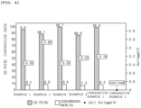
- Examples 1 to 6 maintained moisture wettability, resulting in improved work processability, and also had excellent effects in terms of carbon dioxide conversion rate, CO Faraday efficiency, and overvoltage. Meanwhile, it is determined that Comparative Example 2 using a separator including a porous structure layer containing polyethylene (PE) maintained moisture wettability, but when assembled to an electrochemical conversion cell and used, an overvoltage of 6 V or greater took place and a very inferior effect in terms of carbon dioxide conversion rate and CO Faraday efficiency was shown.
- PE polyethylene
- Comparative Example 3 has a structure in which an anion exchange membrane was impregnated in the porous structure layer, and in Comparative Example 3, the anion exchange membrane having ion conductivity was not in the form of a single layer and was impregnated and unevenly arranged in each pore, and thus the porous structure layer failed to maintain moisture wettability, and the separator was broken after 1 hour to 2 hours. In addition, it is determined that in the separator of Comparative Example 3, the movement of ions was not performed uniformly throughout the entire area of the anion exchange membrane, and thus the carbon monoxide Faraday efficiency was reduced.
Landscapes
- Chemical & Material Sciences (AREA)
- Chemical Kinetics & Catalysis (AREA)
- Engineering & Computer Science (AREA)
- Electrochemistry (AREA)
- Materials Engineering (AREA)
- Metallurgy (AREA)
- Organic Chemistry (AREA)
- Sustainable Development (AREA)
- Life Sciences & Earth Sciences (AREA)
- Manufacturing & Machinery (AREA)
- Sustainable Energy (AREA)
- General Chemical & Material Sciences (AREA)
- Crystallography & Structural Chemistry (AREA)
- Inorganic Chemistry (AREA)
- Composite Materials (AREA)
- Separation Using Semi-Permeable Membranes (AREA)
- Laminated Bodies (AREA)
- Cell Separators (AREA)
- Manufacture Of Porous Articles, And Recovery And Treatment Of Waste Products (AREA)
- Electrolytic Production Of Non-Metals, Compounds, Apparatuses Therefor (AREA)
Applications Claiming Priority (3)
| Application Number | Priority Date | Filing Date | Title |
|---|---|---|---|
| KR20220049687 | 2022-04-21 | ||
| KR1020230050853A KR20230150210A (ko) | 2022-04-21 | 2023-04-18 | 분리막 및 이를 포함하는 전기화학 전환 셀 |
| PCT/KR2023/005281 WO2023204587A1 (ko) | 2022-04-21 | 2023-04-19 | 분리막 및 이를 포함하는 전기화학 전환 셀 |
Publications (2)
| Publication Number | Publication Date |
|---|---|
| EP4491768A1 true EP4491768A1 (de) | 2025-01-15 |
| EP4491768A4 EP4491768A4 (de) | 2025-03-19 |
Family
ID=88420134
Family Applications (1)
| Application Number | Title | Priority Date | Filing Date |
|---|---|---|---|
| EP23792161.4A Pending EP4491768A4 (de) | 2022-04-21 | 2023-04-19 | Separator und elektrochemische umwandlungszelle damit |
Country Status (7)
| Country | Link |
|---|---|
| US (1) | US20260014527A1 (de) |
| EP (1) | EP4491768A4 (de) |
| JP (1) | JP2025514058A (de) |
| AU (1) | AU2023256210B2 (de) |
| CL (1) | CL2024003114A1 (de) |
| MA (1) | MA68017A1 (de) |
| WO (1) | WO2023204587A1 (de) |
Families Citing this family (2)
| Publication number | Priority date | Publication date | Assignee | Title |
|---|---|---|---|---|
| DK182057B1 (en) * | 2023-11-15 | 2025-06-18 | Stiesdal Hydrogen As | Porous hydrophilic separator, its method of production and an alkaline electrolyzer with such separator |
| JP2026055983A (ja) * | 2024-09-19 | 2026-04-01 | 株式会社東芝 | 電解装置 |
Family Cites Families (14)
| Publication number | Priority date | Publication date | Assignee | Title |
|---|---|---|---|---|
| JPS63118083A (ja) * | 1986-11-07 | 1988-05-23 | Asahi Glass Co Ltd | 複層隔膜を使用した電解方法 |
| US5180750A (en) * | 1988-07-29 | 1993-01-19 | Asahi Glass Company Ltd. | Anion exchanger |
| JPH0680799A (ja) * | 1992-08-28 | 1994-03-22 | Asahi Glass Co Ltd | 耐蝕性陰イオン交換膜 |
| JPH07258436A (ja) * | 1994-03-18 | 1995-10-09 | Asahi Glass Co Ltd | 複層イオン交換膜およびその製造方法 |
| JP3625633B2 (ja) * | 1997-12-08 | 2005-03-02 | ペルメレック電極株式会社 | ガス拡散電極構造体とその製造方法 |
| JP4447081B2 (ja) * | 1999-08-26 | 2010-04-07 | 川崎化成工業株式会社 | 多硫化物の製造方法 |
| US20110168381A1 (en) * | 2009-12-11 | 2011-07-14 | Hydration Systems, Llc | Osmotic Water Transfer System and Related Processes |
| WO2016039999A1 (en) * | 2014-09-08 | 2016-03-17 | 3M Innovative Properties Company | Ionic polymer membrane for a carbon dioxide electrolyzer |
| JP6672211B2 (ja) * | 2017-03-21 | 2020-03-25 | 株式会社東芝 | 二酸化炭素電解装置および二酸化炭素電解方法 |
| JP7273929B2 (ja) * | 2017-09-20 | 2023-05-15 | 株式会社東芝 | 電気化学反応装置および多孔質セパレータ |
| JP6965491B2 (ja) * | 2017-11-07 | 2021-11-10 | エルジー・ケム・リミテッド | 気体分離膜の製造方法およびこれにより製造された気体分離膜 |
| KR20190057786A (ko) * | 2017-11-20 | 2019-05-29 | 한국생산기술연구원 | 이산화탄소 전환용 전기화학 전지 |
| KR20190125822A (ko) | 2018-04-30 | 2019-11-07 | 광주과학기술원 | 음이온교환막 및 양이온교환막을 포함한 전기화학적 co2 전환 장치 및 이를 사용한 이산화탄소 전환방법 |
| WO2020032356A1 (ko) * | 2018-08-09 | 2020-02-13 | 한국에너지기술연구원 | 염도차 발전장치 |
-
2023
- 2023-04-19 MA MA68017A patent/MA68017A1/fr unknown
- 2023-04-19 AU AU2023256210A patent/AU2023256210B2/en active Active
- 2023-04-19 JP JP2024561651A patent/JP2025514058A/ja active Pending
- 2023-04-19 WO PCT/KR2023/005281 patent/WO2023204587A1/ko not_active Ceased
- 2023-04-19 US US18/854,769 patent/US20260014527A1/en active Pending
- 2023-04-19 EP EP23792161.4A patent/EP4491768A4/de active Pending
-
2024
- 2024-10-15 CL CL2024003114A patent/CL2024003114A1/es unknown
Also Published As
| Publication number | Publication date |
|---|---|
| WO2023204587A1 (ko) | 2023-10-26 |
| CL2024003114A1 (es) | 2025-02-21 |
| US20260014527A1 (en) | 2026-01-15 |
| MA68017A1 (fr) | 2025-11-28 |
| AU2023256210A1 (en) | 2024-10-17 |
| JP2025514058A (ja) | 2025-05-02 |
| EP4491768A4 (de) | 2025-03-19 |
| AU2023256210B2 (en) | 2026-02-26 |
Similar Documents
| Publication | Publication Date | Title |
|---|---|---|
| RU2709479C1 (ru) | Анод для электролиза водного раствора щелочи и способ изготовления анода для электролиза водного раствора щелочи | |
| US8383692B2 (en) | Method of activating boron nitride | |
| JP6049633B2 (ja) | ガス拡散電極 | |
| RU2361327C2 (ru) | Структура для газодиффузионных материалов и способ их получения | |
| EP3767009A1 (de) | Titanbasismaterial, verfahren zur herstellung eines titanbasismaterials, elektrode für wasserelektrolyse und wasserelektrolysevorrichtung | |
| EP4491768A1 (de) | Separator und elektrochemische umwandlungszelle damit | |
| KR102762559B1 (ko) | 수소 투과도 감소 표면층을 가지는 다공성 분리막 및 이의 제조방법 | |
| KR20040071755A (ko) | 연료 전지용 기체 확산 지지재 | |
| KR20230150210A (ko) | 분리막 및 이를 포함하는 전기화학 전환 셀 | |
| EP4130343A1 (de) | Titansubstrat, verfahren zur herstellung eines titansubstrats, elektrode für wasserelektrolyse und wasserelektrolysevorrichtung | |
| EP4060777B1 (de) | Polymerelektrolytmembran, verfahren zur herstellung der membran und brennstoffzelle mit dieser membran | |
| WO2023280600A1 (en) | A separator for alkaline water electrolysis | |
| CN118946689A (zh) | 分隔件和包括其的电化学转化电池 | |
| JPH09120827A (ja) | 固体高分子電解質型燃料電池 | |
| CA3247293A1 (en) | Separator and electrochemical conversion cell including the same | |
| EP4350048A2 (de) | Träger, elektrode, membranelektrodenanordnung, elektrochemische zelle, stapel und elektrolyseur | |
| JPH06342667A (ja) | 高分子型燃料電池 | |
| KR20240041149A (ko) | 전해조 분리막 제조방법 및 전해조 분리막 | |
| DE19815455A1 (de) | Kombination aus Elektrolyse- und Brennstoffzelle | |
| KR20250033049A (ko) | 전기분해 셀 및 이의 제조방법 | |
| DE29823321U1 (de) | Kombination aus Elektrolyse- und Brennstoffzelle | |
| KR20250172019A (ko) | 분리막, 이를 포함하는 전기분해 셀 및 전기분해 장치 | |
| KR20230168035A (ko) | 전해조 | |
| DE69129501T2 (de) | Katalytische metallenthaltende gasdiffusionselektrode mit hohem wirkungsgrad, herstellungsverfahren und zelle mit dieser elektrode | |
| EP4349480A1 (de) | Katalysator, verfahren zur herstellung des katalysators und zwischenprodukt |
Legal Events
| Date | Code | Title | Description |
|---|---|---|---|
| STAA | Information on the status of an ep patent application or granted ep patent |
Free format text: STATUS: THE INTERNATIONAL PUBLICATION HAS BEEN MADE |
|
| PUAI | Public reference made under article 153(3) epc to a published international application that has entered the european phase |
Free format text: ORIGINAL CODE: 0009012 |
|
| STAA | Information on the status of an ep patent application or granted ep patent |
Free format text: STATUS: REQUEST FOR EXAMINATION WAS MADE |
|
| 17P | Request for examination filed |
Effective date: 20241007 |
|
| AK | Designated contracting states |
Kind code of ref document: A1 Designated state(s): AL AT BE BG CH CY CZ DE DK EE ES FI FR GB GR HR HU IE IS IT LI LT LU LV MC ME MK MT NL NO PL PT RO RS SE SI SK SM TR |
|
| A4 | Supplementary search report drawn up and despatched |
Effective date: 20250219 |
|
| RIC1 | Information provided on ipc code assigned before grant |
Ipc: B01D 69/12 20060101ALI20250213BHEP Ipc: C25B 3/26 20210101ALI20250213BHEP Ipc: C25B 9/19 20210101ALI20250213BHEP Ipc: C25B 1/23 20210101ALI20250213BHEP Ipc: C25B 13/08 20060101ALI20250213BHEP Ipc: C25B 13/02 20060101AFI20250213BHEP |
|
| DAV | Request for validation of the european patent (deleted) | ||
| DAX | Request for extension of the european patent (deleted) | ||
| STAA | Information on the status of an ep patent application or granted ep patent |
Free format text: STATUS: EXAMINATION IS IN PROGRESS |
|
| 17Q | First examination report despatched |
Effective date: 20250922 |