EP4491877A2 - Rückschlagventil, vakuumgerät und vakuumpumpe - Google Patents
Rückschlagventil, vakuumgerät und vakuumpumpe Download PDFInfo
- Publication number
- EP4491877A2 EP4491877A2 EP24216474.7A EP24216474A EP4491877A2 EP 4491877 A2 EP4491877 A2 EP 4491877A2 EP 24216474 A EP24216474 A EP 24216474A EP 4491877 A2 EP4491877 A2 EP 4491877A2
- Authority
- EP
- European Patent Office
- Prior art keywords
- closing element
- mass
- check valve
- vacuum pump
- sealing seat
- Prior art date
- Legal status (The legal status is an assumption and is not a legal conclusion. Google has not performed a legal analysis and makes no representation as to the accuracy of the status listed.)
- Granted
Links
Images


Classifications
-
- F—MECHANICAL ENGINEERING; LIGHTING; HEATING; WEAPONS; BLASTING
- F04—POSITIVE - DISPLACEMENT MACHINES FOR LIQUIDS; PUMPS FOR LIQUIDS OR ELASTIC FLUIDS
- F04C—ROTARY-PISTON, OR OSCILLATING-PISTON, POSITIVE-DISPLACEMENT MACHINES FOR LIQUIDS; ROTARY-PISTON, OR OSCILLATING-PISTON, POSITIVE-DISPLACEMENT PUMPS
- F04C29/00—Component parts, details or accessories of pumps or pumping installations, not provided for in groups F04C18/00 - F04C28/00
- F04C29/12—Arrangements for admission or discharge of the working fluid, e.g. constructional features of the inlet or outlet
- F04C29/124—Arrangements for admission or discharge of the working fluid, e.g. constructional features of the inlet or outlet with inlet and outlet valves specially adapted for rotary or oscillating piston pumps
- F04C29/126—Arrangements for admission or discharge of the working fluid, e.g. constructional features of the inlet or outlet with inlet and outlet valves specially adapted for rotary or oscillating piston pumps of the non-return type
-
- F—MECHANICAL ENGINEERING; LIGHTING; HEATING; WEAPONS; BLASTING
- F04—POSITIVE - DISPLACEMENT MACHINES FOR LIQUIDS; PUMPS FOR LIQUIDS OR ELASTIC FLUIDS
- F04C—ROTARY-PISTON, OR OSCILLATING-PISTON, POSITIVE-DISPLACEMENT MACHINES FOR LIQUIDS; ROTARY-PISTON, OR OSCILLATING-PISTON, POSITIVE-DISPLACEMENT PUMPS
- F04C18/00—Rotary-piston pumps specially adapted for elastic fluids
- F04C18/02—Rotary-piston pumps specially adapted for elastic fluids of arcuate-engagement type, i.e. with circular translatory movement of co-operating members, each member having the same number of teeth or tooth-equivalents
- F04C18/0207—Rotary-piston pumps specially adapted for elastic fluids of arcuate-engagement type, i.e. with circular translatory movement of co-operating members, each member having the same number of teeth or tooth-equivalents both members having co-operating elements in spiral form
- F04C18/0215—Rotary-piston pumps specially adapted for elastic fluids of arcuate-engagement type, i.e. with circular translatory movement of co-operating members, each member having the same number of teeth or tooth-equivalents both members having co-operating elements in spiral form where only one member is moving
-
- F—MECHANICAL ENGINEERING; LIGHTING; HEATING; WEAPONS; BLASTING
- F04—POSITIVE - DISPLACEMENT MACHINES FOR LIQUIDS; PUMPS FOR LIQUIDS OR ELASTIC FLUIDS
- F04C—ROTARY-PISTON, OR OSCILLATING-PISTON, POSITIVE-DISPLACEMENT MACHINES FOR LIQUIDS; ROTARY-PISTON, OR OSCILLATING-PISTON, POSITIVE-DISPLACEMENT PUMPS
- F04C25/00—Adaptations of pumps for special use of pumps for elastic fluids
- F04C25/02—Adaptations of pumps for special use of pumps for elastic fluids for producing high vacuum
-
- F—MECHANICAL ENGINEERING; LIGHTING; HEATING; WEAPONS; BLASTING
- F04—POSITIVE - DISPLACEMENT MACHINES FOR LIQUIDS; PUMPS FOR LIQUIDS OR ELASTIC FLUIDS
- F04C—ROTARY-PISTON, OR OSCILLATING-PISTON, POSITIVE-DISPLACEMENT MACHINES FOR LIQUIDS; ROTARY-PISTON, OR OSCILLATING-PISTON, POSITIVE-DISPLACEMENT PUMPS
- F04C29/00—Component parts, details or accessories of pumps or pumping installations, not provided for in groups F04C18/00 - F04C28/00
- F04C29/06—Silencing
-
- F—MECHANICAL ENGINEERING; LIGHTING; HEATING; WEAPONS; BLASTING
- F16—ENGINEERING ELEMENTS AND UNITS; GENERAL MEASURES FOR PRODUCING AND MAINTAINING EFFECTIVE FUNCTIONING OF MACHINES OR INSTALLATIONS; THERMAL INSULATION IN GENERAL
- F16K—VALVES; TAPS; COCKS; ACTUATING-FLOATS; DEVICES FOR VENTING OR AERATING
- F16K1/00—Lift valves or globe valves, i.e. cut-off apparatus with closure members having at least a component of their opening and closing motion perpendicular to the closing faces
- F16K1/32—Details
- F16K1/34—Cutting-off parts, e.g. valve members, seats
- F16K1/36—Valve members
-
- F—MECHANICAL ENGINEERING; LIGHTING; HEATING; WEAPONS; BLASTING
- F16—ENGINEERING ELEMENTS AND UNITS; GENERAL MEASURES FOR PRODUCING AND MAINTAINING EFFECTIVE FUNCTIONING OF MACHINES OR INSTALLATIONS; THERMAL INSULATION IN GENERAL
- F16K—VALVES; TAPS; COCKS; ACTUATING-FLOATS; DEVICES FOR VENTING OR AERATING
- F16K15/00—Check valves
- F16K15/02—Check valves with guided rigid valve members
- F16K15/025—Check valves with guided rigid valve members the valve being loaded by a spring
- F16K15/026—Check valves with guided rigid valve members the valve being loaded by a spring the valve member being a movable body around which the medium flows when the valve is open
-
- F—MECHANICAL ENGINEERING; LIGHTING; HEATING; WEAPONS; BLASTING
- F16—ENGINEERING ELEMENTS AND UNITS; GENERAL MEASURES FOR PRODUCING AND MAINTAINING EFFECTIVE FUNCTIONING OF MACHINES OR INSTALLATIONS; THERMAL INSULATION IN GENERAL
- F16K—VALVES; TAPS; COCKS; ACTUATING-FLOATS; DEVICES FOR VENTING OR AERATING
- F16K27/00—Construction of housing; Use of materials therefor
- F16K27/02—Construction of housing; Use of materials therefor of lift valves
- F16K27/0209—Check valves or pivoted valves
-
- F—MECHANICAL ENGINEERING; LIGHTING; HEATING; WEAPONS; BLASTING
- F04—POSITIVE - DISPLACEMENT MACHINES FOR LIQUIDS; PUMPS FOR LIQUIDS OR ELASTIC FLUIDS
- F04C—ROTARY-PISTON, OR OSCILLATING-PISTON, POSITIVE-DISPLACEMENT MACHINES FOR LIQUIDS; ROTARY-PISTON, OR OSCILLATING-PISTON, POSITIVE-DISPLACEMENT PUMPS
- F04C2220/00—Application
- F04C2220/50—Pumps with means for introducing gas under pressure for ballasting
-
- F—MECHANICAL ENGINEERING; LIGHTING; HEATING; WEAPONS; BLASTING
- F04—POSITIVE - DISPLACEMENT MACHINES FOR LIQUIDS; PUMPS FOR LIQUIDS OR ELASTIC FLUIDS
- F04D—NON-POSITIVE-DISPLACEMENT PUMPS
- F04D19/00—Axial-flow pumps
- F04D19/02—Multi-stage pumps
- F04D19/04—Multi-stage pumps specially adapted to the production of a high vacuum, e.g. molecular pumps
Definitions
- the present invention relates to a check valve, in particular one for use in a vacuum device, in particular a vacuum pump, wherein the check valve comprises a passage for a fluid, a movable closing element and a sealing seat, wherein the closing element and the sealing seat are designed to correspond in such a way that the closing element blocks the passage when it is in contact with the sealing seat.
- the invention also relates to a vacuum device, a vacuum pump, a compressor and a scroll pump with such a check valve.
- Check valves are used in various vacuum devices, for example.
- a gas ballast valve in a vacuum pump can be equipped with an integrated check valve.
- a gas ballast valve typically serves the purpose of supplying a ballast gas, such as air or another gas or gas mixture, into a pump chamber of a vacuum pump. This serves, for example, to prevent condensation of the medium to be pumped by the vacuum pump or individual components thereof in order to protect the pump from corrosion and condensate accumulation.
- the supply of ballast gas can also serve, for example, to dilute the process gas, i.e. the medium to be pumped.
- a check valve typically opens and closes due to a pressure difference across the valve, possibly depending on a spring force of a spring which biases the closing element against the seal seat.
- this noise depends, among other things, on the speed of the closing element, which depends on the pressure conditions and, if applicable, on a spring force. If the pressure on at least one side of the valve changes frequently or continuously, then the valve is also actuated frequently and thus the closing element hits the seal seat frequently, with the corresponding noise being generated.
- the problem described above is particularly relevant for vacuum devices and in particular for vacuum pumps.
- this particularly affects an evacuation process, i.e. the period in which an area to be evacuated is reduced from an initial pressure, for example atmospheric pressure, to a desired pressure, namely a vacuum pressure.
- the pressure changes continuously.
- the pressure often pulsates. This is more or less pronounced depending on the underlying pumping principle and is particularly true if the check valve is directly connected to a pump chamber of a vacuum pump.
- the locking element is movable due to the connection together with the mass element. Due to the additional mass element, the total mass of the movable assembly consisting of the closing element and the mass element. The inertia is increased accordingly. This means that the closing element only assumes lower speeds under given pressure conditions and consequently also has a lower speed when it hits the seal seat. This results in lower noise emissions.
- the mass element is basically designed separately from the closing element, even if it is connected to it. This means that the closing element and the mass element are manufactured separately as different parts and then connected to each other. In principle, a material connection, such as a welded connection, can also be considered.
- the mass element serves the purpose of increasing the total mass of the assembly consisting of the closing element and the mass element. For example, it is advantageous if the mass element has at least the same mass, i.e. the same weight, as the closing element. It is particularly advantageous if the mass element has at least 1.5 times the mass, more preferably at least twice the mass, compared to the closing element.
- the closing element basically has a mass ms which can be, for example, at least 1.5 g, preferably at least 2.0 g and/or at most 3.0 g, preferably at most 2.5 g.
- the mass element basically has a mass m M which can preferably be at least 2.0 g, particularly preferably at least 3.0 g, and/or at most 6.0 g, particularly preferably at most 4.0 g.
- the additional mass element offers the advantageous possibility of making the mass element and the closing element from different materials.
- the materials of the two elements can be specifically selected with regard to the task of the respective element.
- a material can be selected for the closing element which, in cooperation with a sealing seat, allows for a high level of tightness and is particularly easy to manufacture.
- the material of the mass element can be selected in particular according to its density, since the mass element should be as heavy as possible.
- the mass element and the closing element have different materials, whereby the material of the mass element has a higher density than the material of the closing element.
- the elements insofar as it is said that they "have” a material, can also be made from this material and/or exclusively have the material.
- the material of the mass element has a density that is at least twice as high, more preferably at least three times as high, as the density of the material of the closing element.
- the locking element can be made from plastic, for example. This makes it easy to manufacture, but it can still achieve good sealing. In principle, however, the locking element can also be made from metal, for example. According to a particularly advantageous embodiment, the material of the locking element is fluororubber or FKM.
- the mass element can preferably be made of metal. Steel is particularly suitable because it has a relatively high density, is inexpensive and readily available and is easy to work with.
- the mass element can also be made of plastic, for example, preferably a high-density plastic.
- the sealing seat can be made of metal or plastic, for example.
- the mass element is firmly connected to the closing element.
- the closing element and the mass element can therefore only be moved together and uniformly. This allows for a simple structure on the one hand and effective noise reduction on the other.
- an elastic and/or damping connection can also be provided. This can further reduce the speed of the closing element.
- the mass element acts like a damper.
- the mass element can be connected to the closing element, for example, by a force-fitting, a form-fitting and/or a material-fitting connection.
- the connection can basically be detachable or non-detachable.
- Exemplary embodiments include that the mass element is connected to the closing element by a screw connection, a snap connection, a press connection, by barbs and/or a cant.
- Simple Solutions include, for example, that the mass element is screwed or plugged into the locking element, or vice versa.
- the closing element can be pre-tensioned against the sealing seat by means of a spring, for example.
- the spring can preferably be a helical compression spring.
- the spring has in particular a spring constant k which is preferably at least 0.15 N/mm, more preferably at least 0.2 N/mm, and/or at most 4 N/mm, more preferably at most 3.0 N/mm.
- the spring can be made of steel, for example.
- F ext denotes the excitation force. This is defined here by the pressure difference across the valve in relation to the cross-sectional area.
- F F denotes the restoring force of the spring and is, in the simplest case, proportional to the deflection.
- F D denotes the damping force, which is in particular proportional to the speed of the deflection. In the simplest case, this records a damping inherent in the system, for example a damping that results from the friction between the closing element and/or mass element on the one hand and the fluid flowing through the valve on the other.
- a real spring also has a certain inherent damping. However, the damping inherent in the system is often small and can therefore be neglected, at least in rough calculations.
- the mass of the oscillating system cannot oscillate freely because the seal seat forms a stop in the path of movement of the mass.
- damping is neglected, although similar relationships can be demonstrated for the case with damping. This applies in particular to the case of low damping, as can be expected in the context of a check valve, especially if the medium flowing through the check valve is gaseous. Furthermore, this applies particularly in a vacuum device, since pressures of less than 1 atm are usually present here.
- ⁇ may be unknown or difficult to determine. Nevertheless, advantageous values for k/m can be estimated, which are likely to maintain a supercritical range.
- the mass element and the closing element together have a mass m, the spring having a spring constant k and the ratio k/m being at most 110,000 s -2 , preferably at most 70,000 s -2 , particularly preferably at most 50,000 s -2 .
- these value ranges have proven to be advantageous for vacuum devices and particularly preferably for vacuum pumps, in particular scroll pumps, and compressors.
- the value ranges apply with particular advantage in the case where the check valve is arranged to control the flow through a gas ballast valve.
- the mass element and the closing element together with the spring form an oscillatory system, wherein the system is dimensioned such that it is operated in the supercritical range during operation of the valve.
- the closing element and/or the sealing seat can also be advantageous for the closing element and/or the sealing seat to have a spherical or conical contact surface for contact with the sealing seat or the closing element.
- the contact surface is ring-shaped and encloses the passage.
- the closing element the surface area which, in the locked state, is in direct contact with the corresponding surface of the sealing seat is also ring-shaped.
- a surface facing the sealing seat can be spherical in the closing element and, in particular, closed in cross-section and/or not ring-shaped.
- the closing element has a contact surface for contact with the sealing seat and the mass element is arranged on a side of the closing element facing away from the contact surface and/or is connected to it.
- the mass element can be arranged in the interior of a spring, in particular a helical spring. This allows a particularly compact arrangement.
- the mass element can, for example, have a connecting section and/or a mass section.
- the mass section can preferably have a mass that is at least twice as high as the connecting section.
- the connecting section and the mass section can, for example, be separated from one another by a step.
- the connecting section can, for example, extend into a recess in the closing element.
- the connecting section can, for example, be screwed into the recess or inserted into it.
- a connecting section of the mass element and/or the closing element can, for example, have at least one elevation which acts as a barb
- at least one elevation which acts as a barb
- several such elevations can be provided.
- the at least one elevation can preferably be formed all the way around.
- the mass element can be a one-piece element or consist of several components.
- the additional mass element increases the mass and thus the inertia of the assembly moving in the check valve.
- This inertia also affects the gas flow, i.e. the amount of gas that can pass through the check valve per unit of time at given pressure conditions.
- This connection can also be used to adjust the gas flow as desired.
- the gas flow is also significantly dependent on the force of any spring present in the check valve.
- a vacuum device in particular a vacuum pump, preferably a scroll pump, or a compressor, with a check valve of the type described above.
- a vacuum pump or a compressor which has a gas ballast valve can advantageously be equipped with a check valve of the type described above, wherein the check valve is arranged in particular to control the flow through the gas ballast valve.
- the check valve allows the gas flow through the gas ballast valve in one direction and blocks the gas flow in the opposite direction.
- the check valve is preferably arranged in such a way that gas is prevented from escaping from the vacuum pump or the compressor, in particular from a pump chamber, while ballast gas can be introduced.
- the check valve can, for example, be integrated into the gas ballast valve or installed upstream or downstream of it.
- the vacuum pump or compressor preferably comprises a pump body, the inside of which delimits a pump chamber and on the outside of which a gas ballast valve is arranged for controlling the supply of a ballast gas into the pump chamber.
- the invention further comprises a vacuum pump, in particular a scroll pump, or a compressor with a gas ballast valve and a check valve, in particular one of the type described above, wherein the check valve is arranged to control the flow through the gas ballast valve, wherein the check valve comprises a passage for a fluid as well as a movable closing element and a sealing seat, wherein the closing element and the sealing seat are designed to correspond in such a way that the closing element blocks the passage when it is in contact with the sealing seat, wherein the check valve has a spring with a spring constant k which prestresses the closing element against the sealing seat, wherein the check valve has a movable mass m which is at least partially formed by the closing element, and wherein an oscillatory system formed by the movable mass and the spring is dimensioned such that it is operated in the supercritical range, and/or wherein k/m ⁇ 110,000 s -2 .
- a fundamental idea of the invention is that the mass m that can be moved in the check valve should be particularly large, in particular in relation to a spring constant k, if a spring is present. This brings about an advantageous reduction in noise emissions during operation using simple means. As far as the check valve in general is concerned, this idea is implemented - as described above - by an additional mass element. In principle, however, the closing element itself can also have a high mass in order to reduce noise emissions. to reduce. In the specific context of a vacuum pump with a gas ballast valve, it has been shown to be advantageous if k/m ⁇ 110,000 s -2 , preferably k/m ⁇ 70,000 s -2 , particularly preferably k/m ⁇ 50,000 s -2 . In the context of the vacuum pump mentioned, this thus represents the realization of the underlying idea that a high mass, particularly in relation to the spring constant k, should be aimed for.
- the invention is also fundamentally directed to a method, not currently separately claimed, for producing a check valve of the type described above and/or a vacuum device with such a valve, wherein the mass element and the closing element are produced separately from one another and are subsequently connected.
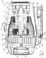
- the Fig. 1 shows a vacuum pump designed as a scroll pump 20.
- This comprises a first housing element 22 and a second housing element 24, the second housing element 24 having a pump-active structure, namely a spiral wall 26.
- the second housing element 24 thus forms a fixed spiral component of the scroll pump 20.
- the spiral wall 26 interacts with a spiral wall 28 of a movable spiral component 30, the movable spiral component 30 being eccentrically excited via an eccentric shaft 32 to generate a pumping effect.
- a gas to be pumped is conveyed from an inlet 31, which is defined in the first housing element 22, to an outlet 33, which is defined in the second housing element 24.
- the eccentric shaft 32 is driven by a motor 34 and supported by two roller bearings 36. It comprises an eccentric pin 38 arranged eccentrically to its axis of rotation, which transmits its eccentric deflection to the movable spiral component 30 via a further roller bearing 40.
- spiral component 30 is also Fig. 1 left-hand end of a bellows 42, the right-hand end of which is attached to the first housing element 22. The left-hand end of the bellows 42 follows the deflection of the movable spiral component 30.
- the scroll pump 20 comprises a fan 44 for generating a cooling air flow.
- An air guide hood 46 is provided for this cooling air flow, to which the fan 44 is also attached.
- the air guide hood 46 and the housing elements 22 and 24 are shaped in such a way that the cooling air flow essentially flows around the entire pump housing and thus achieves good cooling performance.
- the scroll pump 20 further comprises an electronics housing 48 in which a control device and power electronics components for driving the motor 34 are arranged.
- the electronics housing 48 also forms a base for the pump 20. Between the electronics housing 48 and the first housing element 22, a channel 50 is visible through which an air flow generated by the fan 44 is guided along the first housing element 22 and also along the electronics housing 48, so that both are effectively cooled.
- the electronics housing 48 is in Fig. 2 illustrated in more detail. It comprises several separate chambers 52. Electronic components can be encapsulated in these chambers 52 and are thus advantageously shielded. Preferably, the smallest possible amount of encapsulation material can be used when encapsulating the electronic components. For example, the encapsulation material can first be introduced into the chamber 52 and then the electronic component can be pressed in.
- the chambers 52 can be designed in such a way that different variants of the electronic components, in particular different assembly variants of a circuit board, can be arranged in the electronic housing 48 and/or encapsulated. For certain variants, individual chambers 52 can also remain empty, i.e. no electronic component In this way, a so-called modular system for different pump types can be implemented in a simple manner.
- the potting material can in particular be designed to be heat-conducting and/or electrically insulating.
- a plurality of walls or ribs 54 are formed on the rear side of the electronics housing 48, which define a plurality of channels 50 for conducting a cooling air flow.
- the chambers 52 also enable particularly good heat dissipation from the electronic components arranged in them, in particular in conjunction with a heat-conducting potting material, and towards the ribs 54. The electronic components can thus be cooled particularly effectively and their service life is improved.
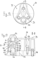
- FIG. 3 the scroll pump 20 is shown as a whole in perspective, but the air guide hood 46 is hidden so that the fixed spiral component 24 and the fan 44 are visible.
- the fixed spiral component 24 has a plurality of recesses 56 arranged in a star shape, each of which defines ribs 58 arranged between the recesses 56.
- the cooling air flow generated by the fan 44 leads through the recesses 56 and past the ribs 58 and thus cools the fixed spiral component 24 particularly effectively.
- the cooling air flow first flows around the fixed spiral component 24 and only then around the first housing element 22 or the electronics housing 48. This arrangement is particularly advantageous because the pump-active area of the pump 20 develops a lot of heat due to the compression during operation and is therefore primarily cooled here.
- the pump 20 comprises a pressure sensor 60 integrated therein. This is arranged inside the air guide hood 46 and screwed into the fixed spiral component 24.
- the pressure sensor 60 is connected to the electronics housing 48 and a control device arranged therein via a cable connection (only partially shown).
- the pressure sensor 60 is integrated into the control of the Scroll pump 20.
- the motor 34 which is in Fig. 1 visible, depending on a pressure measured by the pressure sensor 60.
- the high vacuum pump can only be switched on if the pressure sensor 60 measures a sufficiently low pressure. In this way, the high vacuum pump can be protected from damage.
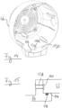
- Fig. 4 shows the pressure sensor 60 and its arrangement on the fixed spiral component 24 in a cross-sectional view.
- a channel 62 is provided for the pressure sensor 60, which here opens into a non-pumping outdoor area between the spiral walls 26 and 28 of the fixed or movable spiral components 24 and 30.
- the pressure sensor thus measures a suction pressure of the pump.
- a pressure between the spiral walls 26 and 28 in a pumping active area can also be measured.
- intermediate pressures can also be measured, for example.
- the pressure sensor 60 allows, for example by determining compression, in particular to detect a state of wear of the pump-active components, in particular of a sealing element 64 also referred to as a tip seal.
- the measured intake pressure can also be used to regulate the pump (including pump speed).
- an intake pressure can be specified by software and an intake pressure can be set by varying the pump speed. It is also conceivable that, depending on the measured pressure, a pressure increase due to wear can be compensated by increasing the speed. In this way, a tip seal change can be postponed or longer change intervals can be implemented.
- the data from the pressure sensor 60 can therefore generally be used, for example, to determine wear, to control the pump in a given situation, to control the process, etc.
- the pressure sensor 60 can, for example, be provided optionally. Instead of the pressure sensor 60, for example, a blind plug can be provided to close the channel 62. A pressure sensor 60 can then, for example, be retrofitted if required. Particularly with regard to retrofitting, but also generally advantageous, it can be provided that the pressure sensor 60 is automatically recognized when connected to the control device of the pump 20.
- the pressure sensor 60 is arranged in the cooling air flow of the fan 44. This also advantageously cools it. This also means that no special measures need to be taken to increase the temperature resistance of the pressure sensor 60 and, consequently, a cost-effective sensor can be used.
- the pressure sensor 60 is arranged in particular such that the external dimensions of the pump 20 are not increased by it and the pump 20 consequently remains compact.
- the movable spiral component 30 is shown in different views.
- the spiral structure of the spiral wall 28 is particularly clearly visible.
- the spiral component 30 comprises a base plate 66 from which the spiral wall 28 extends.
- a side of the base plate 66 facing away from the spiral wall 28 is in Fig. 6 visible.
- the base plate includes, among other things, several mounting recesses, for example for mounting the bearing 40 and the bellows 42, which are in Fig. 1 are visible.
- retaining projections 68 are provided, spaced apart over the circumference of the base plate 66 and evenly distributed over the circumference.
- the retaining projections 68 extend radially outwards. In particular, the retaining projections 68 all have the same radial height.
- a first intermediate section 70 of the circumference of the base plate 66 extends between two of the holding projections 68.
- This first intermediate section 70 has a greater radial height than a second intermediate section 72 and than a third intermediate section 74.
- the first intermediate section 70 is arranged opposite an outermost 120° section of the spiral wall 28.
- the base plate 66 and the spiral wall 28 are preferably manufactured together from a solid material, i.e. the spiral wall 28 and the base plate 66 are formed as one piece.
- the spiral component 30 can be clamped directly to the holding projections 68.
- the Fig. 6 shown side of the base plate 66 are machined, in particular the fastening recesses are made.
- the spiral wall 28 can also be machined from the solid material within the scope of this clamping.
- the spiral component 30 can be clamped, for example, with a clamping device 76, as shown in Fig. 7
- a clamping device 76 has a hydraulic three-jaw chuck 78 for direct contact with the three retaining projections 68.
- the clamping device 76 has a continuous recess 80 through which a tool access to the spiral component 30, in particular to the Fig. 6 shown side thereof.
- machining operations can be carried out from both sides during clamping, in particular at least a finishing machining of the spiral wall 28 and an introduction of fastening recesses.
- the contour of the retaining projections 68 and the clamping pressure of the clamping device 76 are preferably selected so that no critical deformations of the spiral component 30 occur.
- the three retaining projections 68 are preferably selected so that the external dimension, i.e. the maximum diameter of the spiral component 30, is not increased. This means that material and machining volume can be saved.
- the retaining projections 68 are in particular designed and/or arranged at such an angular position that the screw connection of the corrugated bellows 42 is accessible.
- the number of screw connection points of the corrugated bellows 42 is preferably not equal to the number of retaining projections 68 on the movable spiral component 30.
- balancing weights 82 are attached to compensate for any imbalance of the excited system.
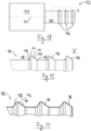
- the area of the Fig. 1 right-hand balance weight 82 is in Fig. 8 shown enlarged.
- the balancing weight 82 is screwed to the eccentric shaft 32.
- FIG. 9 A similar image section is in Fig. 9 for another scroll pump, preferably of the same series as pump 20 of the Fig. 1
- the Fig. 9 The underlying pump has different dimensions and therefore requires a different balancing weight 82.
- the eccentric shafts 32, the balancing weights 82 and the housing elements 22 are dimensioned such that only a specific type of the two types of balancing weights 82 shown can be mounted on the eccentric shaft 32 at the respective mounting position shown.
- the balance weights 82 are in the Fig. 8 and 9 together with certain dimensions of the installation space provided for it, in order to clarify that the balancing weight 82 of the Fig. 9 not on the eccentric shaft 32 can be mounted and vice versa. It is understood that the dimensions given are purely examples.
- the balancing weight 82 of the Fig. 8 is shorter in the corresponding direction, namely 9 mm long, so it can be installed without any problems.
- the balance weight 82 of the Fig. 9 has a longitudinal extension of 11 mm measured from the mounting hole.
- the balancing weight 82 of the Fig. 9 not on the eccentric shaft 32 of the Fig. 8 cannot be mounted because the shaft shoulder 86 collides with the balance weight 82 during an attempted assembly or because the balance weight 82 of the Fig. 9 not fully in contact with the eccentric shaft 82 of the Fig. 8 Because the balance weight 82 of the Fig.
- Fig. 9 The distance in the longitudinal direction between the mounting hole 84 and a housing shoulder 88 is 17.5 mm.
- the balancing weight 82 of the Fig. 8 With its extension of 21.3 mm, when inserting the eccentric shaft 32, the Fig. 9 collide with the housing shoulder 88, so that complete assembly would not be possible. Incorrect assembly is possible at first, but is reliably detected. If the balancing weight 82 of the Fig. 8 on the eccentric shaft 32 of the Fig. 9 the extension of 21.3 mm would collide with the shaft shoulder 86, which is arranged only at a distance of 13.7 mm from the mounting hole 84.
- the balancing weights 82 in particular a motor-side balancing weight 82, are generally designed in such a way that confusion of the balancing weight with those of other sizes is avoided during assembly and/or servicing.
- the balancing weights are preferably fastened using through-bolts. Similar balancing weights of different pump sizes are in particular designed in such a way that installation of the wrong balancing weight is prevented due to adjacent steps on the shaft, the positions of the thread and through-hole of the balancing weight and steps within the housing.
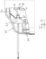
- FIG. 10 and 11 A gas ballast valve 90 of the scroll pump 20 is shown. This is also shown in the overall view of the pump 20 in Fig. 3 visible and arranged on the fixed spiral component 24.
- the gas ballast valve 90 comprises an actuating handle 92. This comprises a plastic body 94 and a base element 96, which is preferably made of stainless steel.
- the base element 96 comprises a through-hole 98, which is provided on the one hand for connecting and introducing a ballast gas and on the other hand comprises a check valve 100.
- the hole 98 is also closed in the illustrations by means of a plug 102.
- a filter can also be provided, for example, wherein the ballast gas can preferably be air and enters the valve 90 directly via the filter.
- the operating handle 92 is attached to a rotatable element 106 of the valve 90 by means of three fastening screws 104, which are arranged in a respective bore 108 and of which in the selected sectional view of the Fig. 11 only one is visible.
- the rotatable element 106 is rotatably attached to the second housing element 24 by means of a fastening screw (not shown) which runs through a bore 110.
- a torque applied manually to the operating handle 92 is transmitted to the rotatable element 106, thus rotating it.
- the bore 98 thus comes into communication with the interior of the housing.
- Three switching positions are provided for the valve 90, namely the Fig. 10 shown, which is a locked position, and a position rotated to the right and to the left, in which the bore 98 is in communication with different areas of the interior of the housing.
- the holes 108 and 110 are closed by a cover 112.
- the sealing effect of the gas ballast valve 90 is based on axially pressed O-rings. When the valve 90 is actuated, a relative movement is exerted on the O-rings. If contaminants, such as particles, get onto the surface of an O-ring, this poses the risk of premature failure.
- the cover 112 prevents contaminants and the like from penetrating the screws of the handle 92.
- This cover 112 is attached via an interference fit of three centering elements. Specifically, the cover 112 has a plug-in pin (not shown) for each hole 108, with which the cover 112 is held in the holes 108.
- the holes 108 and 110 and the fastening screws arranged therein are thus protected from contamination.
- the fastening screw (not shown) arranged in the hole 110 which allows a rotary movement, the ingress of contamination into the valve mechanism can be effectively minimized and the service life of the valve can thus be improved.
- the plastic handle with overmolded stainless steel base ensures good corrosion resistance and low manufacturing costs. Furthermore, the The plastic of the handle is cooler due to the limited heat conduction and is therefore easier to use.
- a speed control is preferably provided.
- the fan is controlled by means of PWM depending on the power consumption and temperature of the power module, which is housed in the electronics housing 48, for example.
- the speed is set in line with the power consumption. However, control is only permitted when the module temperature is above 50 °C. If the pump enters temperature ranges of possible derating (temperature-related power reduction), the max. fan speed is automatically controlled. This control makes it possible to achieve a minimum noise level when the pump is cold, to ensure a low noise level at final pressure or at low load - corresponding to the pump noise, to achieve optimal cooling of the pump with a low noise level at the same time, and to ensure the max. cooling capacity before a temperature-related power reduction.
- the maximum fan speed can be adjusted, especially depending on the situation. For example, if a system has a high tolerance to water vapor, it may be useful to reduce the maximum fan speed.
- FIG. 12 the movable spiral component 30 is partially and opposite Fig. 5 enlarged.
- a sectional view of the spiral component 30 along the Fig. 12 indicated line A:A is in Fig. 13 shown schematically and not to scale.
- the spiral wall 28 has, at its end facing away from the base plate 66 and facing a base plate of the fixed spiral component 24 (not shown here), a groove 114 for inserting a sealing element (also not shown here). 64, namely a so-called tip seal.
- the arrangement in the operating state is shown in Fig. 4 clearly visible.
- the groove 114 is delimited to the outside and to the inside by two opposite side walls, namely by an inner side wall 116 and an outer side wall 118.
- the outer side wall 118 is thicker than the inner side wall 116 in the first spiral section 120 and thicker than both side walls 116 and 118 in another, second spiral section 122.
- the first spiral section 120 extends from Fig. 12 indicated place to the outer end of the spiral wall 28, as is also the case in Fig. 5 is indicated.
- the first spiral section 120 extends here, for example, over approximately 163°.
- the first spiral section 120 forms an outer end section of the spiral wall 28.
- the first spiral section 120 is arranged at least partially, in particular completely, in a non-pumping area of the spiral wall 28.
- the first spiral section 120 can at least substantially completely fill the non-pumping area of the spiral wall 28.
- the first intermediate section 70 between two retaining projections 68 which has a greater radial height than other intermediate sections 72 and 74, can preferably be arranged opposite the first spiral section 120.
- An imbalance introduced by the thicker side wall 118 can thus be compensated by the greater weight of the first intermediate section 70.
- the movable spiral component should generally preferably have a low dead weight.
- the spiral walls are therefore generally very thin. Furthermore, thinner walls result in smaller pump dimensions (significant outer diameter).
- the side walls of the tip seal groove are therefore particularly thin.
- the ratio of the tip seal wall thickness to the total spiral wall thickness is, for example, a maximum of 0.17.
- the spiral wall tip is very sensitive to impacts during handling, such as during assembly or when changing the tip seal. Light impacts, e.g. during transport, can push the side wall of the groove inwards so that the tip seal can no longer be installed.
- the groove has an asymmetrical wall thickness, in particular a local thickening of the spiral wall towards the outside. This area is preferably not pump-active and can therefore be manufactured with a larger tolerance.
- the one-sided thickening on the, particularly the last half turn significantly reduces damage. At other parts of the component, thickening of the spiral wall is preferably not necessary, since the wall is protected by protruding elements of the component.
- the in Fig. 1 The air guide hood 46 shown defines an air flow, as indicated by a dashed arrow 124.
- the fan 44 is connected to a control device in the electronics housing 48 via a cable (not shown) which runs through the air guide hood 46, and via a plug connection.
- This comprises a socket 126 and a plug 128.
- the socket 126 is mounted on the electronics housing 48 and/or attached to a circuit board arranged in the electronics housing 48.
- the socket 126 is also provided, for example, in the Fig. 2 and 3 visible.
- the connector 128 is connected to the fan 44 via the cable not shown.
- the plug connection 126, 128 is separated from the air flow 124 by a partition 130.
- the air flow 124 which may contain dust or similar contaminants, is thus kept away from the plug connection 126, 128.
- the plug connection 126, 128 itself is protected and, on the other hand, it prevents dirt from entering the electronics housing 48 through the opening provided for the socket 126 and reaching the control device and/or power electronics.
- the air guide hood 46 is in Fig. 14 shown separately and in perspective. Among other things, the partition wall 130 with the space defined behind it for the connector 128 is visible.
- the partition wall 130 comprises a recess 132, designed here as a V-shaped notch, for passing a cable from the connector 128 to the fan 44.
- the partition 130 ensures that the air drawn in does not reach the electronics via the opening in the connector 126, 128.
- the cable of the fan is guided laterally through the partition 130 through the V-shaped notch 132.
- the notch 132 has a lateral offset to the connector 126, 128, which creates a labyrinth effect and thus further reduces the leakage of cooling air to the connector 126, 128.
- a partition 130 within the air guide hood 46 also improves the air flow into the channel 50 between the electronics housing 48 and the pump housing 22. There is less turbulence and back pressure for the fan 44.
- the Fig. 15 shows a contact area between the first housing element 22 and the second housing element or fixed spiral component 24 in a schematic sectional view.
- the second housing element 24 is partially inserted into the first housing element 22 with a transition fit 134.
- a seal is provided by means of an O-ring 136.
- the transition fit 134 also serves, for example, to center the second housing element 24 relative to the first housing element 22.
- a forcing thread 138 is provided.
- a second forcing thread can also be provided at least substantially radially opposite.
- the fastening screws 142 provided for fastening the second housing element 24 to the first housing element 22 can be used for pressing, as shown for example in the Fig. 1 and 3
- the forcing thread 138 preferably has the same type of thread as the fastening thread provided for the fastening screws 142.
- a countersink 140 is provided on the second housing element 22, which is associated with the forcing thread 138. If abrasion particles are discharged when the screw is screwed into the forcing thread 138, they collect in the countersink 140. This prevents such abrasion particles from, for example, preventing the housing elements 22 and 24 from completely engaging one another.
- the air guide hood 46 has at least one, in particular additional, Fig. 14 shown dome 144, which only allows the air guide hood 46 to be mounted when the screws used for forcing, in particular the fastening screws 142, have been removed again.
- the air guide hood 46 with the dome 144 is designed in such a way that it would collide with a screw head of a forcing screw that might be screwed into the forcing thread 138, so that the air guide hood 46 could not be fully mounted.
- the air guide hood 46 can only be mounted when the forcing screws are completely removed.
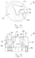
- the Fig. 16 and 17 show a gas ballast valve 90, which is similar to that of the Fig. 10 and 11 and can preferably be arranged on a scroll pump, e.g. the scroll pump 20.
- the reference numerals are assigned accordingly and reference is made to the above explanations.
- the gas ballast valve 90 is shown without a cover 112 as described above. It is understood that such a cover can also be used here.
- the check valve 100 has a passage 146 for a fluid, here for the ballast gas. This is releasably closed with a plug 102.
- the check valve 100 comprises a movable closing element 148 and a sealing seat 150.
- the movable closing element 148 and the sealing seat 150 are designed to correspond in such a way that the closing element 148 blocks the passage 146 when it is - as in Fig. 17 shown - is in contact with the sealing seat 150.
- the contact surfaces of the closing element 148 and the sealing seat 150 are spherical.
- the closing element 148 is pre-tensioned against the sealing seat 150 by means of a spring 152.
- the spring 152 is designed here as a helical compression spring. It is supported on the one hand on the rotatable element 106 and on the other hand rests against the closing element 148.
- the closing element 148 extends with a spring mandrel section 154 into an inner region of the spring 152. This serves in particular to precisely guide the closing element 148 in relation to the spring 152.
- the mass element 152 is arranged at least partially in the inner region of the spring 152, which enables a compact construction.
- the check valve 100 further comprises a mass element 156, which is firmly connected to the closing element 148. While the closing element 148 is made of plastic here, for example, the mass element 156 is made of metal, preferably steel, for example.
- the mass element 156 thus gives the movable assembly consisting of the closing element 148 and the mass element 156 a significantly greater mass than the closing element 148 would have on its own. This assembly therefore has a high inertia, which, as described above, leads to a reduction in noise emissions during operation of the gas ballast valve 90 in a vacuum device, in particular a vacuum pump, preferably a scroll pump.
- the mass element 156 comprises a mass section 158, which is designed to be as large as possible in order to achieve a high mass.
- the mass element 156 comprises a connecting section 160, which is designed to establish a connection to the closing element 148.
- the mass section 158 and the connecting section 160 are separated from one another by a shoulder 162.
- connection between the mass element 156 and the closing element 148 is designed in such a way that the connecting section 160 of the mass element 156 is inserted into a recess 164 of the closing element 148.
- the connecting section 160 has several elevations 166 which act as barbs.
- the elevations 166 will be discussed below with reference to the Fig. 18 to 20 discussed in more detail below.
- the connecting section 160 could also have a thread and be screwed into the closing element 148.
- the mass element 156 is arranged on a side of the closing element 148 which faces away from the contact surface of the closing element 148 for contact with the sealing seat 150.
- the mass element 156 could also be arranged starting from the closing element 148 in Fig. 17 extend upwards, whereby the connecting means would have to be adapted accordingly.
- the mass element 156 can therefore, for example, be in a locking direction, which Fig. 17 from bottom to top, in front of the closing element 148, as shown in Fig. 17 is the case, and/or also in the locking direction behind the locking element 148.
- the mass element 156 could also be completely integrated into the locking element 148.
- Fig. 18 1 shows an exemplary embodiment of a mass element 156 in more detail.
- the mass element 156 comprises a mass section 158 and a connecting section 160.
- the mass section 158 and the connecting section 160 are essentially cylindrical.
- the mass element 156 can be, for example, a turned part, ie a component produced by turning.
- the connecting section 160 is equipped with circumferential elevations 166 which, when connected to a closing element 148, form barbs and hold the connecting section 160 in a corresponding recess 164 of the closing element 148.
- the recess 164 can, for example, have preformed circumferential recesses corresponding to the elevations 166.
- the elevations 166 can partially elastically deform the material of the closing element 148 when the connecting section 160 is inserted into the recess 164 and then hold it in the recess 164 by elastic forces, the shape of the elevations 166 forming an obstacle to removing the connecting section 160 from the recess 164.
- Fig. 18 In the embodiment shown, three elevations 166 are provided. This number has proven to be particularly advantageous with regard to the strength of the connection. However, more or fewer elevations can also be provided, for example.
- FIG. 18 A sub-area X is marked, which in Fig. 19 is shown enlarged.
- the shape of the elevations 166 is clearly visible here.
- the three elevations 166 are essentially identical, which is why the shape can only be determined based on the Fig. 19 left elevation 166 is illustrated in more detail.
- the elevation 166 comprises a curve 168, an annular surface 170, which is perpendicular to the Fig. 18 indicated cylinder axis 172, a curve 174, a conical section 176 and a further curve 178.
- the curves can in principle be omitted.
- a connecting section 160 is shown in a representation similar to that of the Fig. 19
- three elevations 166 are planned, which those of Fig. 19
- the difference to be emphasized here is that instead of a surface 170 perpendicular to the cylinder axis 172, a further conical section 180 is provided. This is conical in the opposite direction to the conical section 176.
Landscapes
- Engineering & Computer Science (AREA)
- General Engineering & Computer Science (AREA)
- Mechanical Engineering (AREA)
- Applications Or Details Of Rotary Compressors (AREA)
- Check Valves (AREA)
- Rotary Pumps (AREA)
Abstract
Description
- Die vorliegende Erfindung betrifft ein Rückschlagventil, insbesondere ein solches für den Einsatz in einem Vakuumgerät, insbesondere einer Vakuumpumpe, wobei das Rückschlagventil einen Durchgang für ein Fluid, ein bewegliches Schließelement und einen Dichtungssitz umfasst, wobei das Schließelement und der Dichtungssitz derart korrespondierend ausgebildet sind, dass das Schließelement den Durchgang sperrt, wenn es sich in Anlage mit dem Dichtungssitz befindet.
- Die Erfindung betrifft auch ein Vakuumgerät, eine Vakuumpumpe, einen Kompressor und eine Scrollpumpe mit einem solchen Rückschlagventil.
- Rückschlagventile werden zum Beispiel in verschiedenen Vakuumgeräten eingesetzt. So kann etwa in einer Vakuumpumpe ein Gasballastventil mit einem integrierten Rückschlagventil ausgestattet sein. Ein Gasballastventil dient typischerweise dem Zweck, ein Ballastgas, wie zum Beispiel Luft oder ein anderes Gas oder Gasgemisch, in einen Pumpraum einer Vakuumpumpe zuzuführen. Dies dient beispielsweise dazu, ein Kondensieren des von der Vakuumpumpe zu fördernden Mediums oder einzelner Bestandteile desselben zu vermeiden, um die Pumpe vor Korrosion und Kondensatansammlung zu schützen. Auch kann das Zuführen von Ballastgas beispielsweise der Verdünnung des Prozessgases, also des zu fördernden Mediums, dienen.
- Ein Rückschlagventil öffnet und schließt sich typischerweise aufgrund einer Druckdifferenz über das Ventil, gegebenenfalls in Abhängigkeit von einer Federkraft einer Feder, welche das Schließelement gegen den Dichtungssitz vorspannt.
- Wenn das Schließelement bei einer Schließbewegung an dem Dichtungssitz anschlägt, verursacht dies ein Geräusch. Die Lautstärke dieses Geräusches ist unter anderem abhängig von der Geschwindigkeit des Schließelements, die von den Druckverhältnissen sowie gegebenenfalls einer Federkraft abhängt. Wenn sich der Druck auf wenigstens einer Seite des Ventils häufig oder kontinuierlich ändert, dann kommt es außerdem zu häufigen Ventilbetätigungen und somit zu häufigen Anschlägen des Schließelements am Dichtungssitz mit entsprechender Geräuschentwicklung.
- Besonders relevant ist die vorstehend beschriebene Problematik bei Vakuumgeräten und insbesondere bei Vakuumpumpen. Bei Vakuumgeräten im Allgemeinen, beispielsweise auch bei einer Vakuumkammer, betrifft dies insbesondere einen Evakuierungsvorgang, also den Zeitraum, in dem ein zu evakuierender Bereich von einem Ausgangsdruck, beispielsweise atmosphärischem Druck, auf einen gewünschten Druck, nämlich einen Vakuumdruck, reduziert wird. Hierbei ändert sich der Druck laufend. Bei Vakuumpumpen kommt häufig hinzu, dass der Druck pulsiert. Dies ist je nach zugrundeliegendem Pumpprinzip mehr oder weniger stark ausgeprägt und gilt besonders für den Fall, dass das Rückschlagventil unmittelbar mit einem Pumpraum einer Vakuumpumpe verbunden ist.
- Es ist eine Aufgabe der Erfindung, ein Rückschlagventil der eingangs genannten Art bereitzustellen, welches im Betrieb eine besonders geringe Schallemission aufweist.
- Diese Aufgabe wird durch ein Rückschlagventil nach dem hierauf gerichteten, unabhängigen Anspruch gelöst und insbesondere dadurch, dass ein Masseelement vorgesehen ist, welches mit dem Schließelement verbunden ist.
- Das Schließelement ist aufgrund der Verbindung zusammen mit dem Masseelement beweglich. Durch das zusätzliche Masseelement ist die Gesamtmasse der beweglichen Baugruppe aus Schließelement und Masseelement erhöht. Entsprechend ist die Trägheit erhöht. Dies führt dazu, dass das Schließelement bei gegebenen Druckverhältnissen lediglich geringere Geschwindigkeiten annimmt und in der Folge auch beim Anschlagen an den Dichtungssitz eine geringere Geschwindigkeit aufweist. Somit ergibt sich eine geringere Schallemission.
- Zudem wird dieser technische Effekt mit äußerst einfachen Mitteln erreicht. Ein Masseelement kann letztlich eine beliebige Form aufweisen und lässt sich somit einfach herstellen.
- Das Masseelement ist von dem Schließelement grundsätzlich separat ausgeführt, auch wenn es mit diesem verbunden ist. Dies bedeutet, dass das Schließelement und das Masseelement separat als unterschiedliche Teile hergestellt werden und anschließend miteinander verbunden werden. Dabei kommt grundsätzlich auch eine stoffschlüssige Verbindung, wie beispielsweise eine Schweißverbindung, in Betracht.
- Das Masseelement dient dem Zweck, die Gesamtmasse der Baugruppe aus Schließelement und Masseelement zu erhöhen. So ist es etwa vorteilhaft, wenn das Masseelement wenigstens die gleiche Masse, also das gleiche Gewicht aufweist, wie das Schließelement. Besonders vorteilhaft ist es, wenn das Masseelement wenigstens die 1 ,5-fache Masse, weiter bevorzugt wenigstens die doppelte Masse, im Vergleich zu dem Schließelement aufweist. Das Schließelement weist grundsätzlich eine Masse ms auf, die z.B. wenigstens 1,5 g, bevorzugt wenigstens 2,0 g und/oder höchstens 3,0 g, bevorzugt höchstens 2,5 g betragen kann. Das Masseelement weist grundsätzlich eine Masse mM auf, die bevorzugt wenigstens 2,0 g, besonders bevorzugt wenigstens 3,0 g, und/oder höchstens 6,0 g, besonders bevorzugt höchstens 4,0 g betragen kann.
- Durch das zusätzliche Masseelement ist die vorteilhafte Möglichkeit eröffnet, dass das Masseelement und das Schließelement aus unterschiedlichen Materialen hergestellt sind. Somit ist es möglich, dass die Materialien der beiden Elemente jeweils gezielt im Hinblick auf die Aufgabe des betreffenden Elements ausgewählt werden können. So kann zum Beispiel für das Schließelement ein Material ausgewählt werden, welches in Kooperation mit einem Dichtungssitz eine hohe Dichtigkeit erlaubt und dabei insbesondere einfach herstellbar ist. Das Material des Masseelements kann hingegen insbesondere nach seiner Dichte ausgewählt werden, da das Masseelement möglichst schwer sein soll.
- Bei einer bevorzugten Ausführungsform weisen das Masseelement und das Schließelement unterschiedliche Materialen auf, wobei das Material des Masseelements eine höhere Dichte aufweist als das Material des Schließelements. Grundsätzlich können die Elemente, insoweit davon die Rede ist, dass sie ein Material "aufweisen", auch aus diesem Material hergestellt sein und/oder ausschließlich das Material aufweisen.
- Besonders bevorzugt sind Ausführungsformen, bei denen das Material des Masseelements eine Dichte aufweist, die wenigstens doppelt so hoch, weiter bevorzugt wenigstens dreimal so hoch, ist, wie die Dichte des Materials des Schließelements.
- Das Schließelement kann zum Beispiel aus Kunststoff hergestellt werden. Damit ist es einfach herstellbar, wobei allerdings eine gute Dichtigkeit erreicht werden kann. Grundsätzlich kann das Schließelement aber auch zum Beispiel aus Metall hergestellt werden. Gemäß einer besonders vorteilhaften Ausführungsform handelt es sich bei dem Material des Schließelements um Fluorkautschuk bzw. FKM.
- Das Masseelement kann bevorzugt aus Metall hergestellt sein. Besonders eignet sich Stahl, da dieser eine relativ hohe Dichte aufweist, kostengünstig und gut verfügbar ist sowie einfach bearbeitbar ist. Das Masseelement kann aber beispielsweise ebenfalls aus Kunststoff hergestellt sein, bevorzugt aus einem Kunststoff mit hoher Dichte.
- Der Dichtungssitz kann beispielsweise aus Metall oder auch aus Kunststoff hergestellt sein.
- Gemäß einer Weiterbildung ist vorgesehen, dass das Masseelement mit dem Schließelement fest verbunden ist. Somit sind das Schließelement und das Masseelement ausschließlich gemeinsam und gleichförmig bewegbar. Dies erlaubt einerseits einen einfachen Aufbau und andererseits eine wirksame Schallreduzierung.
- Alternativ zu einer festen Verbindung kann aber zum Beispiel auch eine elastische und/oder eine dämpfende Verbindung vorgesehen sein. So kann eine weitere Geschwindigkeitsreduzierung des Schließelements erreicht werden. Das Masseelement wirkt dabei wie ein Tilger.
- Grundsätzlich ist es für den Fall, dass eine Feder vorgesehen ist, welche das Schließelement gegen den Dichtungssitz vorspannt, bevorzugt, wenn das Masseelement unabhängig von der Feder mit dem Schließelement verbunden ist. Die Verbindung ist also insbesondere nicht durch die Feder selbst gebildet.
- Das Masseelement kann mit dem Schließelement beispielsweise durch eine kraftschlüssige, eine formschlüssige und/oder eine stoffschlüssige Verbindung verbunden sein. Die Verbindung kann grundsätzlich lösbar oder unlösbar sein.
- Beispielhafte Ausführungsformen umfassen, dass das Masseelement mit dem Schließelement durch eine Schraubverbindung, eine Rastverbindung, eine Pressverbindung, durch Widerhaken und/oder eine Verkantung verbunden ist. Einfache Lösungen umfassen zum Beispiel, dass das Masseelement in das Schließelement eingeschraubt oder eingesteckt ist, oder umgekehrt.
- Das Schließelement kann beispielsweise mittels einer Feder gegen den Dichtungssitz vorgespannt sein. Bei der Feder kann es sich bevorzugt um eine Schraubendruckfeder handeln. Die Feder weist insbesondere eine Federkonstante k auf, die bevorzugt wenigstens 0,15 N/mm, weiter bevorzugt wenigstens 0,2 N/mm, und/oder höchstens 4 N/mm, weiter bevorzugt höchstens 3,0 N/mm, beträgt. Die Feder kann beispielsweise aus Stahl hergestellt sein.
- Wenn die Baugruppe aus Masseelement und Schließelement mittels einer Feder gegen den Dichtungssitz vorgespannt ist, bildet diese Baugruppe zusammen mit der Feder ein schwingungsfähiges System, wobei die Baugruppe eine bewegliche Masse bildet. Die Bewegungsgleichung lautet:

- Dabei bezeichnet Fext die Anregungskraft. Diese ist hier durch die Druckdifferenz über das Ventil in Bezug auf die Querschnittsfläche definiert. FF bezeichnet die Rückstellkraft der Feder und ist im einfachsten Fall proportional zur Auslenkung. FD bezeichnet die Dämpfungskraft, die insbesondere proportional zur Geschwindigkeit der Auslenkung ist. Im einfachsten Fall wird damit eine dem System inhärente Dämpfung erfasst, zum Beispiel eine Dämpfung, die aus der Reibung zwischen Schließelement und/oder Masseelement einerseits und dem das Ventil durchströmenden Fluid andererseits resultiert. Eine reale Feder weist ebenfalls eine gewisse inhärente Dämpfung auf. Die dem System inhärenten Dämpfungen sind aber häufig klein und können somit zumindest bei groben Berechnungen vernachlässigt werden. Grundsätzlich ist es ferner denkbar, dass ein Dämpfungselement zur Dämpfung von Masse- und Schließelement vorgesehen ist. Schließlich bezeichnet FM alle weiteren auf die Masse ausgeübten Kräfte. Im Rückschlagventil sind aber typischerweise keine weiteren Kräfte wirksam, sodass auch dieser Term in den Berechnungen entfallen kann.
- Die Masse des schwingungsfähigen Systems kann allerdings nicht frei schwingen, da der Dichtungssitz einen Anschlag im Bewegungsweg der Masse bildet.
- Was die Anregungskraft bzw. die Druckdifferenz über das Ventil betrifft, so ist diese in der Realität nicht sinusförmig, sondern abhängig vom konkreten Gerät, welches mit dem Rückschlagventil ausgestattet ist, sowie vom Betriebszustand des Geräts. Eine klassische Berechnung ist damit nicht möglich, die Bewegungsdifferenzialgleichung ist nicht lösbar. So sind insbesondere für die klassische Lösung der Differenzialgleichungen zwei Terme nicht bekannt, nämlich der zeitliche Verlauf der Anregungskraft sowie die Dämpfung, zum Beispiel die Dämpfung durch Gasreibung.
- Gleichwohl können gewisse Zusammenhänge auch aus bekannten Lösungen der Differenzialgleichung für ein frei schwingendes System abgeleitet werden.
- Was das zugrunde liegende Problem der Schallemissionen betrifft, so können insbesondere die folgenden Annahmen getroffen werden: Die Lautstärke korreliert mit der Auslenkung der Masse und mit ihrer Geschwindigkeit. Im Rahmen der Erfindung ist es somit ein Ziel, diese beiden Größen zu beeinflussen, nämlich zu verkleinern.
- Der in Formel (1) dargelegte Zusammenhang lässt sich somit durch die folgende Differenzialgleichung abbilden:

- Dabei ist m die bewegliche Masse m = mS + mM, also die Summe der Massen von Masseelement ms und Schließelement mM, k ist die Federkonstante, d ist die Dämpfungskonstante und Ω ist die Anregungsfrequenz.
- Nachfolgend wird die Dämpfung vernachlässigt, wobei aber ähnliche Zusammenhänge für den Fall mit Dämpfung demonstrierbar sind. Insbesondere gilt dies für den Fall einer geringen Dämpfung, wie sie im Kontext eines Rückschlagventils erwartet werden können, vor allem wenn das das Rückschlagventil durchströmende Medium gasförmig ist. Ferner gilt dies in besonderem Maße in einem Vakuumgerät, da hier meist Drücke von unter 1 atm vorliegen.
- In Formel (2) beträgt unter Vernachlässigung der Dämpfung das Quadrat der Eigenfrequenz


- An Formel (5) lässt sich ablesen, dass eine große Masse m und eine kleine Federkonstante k sowie ein kleines Verhältnis k/m bewirken, dass die Vergrößerung der Auslenkungsamplitude klein ist. Dies gilt für den überkritischen Bereich, d. h. wenn


- Dabei kann Ω unbekannt oder schwierig zu bestimmen sein. Gleichwohl können vorteilhafte Werte für k/m abgeschätzt werden, bei denen mit hoher Wahrscheinlichkeit ein überkritischer Bereich eingehalten wird.
- Vor diesem Hintergrund hat es sich für reale Systeme als besonders vorteilhaft gezeigt, wenn das Masseelement und das Schließelement zusammen eine Masse m aufweisen, wobei die Feder eine Federkonstante k aufweist und wobei das Verhältnis k/m höchstens 110.000 s-2, bevorzugt höchstens 70.000 s-2, besonders bevorzugt höchstens 50.000 s-2, beträgt. Insbesondere haben sich diese Wertebereiche für Vakuumgeräte und besonders bevorzugt für Vakuumpumpen, insbesondere Scrollpumpen, und Kompressoren als vorteilhaft erwiesen. Ferner gelten die Wertebereiche mit besonderem Vorteil für den Fall, dass das Rückschlagventil zur Steuerung der Strömung durch ein Gasballastventil angeordnet ist.
- Aus dem Vorstehenden ergibt es sich ferner, dass es vorteilhaft ist, wenn das Masseelement und das Schließelement zusammen mit der Feder ein schwingungsfähiges System bilden, wobei das System derart dimensioniert ist, dass es im Betrieb des Ventils im überkritischen Bereich betrieben wird.
- Mit weiterem Vorteil kann es vorgesehen sein, dass das Schließelement und/oder der Dichtungssitz eine sphärische oder kegelförmige Anlagefläche zur Anlage mit dem Dichtungssitz bzw. dem Schließelement aufweist. Was den Dichtungssitz betrifft, so versteht es sich, dass die Anlagefläche ringförmig ist und den Durchgang umschließt. Was das Schließelement betrifft, so ist der Flächenbereich, der im Sperrzustand unmittelbar in Anlage mit der korrespondierenden Fläche des Dichtungssitzes steht, ebenfalls ringförmig. Allgemein kann bei dem Schließelement aber eine dem Dichtungssitz zugewandte Fläche sphärisch und dabei insbesondere im Querschnitt geschlossen und/oder nicht ringförmig sein.
- Eine Weiterbildung sieht vor, dass das Schließelement eine Anlagefläche zur Anlage mit dem Dichtungssitz aufweist und das Masseelement auf einer der Anlagefläche abgewandten Seite des Schließelements angeordnet und/oder mit diesem verbunden ist.
- Gemäß einer weiteren Ausführungsform kann das Masseelement im Innenbereich einer Feder, insbesondere einer Schraubenfeder, angeordnet sein. Dies erlaubt eine besonders kompakte Anordnung.
- Das Masseelement kann zum Beispiel einen Verbindungsabschnitt und/oder einen Masseabschnitt aufweisen. Der Masseabschnitt kann bevorzugt wenigstens eine doppelt so hohe Masse aufweisen, wie der Verbindungsabschnitt. Der Verbindungsabschnitt und der Masseabschnitt können beispielsweise voneinander durch einen Absatz getrennt sein. Der Verbindungsabschnitt kann sich beispielsweise in eine Ausnehmung des Schließelements hinein erstrecken. So kann der Verbindungsabschnitt beispielsweise in die Ausnehmung eingeschraubt oder in dieser eingesteckt sein.
- Grundsätzlich kann ein Verbindungsabschnitt des Masseelements und/oder des Schließelements beispielsweise wenigstens eine Erhebung aufweisen, die als Widerhaken wirkt. Bevorzugt können mehrere solcher Erhebungen vorgesehen sein. Die wenigstens eine Erhebung kann bevorzugt umlaufend ausgebildet sein.
- Grundsätzlich kann das Masseelement ein einteiliges Element sein oder aus mehreren Bauteilen bestehen.
- Wie bereits angedeutet, bewirkt das zusätzliche Masseelement eine Erhöhung der Masse und damit der Trägheit der im Rückschlagventil beweglichen Baugruppe. Diese Trägheit wirkt sich auch auf den Gasstrom aus, also die Menge an Gas, die das Rückschlagventil bei gegebenen Druckverhältnissen pro Zeiteinheit passieren kann. Dieser Zusammenhang kann auch zu dem Zweck ausgenutzt werden, den Gasstrom so einzustellen, wie es gewünscht ist. In diesem Zusammenhang ist anzumerken, dass der Gasstrom auch in erheblichem Maße von der Kraft einer gegebenenfalls vorhandenen Feder im Rückschlagventil abhängig ist.
- Die Vorteile der Erfindung entfalten sich in besonderem Maße in einem Vakuumgerät, insbesondere einer Vakuumpumpe, bevorzugt einer Scrollpumpe, oder einem Kompressor, mit einem Rückschlagventil nach vorstehend beschriebener Art.
- Vorteilhafter Weise können eine Vakuumpumpe oder ein Kompressor, welche ein Gasballastventil aufweisen, mit einem Rückschlagventil nach vorstehend beschriebener Art ausgestattet sein, wobei das Rückschlagventil insbesondere zur Steuerung der Strömung durch das Gasballastventil angeordnet ist. D.h. das Rückschlagventil erlaubt den Gasstrom durch das Gasballastventil in einer Richtung und sperrt den Gasstrom in der entgegengesetzten Richtung. Bevorzugt ist dabei das Rückschlagventil derart angeordnet, dass ein Austreten von Gas aus der Vakuumpumpe bzw. dem Kompressor, insbesondere aus einem Pumpraum, verhindert wird, wohingegen ein Einleiten von Ballastgas möglich ist.
- Das Rückschlagventil kann beispielsweise in das Gasballastventil integriert sein oder diesem vor- oder nachgeschaltet sein.
- Die Vakuumpumpe oder der Kompressor umfasst bevorzugt einen Pumpenkörper, dessen Innenseite einen Pumpraum begrenzt und an dessen Außenseite ein Gasballastventil zur Steuerung der Zufuhr eines Ballastgases in den Pumpraum angeordnet ist.
- Die Erfindung umfasst ferner eine Vakuumpumpe, insbesondere Scrollpumpe, oder einen Kompressor mit einem Gasballastventil und einem Rückschlagventil, insbesondere einem solchen nach vorstehend beschriebener Art, wobei das Rückschlagventil zur Steuerung der Strömung durch das Gasballastventil angeordnet ist, wobei das Rückschlagventil einen Durchgang für ein Fluid sowie ein bewegliches Schließelement und einen Dichtungssitz umfasst, wobei das Schließelement und der Dichtungssitz derart korrespondierend ausgebildet sind, dass das Schließelement den Durchgang sperrt, wenn es sich in Anlage mit dem Dichtungssitz befindet, wobei das Rückschlagventil eine Feder mit einer Federkontante k aufweist, welche das Schließelement gegen den Dichtungssitz vorspannt, wobei das Rückschlagventil eine bewegliche Masse m aufweist, welche zumindest teilweise vom Schließelement gebildet ist, und wobei ein von der beweglichen Masse und der Feder gebildetes, schwingungsfähiges System so dimensioniert ist, dass es im überkritischen Bereich betrieben wird, und/oder wobei k/m ≤ 110.000 s-2.
- Ein tragender Gedanke der Erfindung besteht darin, dass die im Rückschlagventil bewegliche Masse m besonders groß sein soll, insbesondere in Bezug auf eine Federkonstante k, sofern eine Feder vorhanden ist. Dies bewirkt mit einfachen Mitteln eine vorteilhafte Reduzierung der Schallemission im Betrieb. Was das Rückschlagventil im Allgemeinen betrifft, wird dieser Gedanke - wie oben beschrieben - durch ein zusätzliches Masseelement realisiert. Grundsätzlich kann aber auch das Schließelement selbst eine hohe Masse aufweisen, um eine Schallemission zu reduzieren. So hat es sich insbesondere im konkreten Kontext einer Vakuumpumpe mit Gasballastventil als vorteilhaft gezeigt, wenn k/m ≤ 110.000 s-2, bevorzugt k/m ≤ 70.000 s-2, besonders bevorzugt k/m ≤ 50.000 s-2. Dies bildet somit im Kontext der genannten Vakuumpumpe die Realisierung des tragenden Gedankens, dass eine hohe Masse, insbesondere in Bezug auf die Federkonstante k angestrebt werden soll.
- Die vorliegende Offenbarung umfasst unter anderem die folgenden Gegenstände und Ausführungsformen:
- 1. Rückschlagventil (100) umfassend
- einen Durchgang (146) für ein Fluid,
- ein bewegliches Schließelement (148) und einen Dichtungssitz (150), wobei das Schließelement (148) und der Dichtungssitz (150) derart korrespondierend ausgebildet sind, dass das Schließelement (148) den Durchgang sperrt, wenn es sich in Anlage mit dem Dichtungssitz (150) befindet,
- und ein Masseelement (156), welches mit dem Schließelement (148) verbunden ist.
- 2. Rückschlagventil (100) nach Ausführungsform 1,
wobei das Masseelement (156) wenigstens die gleiche Masse aufweist, wie das Schließelement (148). - 3. Rückschlagventil (100) nach Ausführungsform 1 oder 2,
wobei das Masseelement (156) und das Schließelement (148) unterschiedliche Materialen aufweisen, wobei das Material des Masseelements (156) eine höhere Dichte aufweist als das Material des Schließelements (148). - 4. Rückschlagventil (100) nach zumindest einer der vorstehenden Ausführungsformen, wobei das Material des Masseelements (156) eine Dichte aufweist, die wenigstens doppelt so hoch ist, wie die Dichte des Materials des Schließelements (148).
- 5. Rückschlagventil (100) nach wenigstens einer der vorstehenden Ausführungsformen, wobei das Schließelement (148) aus Kunststoff hergestellt ist und/oder wobei das Masseelement (156) aus Metall hergestellt ist.
- 6. Rückschlagventil (100) nach wenigstens einer der vorstehenden Ausführungsformen, wobei das Masseelement (156) mit dem Schließelement (148) fest verbunden ist.
- 7. Rückschlagventil (100) nach wenigstens einer der vorstehenden Ausführungsformen, wobei das Masseelement (156) mit dem Schließelement (148) durch eine kraftschlüssige, formschlüssige und/oder stoffschlüssige Verbindung verbunden ist.
- 8. Rückschlagventil (100) nach wenigstens einer der vorstehenden Ausführungsformen, wobei das Masseelement (156) mit dem Schließelement (148) durch eine Schraubverbindung, eine Rastverbindung, eine Pressverbindung, durch wenigstens einen Widerhaken und/oder durch eine Verkantung verbunden ist.
- 9. Rückschlagventil (100) nach wenigstens einer der vorstehenden Ausführungsformen, wobei das Schließelement (148) mittels einer Feder (152) gegen den Dichtungssitz (150) vorgespannt ist.
- 10. Rückschlagventil (100) nach Ausführungsform 9,
- wobei das Masseelement (156) und das Schließelement (148) zusammen eine Masse m aufweisen und wobei die Feder (148) eine Federkonstante k aufweist,
- wobei das Verhältnis k/m höchstens 110.000 s-2 beträgt und/oder
- wobei das Masseelement und das Schließelement zusammen mit der Feder ein schwingungsfähiges System bilden, wobei das System derart dimensioniert ist, dass es im Betrieb des Ventils im überkritischen Bereich betrieben wird.
- 11. Rückschlagventil (100) nach wenigstens einer der vorstehenden Ausführungsformen, wobei das Schließelement (148) und/oder der Dichtungssitz (150) eine sphärische oder kegelförmige Anlagefläche zur Anlage mit dem Dichtungssitz (150) bzw. dem Schließelement (148) aufweist.
- 12. Rückschlagventil (100) nach wenigstens einer der vorstehenden Ausführungsformen, wobei das Schließelement (148) eine Anlagefläche zur Anlage mit dem Dichtungssitz (150) aufweist und wobei das Masseelement (156) auf einer der Anlagefläche abgewandten Seite des Schließelements (148) angeordnet ist und/oder
wobei in einer Sperrrichtung des Rückschlagventils (100) das Masseelement (156) vor dem Schließelement (148) angeordnet ist. - 13. Rückschlagventil (100) nach wenigstens einer der vorstehenden Ausführungsformen, wobei das Masseelement (156) im Innenbereich einer Feder (152) angeordnet ist.
- 14. Vakuumgerät, insbesondere Vakuumpumpe, Kompressor und/oder Scrollpumpe (20),
- mit einem Rückschlagventil (100) nach einer der vorstehenden Ausführungsformen,
- bevorzugt mit einem Gasballastventil (90), wobei das Rückschlagventil (100) zur Steuerung der Strömung durch das Gasballastventil (90) angeordnet ist.
- 15. Vakuumpumpe (20), insbesondere Scrollpumpe, oder Kompressor mit einem Gasballastventil (90) und
- einem Rückschlagventil (100), insbesondere einem solchen nach einer der Ausführungsformen 1 bis 13,
- wobei das Rückschlagventil (100) zur Steuerung der Strömung durch das Gasballastventil (90) angeordnet ist,
- wobei das Rückschlagventil einen Durchgang (146) für ein Fluid sowie ein bewegliches Schließelement (148) und einen Dichtungssitz (150) umfasst, wobei das Schließelement (148) und der Dichtungssitz (150) derart korrespondierend ausgebildet sind, dass das Schließelement (148) den Durchgang sperrt, wenn es sich in Anlage mit dem Dichtungssitz (150) befindet,
- wobei das Rückschlagventil (100) eine Feder (152) mit einer Federkontante k aufweist, welche das Schließelement (148) gegen den Dichtungssitz (150) vorspannt,
- wobei das Rückschlagventil (100) eine bewegliche Masse m aufweist, welche zumindest teilweise vom Schließelement (148) gebildet ist, und
- wobei ein von der beweglichen Masse und der Feder (152) gebildetes, schwingungsfähiges System so dimensioniert ist, dass es im überkritischen Bereich betrieben wird, und/oder wobei k/m ≤ 110.000 s-2.
- Die Erfindung ist grundsätzlich auch auf ein gegenwärtig nicht separat beanspruchtes Verfahren zur Herstellung eines Rückschlagventils nach vorstehend beschriebener Art und/oder eines Vakuumgeräts mit einem solchen gerichtet, wobei das Masseelement und das Schließelement separat voneinander hergestellt werden und anschließend verbunden werden.
- Die Erfindung wird nachfolgend lediglich beispielhaft anhand der schematischen Zeichnungen erläutert.
- Fig. 1
- zeigt eine Scrollpumpe in einer Schnittansicht.
- Fig. 2
- zeigt ein Elektronikgehäuse der Scrollpumpe.
- Fig. 3
- zeigt die Scrollpumpe in perspektivischer Ansicht, wobei ausgewählte Elemente freigestellt sind.
- Fig. 4
- zeigt einen in die Pumpe integrierten Drucksensor.
- Fig. 5
- zeigt ein bewegliches Spiralbauteil der Pumpe.
- Fig. 6
- zeigt das Spiralbauteil von einer anderen, der in
Fig. 5 sichtbaren Seite gegenüberliegenden Seite. - Fig. 7
- zeigt eine Einspannvorrichtung für ein Spiralbauteil.
- Fig. 8 und 9
- zeigen jeweils eine Exzenterwelle mit einem Ausgleichsgewicht von unterschiedlichen Scrollpumpen.
- Fig. 10
- zeigt ein Gasballastventil mit einem Betätigungsgriff in perspektivischer Ansicht.
- Fig. 11
- zeigt das Ventil der
Fig. 10 in einer Schnittansicht. - Fig. 12
- zeigt einen Teilbereich des Spiralbauteils der
Fig. 5 und 6 . - Fig. 13
- zeigt einen Querschnitt des Spiralbauteils durch die Spiralwand in einem äußeren Endbereich.
- Fig. 14
- zeigt eine Luftleithaube der Scrollpumpe der
Fig. 1 in perspektivischer Ansicht. - Fig. 15
- zeigt ein Abdrückgewinde in einer Schnittdarstellung.
- Fig. 16
- zeigt ein Gasballastventil in einer Draufsicht.
- Fig. 17
- zeigt das Ventil der
Fig. 16 in einer Schnittansicht mit Schnittebene entlang der inFig. 16 gekennzeichneten Linie B:B. - Fig. 18
- zeigt eine Ausführungsform eines Masseelements.
- Fig. 19
- zeigt einen Teilausschnitt X der
Fig. 18 in vergrößerter Ansicht. - Fig. 20
- illustriert in einer derjenigen der
Fig. 19 entsprechenden Ansicht eine alternative Ausführungsform eines Masseelements. - Die
Fig. 1 zeigt eine als Scrollpumpe 20 ausgebildete Vakuumpumpe. Diese umfasst ein erstes Gehäuseelement 22 und ein zweites Gehäuseelement 24, wobei das zweite Gehäuseelement 24 eine pumpaktive Struktur aufweist, nämlich eine Spiralwand 26. Das zweite Gehäuseelement 24 bildet also ein feststehendes Spiralbauteil der Scrollpumpe 20. Die Spiralwand 26 wirkt mit einer Spiralwand 28 eines beweglichen Spiralbauteils 30 zusammen, wobei das bewegliche Spiralbauteil 30 zum Erzeugen einer Pumpwirkung über eine Exzenterwelle 32 exzentrisch erregt wird. Dabei wird ein zu pumpendes Gas von einem Einlass 31, welcher im ersten Gehäuseelement 22 definiert ist, zu einem Auslass 33 gefördert, welcher im zweiten Gehäuseelement 24 definiert ist. - Die Exzenterwelle 32 ist durch einen Motor 34 angetrieben und durch zwei Wälzlager 36 gelagert. Sie umfasst einen exzentrisch zu ihrer Rotationsachse angeordneten Exzenterzapfen 38, der über ein weiteres Wälzlager 40 seine exzentrische Auslenkung an das bewegliche Spiralbauteil 30 überträgt. An dem beweglichen Spiralbauteil 30 ist zwecks Abdichtung außerdem ein in
Fig. 1 linksseitiges Ende eines Wellbalgs 42 befestigt, dessen rechtsseitiges Ende an dem ersten Gehäuseelement 22 befestigt ist. Das linksseitige Ende des Wellbalgs 42 folgt der Auslenkung des beweglichen Spiralbauteils 30. - Die Scrollpumpe 20 umfasst einen Lüfter 44 zur Erzeugung eines Kühlluftstromes. Für diesen Kühlluftstrom ist eine Luftleithaube 46 vorgesehen, an der der Lüfter 44 auch befestigt ist. Die Luftleithaube 46 und die Gehäuseelemente 22 und 24 sind derart geformt, dass der Kühlluftstrom im Wesentlichen das gesamte Pumpengehäuse umströmt und somit eine gute Kühlleistung erreicht.
- Die Scrollpumpe 20 umfasst ferner ein Elektronikgehäuse 48, in dem eine Steuerungseinrichtung und Leistungselektronikkomponenten zum Antrieb des Motors 34 angeordnet sind. Das Elektronikgehäuse 48 bildet außerdem einen Standfuß der Pumpe 20. Zwischen dem Elektronikgehäuse 48 und dem ersten Gehäuseelement 22 ist ein Kanal 50 sichtbar, durch den ein vom Lüfter 44 erzeugter Luftstrom am ersten Gehäuseelement 22 und auch am Elektronikgehäuse 48 entlanggeführt ist, sodass beide wirksam gekühlt werden.
- Das Elektronikgehäuse 48 ist in
Fig. 2 näher veranschaulicht. Es umfasst mehrere gesonderte Kammern 52. In diesen Kammern 52 können Elektronikkomponenten vergossen werden und sind somit vorteilhaft abgeschirmt. Bevorzugt kann beim Vergießen der Elektronikkomponenten eine möglichst minimale Menge des Vergussmaterials verwendet werden. Zum Beispiel kann zuerst das Vergussmaterial in die Kammer 52 eingebracht werden und anschließend die Elektronikkomponente hineingedrückt werden. Vorzugsweise können die Kammern 52 so ausgeführt sein, dass verschiedene Varianten der Elektronikkomponenten, insbesondere verschiedene Bestückungsvarianten einer Platine, in dem Elektronikgehäuse 48 angeordnet werden können und/oder vergossen werden können. Für bestimmte Varianten können dabei auch einzelne Kammern 52 leer bleiben, also keine Elektronikkomponente aufweisen. So kann auf einfache Weise ein sogenanntes Baukastensystem für verschiedene Pumpentypen realisiert werden. Das Vergussmaterial kann insbesondere wärmeleitend und/oder elektrisch isolierende ausgebildet sein. - An einer in Bezug auf
Fig. 2 hinteren Seite des Elektronikgehäuses 48 sind mehrere Wände oder Rippen 54 ausgebildet, die mehrere Kanäle 50 zum Leiten eines Kühlluftstromes definieren. Die Kammern 52 ermöglichen außerdem eine besonders gute Wärmeabfuhr von den in ihnen angeordneten Elektronikkomponenten, insbesondere in Verbindung mit einem wärmeleitenden Vergussmaterial, und hin zu den Rippen 54. Die Elektronikkomponenten lassen sich somit besonders wirksam kühlen und ihre Lebensdauer wird verbessert. - In
Fig. 3 ist die Scrollpumpe 20 als Ganzes perspektivisch dargestellt, wobei jedoch die Luftleithaube 46 ausgeblendet ist, sodass insbesondere das feststehende Spiralbauteil 24 und der Lüfter 44 sichtbar sind. An dem feststehenden Spiralbauteil 24 sind mehrere, sternförmig angeordnete Ausnehmungen 56 vorgesehen, die jeweils zwischen den Ausnehmungen 56 angeordnete Rippen 58 definieren. Der vom Lüfter 44 erzeugte Kühlluftstrom führt durch die Ausnehmungen 56 und vorbei an den Rippen 58 und kühlt so das feststehende Spiralbauteil 24 besonders wirksam. Dabei umströmt der Kühlluftstrom zunächst das feststehende Spiralbauteil 24 und erst anschließend das erste Gehäuseelement 22 bzw. das Elektronikgehäuse 48. Diese Anordnung ist besonders vorteilhaft, da der pumpaktive Bereich der Pumpe 20 aufgrund der Kompression im Betrieb eine hohe Wärmeentwicklung aufweist und daher hier vorrangig gekühlt wird. - Die Pumpe 20 umfasst einen in diese integrierten Drucksensor 60. Dieser ist innerhalb der Luftleithaube 46 angeordnet und in das feststehende Spiralbauteil 24 eingeschraubt. Der Drucksensor 60 ist über eine nur teilweise dargestellte Kabelverbindung mit dem Elektronikgehäuse 48 und einer darin angeordneten Steuerungseinrichtung verbunden. Dabei ist der Drucksensor 60 in die Steuerung der Scrollpumpe 20 eingebunden. Zum Beispiel kann der Motor 34, der in
Fig. 1 sichtbar ist, in Abhängigkeit von einem vom Drucksensor 60 gemessenen Druck angesteuert werden. Z.B. beim Einsatz der Pumpe 20 in einem Vakuumsystem als Vorpumpe für eine Hochvakuumpumpe kann beispielsweise die Hochvakuumpumpe nur dann eingeschaltet werden, wenn der Drucksensor 60 einen ausreichend niedrigen Druck misst. So kann die Hochvakuumpumpe vor einer Beschädigung geschützt werden. -
Fig. 4 zeigt den Drucksensor 60 und seine Anordnung am feststehenden Spiralbauteil 24 in einer Querschnittsdarstellung. Für den Drucksensor 60 ist ein Kanal 62 vorgesehen, der hier in einen nicht pumpaktiven Außenbereich zwischen den Spiralwänden 26 und 28 der feststehenden bzw. beweglichen Spiralbauteile 24 und 30 mündet. Somit misst der Drucksensor einen Ansaugdruck der Pumpe. Alternativ oder zusätzlich kann beispielsweise auch ein Druck zwischen den Spiralwänden 26 und 28 in einem pumpaktiven Bereich gemessen werden. Je nach Position des Drucksensors 60 bzw. des Kanals 62 können also zum Beispiel auch Zwischendrücke gemessen werden. - Der Drucksensor 60 erlaubt, zum Beispiel über die Ermittlung einer Kompression, insbesondere eine Erkennung eines Verschleißzustandes der pumpaktiven Komponenten, insbesondere eines auch als Tip Seal bezeichneten Dichteelements 64. Weiterhin kann der gemessene Ansaugdruck auch zu einer Regelung der Pumpe verwendet werden (u. a. Pumpendrehzahl). So kann beispielsweise ein Ansaugdruck softwareseitig vorgegeben werden und durch Variation der Pumpendrehzahl ein Ansaugdruck eingestellt werden. Auch ist denkbar, dass abhängig vom gemessenen Druck ein verschleißbedingter Druckanstieg durch Drehzahlsteigerung kompensiert werden kann. Somit kann ein Tip Seal-Wechsel verschoben werden bzw. größere Wechselintervalle realisiert werden. Die Daten des Drucksensors 60 können also generell z.B. zur Verschleißbestimmung, zur situativen Steuerung der Pumpe, zur Prozesskontrolle, etc. verwendet werden.
- Der Drucksensor 60 kann zum Beispiel optional vorgesehen sein. Anstelle des Drucksensors 60 kann beispielsweise ein Blindstopfen zum Verschließen des Kanals 62 vorgesehen sein. Ein Drucksensor 60 kann dann beispielsweise bei Bedarf nachgerüstet werden. Insbesondere im Hinblick auf die Nachrüstung, aber auch generell vorteilhaft, kann vorgesehen sein, dass der Drucksensor 60 beim Anschließen an die Steuerungseinrichtung der Pumpe 20 automatisch erkannt wird.
- Der Drucksensor 60 ist im Kühlluftstrom des Lüfters 44 angeordnet. Hierdurch wird auch er vorteilhaft gekühlt. Dies hat außerdem zur Folge, dass keine besonderen Maßnahmen für eine höhere Temperaturbeständigkeit des Drucksensors 60 zu treffen sind und folglich ein kostengünstiger Sensor eingesetzt werden kann.
- Außerdem ist der Drucksensor 60 insbesondere derart angeordnet, dass die äußeren Abmessungen der Pumpe 20 durch ihn nicht vergrößert sind und die Pumpe 20 folglich kompakt bleibt.
- In den
Fig. 5 und 6 ist das bewegliche Spiralbauteil 30 in verschiedenen Ansichten gezeigt. InFig. 5 ist die spiralförmige Struktur der Spiralwand 28 besonders gut sichtbar. Neben der Spiralwand 28 umfasst das Spiralbauteil 30 eine Grundplatte 66, ausgehend von der sich die Spiralwand 28 erstreckt. - Eine der Spiralwand 28 abgewandte Seite der Grundplatte 66 ist in
Fig. 6 sichtbar. An dieser Seite umfasst die Grundplatte unter anderem mehrere Befestigungsausnehmungen, etwa zur Befestigung des Lagers 40 und des Wellbalgs 42, die inFig. 1 sichtbar sind. - Außen an der Grundplatte 66 sind drei über den Umfang der Grundplatte 66 beabstandete und gleichmäßig über den Umfang verteilte Haltevorsprünge 68 vorgesehen. Die Haltevorsprünge 68 erstrecken sich dabei radial nach außen. Die Haltevorsprünge 68 weisen insbesondere alle die gleiche radiale Höhe auf.
- Zwischen zwei der Haltevorsprünge 68 erstreckt sich ein erster Zwischenabschnitt 70 des Umfangs der Grundplatte 66. Dieser erste Zwischenabschnitt 70 weist eine größere radiale Höhe auf als ein zweiter Zwischenabschnitt 72 und als ein dritter Zwischenabschnitt 74. Der erste Zwischenabschnitt 70 ist einem äußersten 120°-Abschnitt der Spiralwand 28 gegenüberliegend angeordnet.
- Bei der Herstellung des beweglichen Spiralbauteils 30 werden bevorzugt die Grundplatte 66 und die Spiralwand 28 aus einem Vollmaterial gemeinsam spannend hergestellt, d. h. die Spiralwand 28 und die Grundplatte 66 sind einteilig ausgebildet.
- Zum Beispiel bei einer Schlichtbearbeitung kann das Spiralbauteil 30 an den Haltevorsprüngen 68 direkt eingespannt sein. Im Rahmen ein und derselben Einspannung kann zum Beispiel auch die in
Fig. 6 gezeigte Seite der Grundplatte 66 bearbeitet werden, insbesondere die Befestigungsausnehmungen eingebracht werden. Grundsätzlich kann im Rahmen dieser Einspannung auch die spanende Herstellung der Spiralwand 28 aus dem Vollmaterial erfolgen. - Das Spiralbauteil 30 kann zu diesem Zweck beispielsweise mit einer Einspannvorrichtung 76 eingespannt sein, wie sie in
Fig. 7 gezeigt ist. Diese weist ein hydraulisches Dreibackenfutter 78 zur direkten Anlage an den drei Haltevorsprüngen 68 auf. Außerdem weist die Einspannvorrichtung 76 eine durchgehende Ausnehmung 80 auf, durch die ein Werkzeugzugang zu dem Spiralbauteil 30, insbesondere zu der inFig. 6 gezeigten Seite desselben, ermöglicht ist. Somit können Bearbeitungsvorgänge von beiden Seiten während einer Einspannung erfolgen, insbesondere wenigstens eine Schlichtbearbeitung der Spiralwand 28 und ein Einbringen von Befestigungsausnehmungen. - Die Kontur der Haltevorsprünge 68 und der Spanndruck der Einspannvorrichtung 76 sind bevorzugt so gewählt, dass keine kritischen Verformungen des Spiralbauteils 30 stattfinden. Die drei Haltevorsprünge 68 sind bevorzugt so gewählt, dass die äußere Dimension, also der maximale Durchmesser des Spiralbauteils 30 nicht vergrößert werden. Somit kann zum einen Material und zum anderen Zerspanungsvolumen eingespart werden. Die Haltevorsprünge 68 sind insbesondere so ausgeführt und/oder an einer solchen Winkelposition angeordnet, dass die Zugänglichkeit der Verschraubung des Wellbalgs 42 gegeben ist. Die Anzahl der Verschraubungspunkte des Wellbalgs 42 ist bevorzugt ungleich der Anzahl der Haltevorsprünge 68 am beweglichen Spiralbauteil 30.
- An der Exzenterwelle 32 der
Fig. 1 sind zwei Ausgleichsgewichte 82 zum Ausgleich einer Unwucht des erregten Systems angebracht. Der Bereich des inFig. 1 rechtsseitigen Ausgleichgewichts 82 ist inFig. 8 vergrößert dargestellt. Das Ausgleichsgewicht 82 ist an der Exzenterwelle 32 festgeschraubt. - Ein ähnlicher Bildausschnitt ist in
Fig. 9 für eine andere Scrollpumpe gezeigt, die bevorzugt derselben Baureihe der Pumpe 20 derFig. 1 angehört. Die derFig. 9 zugrunde liegende Pumpe weist insbesondere andere Dimensionen auf und benötigt daher ein anderes Ausgleichsgewicht 82. - Die Exzenterwellen 32, die Ausgleichsgewichte 82 und die Gehäuseelemente 22 sind so dimensioniert, dass an der jeweils gezeigten Befestigungsposition nur eine bestimmte Art der zwei gezeigten Arten von Ausgleichsgewichten 82 an der Exzenterwelle 32 montierbar ist.
- Die Ausgleichsgewichte 82 sind in den
Fig. 8 und 9 zusammen mit bestimmten Abmessungen des für sie vorgesehenen Bauraumes bemaßt, um zu verdeutlichen, dass das Ausgleichsgewicht 82 derFig. 9 nicht an der Exzenterwelle 32 montierbar ist und umgekehrt. Es versteht sich, dass die angegebenen Maße rein beispielhaft genannt sind. - So beträgt in
Fig. 8 ein Abstand zwischen einer Befestigungsbohrung 84 und einem Wellenabsatz 86 9,7 mm. Das Ausgleichsgewicht 82 derFig. 8 ist in der entsprechenden Richtung kürzer ausgebildet, nämlich 9 mm lang, kann also problemlos montiert werden. Das Ausgleichsgewicht 82 derFig. 9 weist jeweils gemessen von der Befestigungsbohrung eine Längserstreckung von 11 mm auf. Somit ist das Ausgleichsgewicht 82 derFig. 9 nicht an der Exzenterwelle 32 derFig. 8 montierbar, da der Wellenabsatz 86 mit dem Ausgleichsgewicht 82 bei einer versuchten Montage kollidiert bzw. da somit das Ausgleichsgewicht 82 derFig. 9 nicht vollständig in Anlage mit der Exzenterwelle 82 derFig. 8 gebracht werden kann. Dadurch, dass das Ausgleichsgewicht 82 derFig. 9 in beiden bemaßten Dimensionen größer ist als der Abstand von Befestigungsbohrung 84 und Wellenabsatz 86 inFig. 8 , ist auch eine Montage in umgedrehter Richtung verhindert. Zudem verhindert die Dimension von 21,3 mm des Ausgleichsgewichts 82 derFig. 8 eine umgedrehte und folglich falsche Montageausrichtung des ansonsten richtigen Ausgleichsgewichts 82. - In
Fig. 9 beträgt ein Abstand in Längsrichtung zwischen der Befestigungsbohrung 84 und einer Gehäuseschulter 88 17,5 mm. Das Ausgleichsgewicht 82 derFig. 8 mit seiner Erstreckung von 21,3 mm würde beim Einschieben der Exzenterwelle 32 derFig. 9 mit der Gehäuseschulter 88 kollidieren, sodass keine vollständige Montage möglich wäre. Die falsche Montage ist zwar zunächst möglich, wird aber zuverlässig erkannt. Bei einer um die Achse der Befestigungsbohrung 84 verdrehten Montage des Ausgleichsgewicht 82 derFig. 8 an der Exzenterwelle 32 derFig. 9 würde die Erstreckung von 21,3 mm mit der Wellenschulter 86 kollidieren, die nur in einem Abstand von 13,7 mm von der Befestigungsbohrung 84 angeordnet ist. - Die Ausgleichsgewichte 82, insbesondere ein motorseitiges Ausgleichsgewicht 82, sind allgemein so ausgeführt, dass eine Verwechslung des Ausgleichsgewichts mit solchen anderer Baugrößen bei der Montage und/oder beim Service vermieden wird. Die Ausgleichsgewichte werden bevorzugt mittels Durchgangsschrauben befestigt. Ähnliche Ausgleichsgewichte verschiedener Pumpengrößen sind insbesondere so ausgeführt, dass aufgrund angrenzender Absätze auf der Welle, der Positionen von Gewinde und Durchgangsbohrung des Ausgleichsgewichts sowie von Absätzen innerhalb des Gehäuses eine Montage des falschen Ausgleichsgewichts verhindert wird.
- In den
Fig. 10 und 11 ist ein Gasballastventil 90 der Scrollpumpe 20 gezeigt. Dieses ist auch in der Gesamtdarstellung der Pumpe 20 inFig. 3 sichtbar und am feststehenden Spiralbauteil 24 angeordnet. - Das Gasballastventil 90 umfasst einen Betätigungsgriff 92. Dieser umfasst einen Kunststoffkörper 94 und ein Basiselement 96, welches bevorzugt aus Edelstahl hergestellt ist. Das Basiselement 96 umfasst eine durchgehende Bohrung 98, die einerseits zum Anschluss und Einleiten eines Ballastgases vorgesehen ist und andererseits ein Rückschlagventil 100 umfasst. Die Bohrung 98 ist außerdem in den Darstellungen mittels eines Stopfens 102 verschlossen. Anstelle des Stopfens 102 kann beispielsweise auch ein Filter vorgesehen sein, wobei das Ballastgas bevorzugt Luft sein kann und über den Filter insbesondere direkt in das Ventil 90 eintritt.
- Der Betätigungsgriff 92 ist mit drei Befestigungsschrauben 104 an einem drehbaren Element 106 des Ventils 90 befestigt, die in einer jeweiligen Bohrung 108 angeordnet sind und von denen in der gewählten Schnittdarstellung der
Fig. 11 nur eine sichtbar ist. Das drehbare Element 106 ist mit einer nicht dargestellten, durch eine Bohrung 110 verlaufende Befestigungsschraube am zweiten Gehäuseelement 24 drehbar befestigt. - Zur Betätigung des Ventils 90 wird ein manuell am Betätigungsgriff 92 angelegtes Drehmoment an das drehbare Element 106 übertragen und dieses somit gedreht. Somit gelangt die Bohrung 98 in Kommunikation mit einem Inneren des Gehäuses. Für das Ventil 90 sind dabei drei Schaltstellungen vorgesehen, nämlich die in
Fig. 10 dargestellte, welche eine Sperrstellung ist, und jeweils eine nach rechts und nach links verdrehte Stellung, in denen die Bohrung 98 mit unterschiedlichen Bereichen des Inneren des Gehäuses in Kommunikation steht. - Die Bohrungen 108 und 110 sind durch einen Deckel 112 verschlossen. Die Dichtwirkung des Gasballastventiles 90 beruht auf axial verpressten O-Ringen. Bei Betätigung des Ventils 90 wird eine Relativbewegung auf die O-Ringe ausgeübt. Gelangen Verschmutzungen, wie etwa Partikel, an die Oberfläche eines O-Rings, so birgt dies die Gefahr eines frühzeitigen Ausfalls. Der Deckel 112 verhindert ein Eindringen von Verschmutzungen und ähnlichem an die Schrauben des Griffes 92.
- Dieser Deckel 112 wird über eine Übermaßpassung dreier Zentrierelemente befestigt. Konkret weist der Deckel 112 für jede Bohrung 108 einen nicht dargestellten Einsteckzapfen auf, mit denen der Deckel 112 in den Bohrungen 108 gehalten ist. Die Bohrungen 108 und 110 sowie die darin angeordneten Befestigungsschrauben sind somit vor Verschmutzungen geschützt. Insbesondere bei der in der Bohrung 110 angeordneten, nicht dargestellten Befestigungsschraube, die eine Drehbewegung erlaubt, kann so ein Verschmutzungseintrag in die Ventilmechanik wirksam minimiert werden und so die Lebensdauer des Ventils verbessert werden.
- Der Kunststoff-Griff mit umspritzem Edelstahl-Basisteil sorgt für eine gute Korrosionsbeständigkeit bei gleichzeitig niedrigen Herstellkosten. Weiterhin bleibt der Kunststoff des Griffs aufgrund der eingeschränkten Wärmeleitung kühler und lässt sich dadurch besser bedienen.
- Für den Lüfter 44, wie er beispielsweise in den
Fig. 1 und3 sichtbar ist, ist bevorzugt eine Drehzahlregelung vorgesehen. Der Lüfter wird mittels PWM abhängig von Leistungsaufnahme und Temperatur des Leistungsmoduls gesteuert, welches z.B. im Elektronikgehäuse 48 untergebracht ist. Die Drehzahl wird analog zur Leistungsaufnahme eingestellt. Die Regelung wird jedoch erst ab einer Modultemperatur von 50 °C zugelassen. Falls die Pumpe in Temperaturbereiche eines möglichen Deratings (temperaturbedingte Leistungsreduktion) hineinkommt, wird automatisch die max. Lüfterdrehzahl angesteuert. Mit dieser Regelung wird ermöglicht, dass bei kalter Pumpe ein minimaler Geräuschpegel erreicht wird, dass im Enddruck bzw. bei geringer Last ein niedriger Geräuschpegel - entsprechend dem Pumpengeräusch - herrscht, dass eine optimale Kühlung der Pumpe bei gleichzeitig niedrigem Geräuschpegel erreicht wird, und dass vor einer temperaturbedingten Leistungsreduktion die max. Kühlleistung sichergestellt wird. - Die maximale Lüfterdrehzahl kann, insbesondere situativ, anpassbar sein. Z. B. kann es für eine hohe Wasserdampfverträglichkeit zielführend sein, die maximale Lüfterdrehzahl herabzusetzen.
- In
Fig. 12 ist das bewegliche Spiralbauteil 30 teilweise und gegenüberFig. 5 vergrößert dargestellt. Eine Schnittansicht des Spiralbauteils 30 entlang der inFig. 12 angedeuteten Linie A:A ist inFig. 13 schematisch und nicht maßstabsgerecht dargestellt. - Die Spiralwand 28 weist an ihrem der Grundplatte 66 abgewandten und einer Grundplatte des hier nicht dargestellten, festen Spiralbauteils 24 zugewandten Ende eine Nut 114 zur Einlage eines hier ebenfalls nicht dargestellten Dichtungselements 64 auf, nämlich eines sogenannten Tip Seals. Die Anordnung im Betriebszustand ist z.B. in
Fig. 4 gut sichtbar. - Die Nut 114 ist nach außen und nach innen durch zwei gegenüberliegende Seitenwände begrenzt, nämlich durch eine innere Seitenwand 116 und eine äußere Seitenwand 118. In einem ersten Spiralabschnitt 120 ist die äußere Seitenwand 118 dicker ausgeführt als die innere Seitenwand 116 im ersten Spiralabschnitt 120 und dicker als beide Seitenwände 116 und 118 in einem anderen, zweiten Spiralabschnitt 122.
- Der erste Spiralabschnitt 120 erstreckt sich vom in
Fig. 12 angedeuteten Ort bis zum äußeren Ende der Spiralwand 28, wie es beispielsweise auch inFig. 5 angedeutet ist. Der erste Spiralabschnitt 120 erstreckt sich hier beispielhaft über etwa 163°. - Der erste Spiralabschnitt 120 bildet einen äußeren Endabschnitt der Spiralwand 28. Dabei ist der erste Spiralabschnitt 120 zumindest teilweise, insbesondere vollständig in einem nicht pumpaktiven Bereich der Spiralwand 28 angeordnet. Insbesondere kann der erste Spiralabschnitt 120 den nicht pumpaktiven Bereich der Spiralwand 28 zumindest im Wesentlichen vollständig ausfüllen.
- Wie es in
Fig. 5 sichtbar ist, kann bevorzugt der erste Zwischenabschnitt 70 zwischen zwei Haltevorsprüngen 68, welcher eine größere radiale Höhe hat, als andere Zwischenabschnitte 72 und 74, dem ersten Spiralabschnitt 120 gegenüberliegend angeordnet sein. Eine durch die dickere Seitenwand 118 eingebrachte Unwucht kann somit durch das größere Gewicht des ersten Zwischenabschnitt 70 ausgeglichen werden. - Für eine geringe Systembelastung der Lager und anderer Bauteile sollte das bewegliche Spiralbauteil allgemein bevorzugt ein geringes Eigengewicht besitzen.
- Daher werden die Spiralwände generell sehr dünn ausgeführt. Weiterhin ergeben sich bei dünneren Wänden geringere Pumpenabmessungen (signifikanter Außendurchmesser). Die Seitenwände der Tip Seal-Nut sind in der Folge besonders dünn. Das Verhältnis der TipSeal-Wanddicke zur gesamten Spiralwanddicke beträgt z.B. höchstens 0,17. Aufgrund der Tip Seal-Nut ist jedoch die Spiralwandspitze sehr empfindlich gegenüber Stößen beim Handling, wie etwa bei der Montage oder beim Wechseln des Tip Seal. Durch leichte Stöße, z. B. auch beim Transport, kann die Seitenwand der Nut nach innen gedrückt werden, sodass sich das Tip Seal nicht mehr montieren lässt. Zur Lösung dieses Problems umfasst die Nut eine unsymmetrische Wanddicke, insbesondere eine nach außen lokale Aufdickung der Spiralwand. Dieser Bereich ist bevorzugt nicht pumpaktiv und kann daher mit einer größeren Toleranz gefertigt werden. Durch die einseitige Aufdickung an der, insbesondere letzten halben, Windung werden Schädigungen deutlich reduziert. An übrigen Stellen des Bauteils ist bevorzugt eine Aufdickung der Spiralwand nicht notwendig, da die Wand durch überstehende Elemente des Bauteils geschützt ist.
- Die in
Fig. 1 gezeigte Luftleithaube 46 definiert einen Luftstrom, wie er durch einen gestrichelten Pfeil 124 angedeutet ist. Der Lüfter 44 ist mit einer Steuerungseinrichtung in dem Elektronikgehäuse 48 über ein nicht dargestelltes Kabel, welches durch die Luftleithaube 46 verläuft, und über eine Steckverbindung verbunden. Diese umfasst eine Buchse 126 und einen Stecker 128. Die Buchse 126 ist am Elektronikgehäuse 48 gelagert und/oder an einer in dem Elektronikgehäuse 48 angeordneten Platine befestigt. Die Buchse 126 ist beispielsweise auch in denFig. 2 und3 sichtbar. Der Stecker 128 ist über das nicht dargestellte Kabel mit dem Lüfter 44 verbunden. - Die Steckverbindung 126, 128 ist durch eine Trennwand 130 von dem Luftstrom 124 getrennt. Der Luftstrom 124, der zum Beispiel Stäube oder ähnliche Verschmutzungen enthalten kann, wird somit von der Steckverbindung 126, 128 ferngehalten. Somit wird einerseits die Steckverbindung 126, 128 selbst geschützt und es wird andererseits verhindert, dass die Verschmutzungen durch die für die Buchse 126 vorgesehene Öffnung im Elektronikgehäuse 48 in dieses hinein und zur Steuerungseinrichtung und/oder Leistungselektronik gelangen.
- Die Luftleithaube 46 ist in
Fig. 14 separat und perspektivisch dargestellt. Es ist unter anderem die Trennwand 130 mit dem dahinter definierten, für den Stecker 128 vorgesehenen Raum sichtbar. Die Trennwand 130 umfasst eine hier als V-förmige Kerbe ausgeführte Ausnehmung 132 zur Durchführung eines Kabels vom Stecker 128 zum Lüfter 44. - Z.B. zur Kostenersparnis können kostengünstige Steckverbinder ohne Abdichtung (z.B. kein IP-Schutz) zum Einsatz kommen, da die Trennwand 130 dafür sorgt, dass die angesaugte Luft nicht über den Durchbruch des Steckverbinders 126, 128 an die Elektronik gelangt. Das Kabel des Lüfters wird durch die V-förmige Kerbe 132 seitlich durch die Trennwand 130 geführt. Die Kerbe 132 weist einen seitlichen Versatz zu dem Steckverbinder 126, 128 auf, wodurch eine Labyrinthwirkung und somit eine weitere Verringerung der Leckage von Kühlluft zu dem Steckverbinder 126, 128 erreicht werden. Durch eine Trennwand 130 innerhalb der Luftleithaube 46 wird außerdem die Luftführung in den Kanal 50 zwischen Elektronikgehäuse 48 und Pumpengehäuse 22 verbessert. Es entsteht weniger Verwirbelung und Gegendruck für den Lüfter 44.
- Die
Fig. 15 zeigt einen Anlagebereich zwischen dem ersten Gehäuseelement 22 und dem zweiten Gehäuseelement bzw. feststehenden Spiralbauteil 24 in einer schematischen Schnittdarstellung. Das zweite Gehäuseelement 24 ist mit einer Übergangspassung 134 teilweise in das erste Gehäuseelement 22 eingesteckt. Dabei ist eine Abdichtung mittels eines O-Rings 136 vorgesehen. Die Übergangspassung 134 dient zum Beispiel auch der Zentrierung des zweiten Gehäuseelements 24 gegenüber dem ersten Gehäuseelement 22. - Zu Wartungszwecken, zum Beispiel zum Austausch des Dichtungselements 64, muss das zweite Gehäuseelement 24 zum Beispiel demontiert werden. Dabei kann es vorkommen, dass die Übergangspassung 134 oder der O-Ring 136 klemmen, wenn das zweite Gehäuseelement 24 nicht gerade genug herausgezogen wird. Zur Lösung dieses Problems ist ein Abdrückgewinde 138 vorgesehen. Bevorzugt kann auch zumindest im Wesentlichen radial gegenüberliegend ein zweites Abdrückgewinde vorgesehen sein. Zum möglichst geraden und geführten Lösen des zweiten Gehäuseelements 24 kann eine Schraube in das Abdrückgewinde 38 eingeschraubt werden, bis die Schraube aus diesem heraus hervorsteht und in Anlage mit dem ersten Gehäuseelement 22 gelangt. Durch weiteres Einschrauben werden die Gehäuseelemente 22 und 24 voneinander weggedrückt.
- Zum Abdrücken können zum Beispiel die zur Befestigung des zweiten Gehäuseelements 24 am ersten Gehäuseelement 22 vorgesehenen Befestigungsschrauben 142 verwendet werden, wie sie beispielsweise in den
Fig. 1 und3 bezeichnet sind. Zu diesem Zweck weist das Abdrückgewinde 138 bevorzugt die gleiche Gewindeart auf, wie für die Befestigungsschrauben 142 vorgesehene Befestigungsgewinde. - Am zweiten Gehäuseelement 22 ist eine Senkung 140 vorgesehen, die dem Abdrückgewinde 138 zugeordnet ist. Falls beim Einschrauben der Schraube in das Abdrückgewinde 138 Abriebpartikel ausgetragen werden, sammeln sich diese in der Senkung 140. Somit wird verhindert, dass derartige Abriebpartikel zum Beispiel eine vollständige Anlage der Gehäuseelemente 22 und 24 aneinander verhindern.
- Bei der Montage des festen Spiralbauteils 24 müssen die Schrauben wieder herausgedreht werden, da sonst ein vollständiges Verschrauben (Richtiger Sitz auf der Planfläche des Gehäuses) des feststehenden Spiralbauteils 24 am ersten Gehäuseelement 22 womöglich verhindert ist. Leckage, Schiefstellung und Verringerung der Pumpperformance können die Folge sein. Zur Vermeidung dieses Montagefehlers verfügt die Luftleithaube 46 über wenigstens einen, insbesondere zusätzlichen, in
Fig. 14 gezeigten Dom 144, der ein Montieren der Luftleithaube 46 nur dann ermöglicht, wenn die zum Abdrücken verwendeten Schrauben, insbesondere die Befestigungsschrauben 142, wieder entfernt worden sind. Denn die Luftleithaube 46 mit dem Dom 144 ist derart ausgebildet, dass sie mit einem Schraubenkopf einer etwaig in das Abdrückgewinde 138 eingeschraubten Abdrückschraube kollidieren würde, sodass die Luftleithaube 46 nicht vollständig montierbar wäre. Insbesondere kann die Luftleithaube 46 nur bei vollständig demontierten Abdrückschrauben montiert werden. - Die
Fig. 16 und 17 zeigen ein Gasballastventil 90, welches demjenigen derFig. 10 und 11 grundsätzlich ähnelt und bevorzugt an einer Scrollpumpe, z.B. der Scrollpumpe 20, angeordnet sein kann. Die Bezugszeichen sind entsprechend vergeben und es wird auf die obigen Ausführungen verwiesen. In denFig. 16 und 17 ist das Gasballastventil 90 jeweils ohne einen Deckel 112 gezeigt, wie er oben beschrieben ist. Es versteht sich, dass ein solcher auch hier Verwendung finden kann. Nachfolgend wird das Rückschlagventil 100 des Gasballastventils 90 derFig. 16 und 17 näher beschrieben, wobei Einzelaspekte auch für das obige Gasballastventil 90 bzw. Rückschlagventil 100 derFig. 10 und 11 gelten, insoweit die Zeichnungen übereinstimmen. - Mit Bezug auf
Fig. 17 weist das Rückschlagventil 100 einen Durchgang 146 für ein Fluid, hier für das Ballastgas, auf. Dieser ist hier mit einem Stopfen 102 lösbar verschlossen. Außerdem umfasst das Rückschlagventil 100 ein bewegliches Schließelement 148 sowie einen Dichtungssitz 150. Das bewegliche Schließelement 148 und der Dichtungssitz 150 sind derart korrespondierend ausgebildet, dass das Schließelement 148 den Durchgang 146 sperrt, wenn es sich - wie inFig. 17 dargestellt - in Anlage mit dem Dichtungssitz 150 befindet. Die Anlageflächen von Schließelement 148 und Dichtungssitz 150 sind sphärisch ausgebildet. - Außerdem ist das Schließelement 148 mittels einer Feder 152 gegen den Dichtungssitz 150 vorgespannt. Die Feder 152 ist hier als Schraubendruckfeder ausgeführt. Sie ist einerseits am drehbaren Element 106 abgestützt und liegt andererseits am Schließelement 148 an. Dabei erstreckt sich das Schließelement 148 mit einem Federdornabschnitt 154 in einen Innenbereich der Feder 152 hinein. Dies dient insbesondere einer präzisen Führung des Schließelements 148 in Bezug auf die Feder 152. Das Masseelement 152 ist zumindest teilweise im Innenbereich der Feder 152 angeordnet, was einen kompakten Aufbau ermöglicht.
- Das Rückschlagventil 100 umfasst ferner ein Masseelement 156, welches mit dem Schließelement 148 fest verbunden ist. Während das Schließelement 148 hier beispielhaft aus Kunststoff hergestellt ist, ist das Masseelement 156 zum Beispiel aus Metall, bevorzugt Stahl, hergestellt. Das Masseelement 156 verleiht somit der beweglichen Baugruppe aus Schließelement 148 und Masseelement 156 eine deutlich größere Masse, als das Schließelement 148 alleine hätte. Damit weist diese Baugruppe eine hohe Trägheit auf, was wie oben beschrieben zur Reduktion von Schallemissionen im Betrieb des Gasballastventils 90 in einem Vakuumgerät, insbesondere einer Vakuumpumpe, vorzugsweise einer Scrollpumpe, führt.
- Das Masseelement 156 umfasst einen Masseabschnitt 158, der zu dem Zweck, eine hohe Masse zu erreichen, möglichst groß ausgeführt ist. Außerdem umfasst das Masseelement 156 einem Verbindungsabschnitt 160, der zu dem Zweck ausgebildet ist, eine Verbindung zum Schließelement 148 herzustellen. Der Masseabschnitt 158 und der Verbindungsabschnitt 160 sind durch einen Absatz 162 voneinander getrennt.
- Die Verbindung zwischen Masseelement 156 und Schließelement 148 ist hier derart ausgeführt, dass der Verbindungsabschnitt 160 des Masseelements 156 in eine Ausnehmung 164 des Schließelements 148 eingesteckt ist. Um das Masseelement 156 bzw. den Verbindungsabschnitt 160 in der Ausnehmung zu halten, weist der Verbindungsabschnitt 160 mehrere Erhebungen 166 auf, die als Widerhaken wirken. Auf die Erhebungen 166 wird nachfolgend mit Bezug auf die
Fig. 18 bis 20 noch näher eingegangen. Alternativ zu den Erhebungen 166 könnte der Verbindungsabschnitt 160 beispielsweise auch ein Gewinde aufweisen und in das Schließelement 148 eingeschraubt sein. Auch eine bloße Presspassung, etwa zwischen einem zylindrischen Verbindungsabschnitt 160 und einer zylindrischen Ausnehmung 164, ist denkbar. - Das Masseelement 156 ist in diesem Ausführungsbeispiel auf einer Seite des Schließelements 148 angeordnet, welche der Anlagefläche des Schließelements 148 zur Anlage mit dem Dichtungssitz 150 abgewandt ist. Grundsätzlich ist auch eine umgekehrte Anordnung denkbar. So könnte sich das Masseelement 156 etwa auch ausgehend vom Schließelement 148 in
Fig. 17 nach oben erstrecken, wobei die Verbindungsmittel entsprechend anzupassen wären. Vereinfacht ausgedrückt kann das Masseelement 156 also beispielsweise in einer Sperrrichtung, welche inFig. 17 von unten nach oben verläuft, vor dem Schließelement 148 angeordnet sein, wie es inFig. 17 der Fall ist, und/oder auch in Sperrrichtung hinter dem Schließelement 148. Grundsätzlich könnte das Masseelement 156 auch in das Schließelement 148 vollständig integriert sein. - In
Fig. 18 ist eine beispielhafte Ausführungsform eines Masseelements 156 näher veranschaulicht. Das Masseelement 156 umfasst einen Masseabschnitt 158 und einen Verbindungsabschnitt 160. Der Masseabschnitt 158 und der Verbindungsabschnitt 160 sind im Wesentlichen zylindrisch ausgebildet. Bei dem Masseelement 156 kann es sich beispielsweise um ein Drehteil, d.h. ein durch Drehen hergestelltes Bauteil, handeln. - Der Verbindungsabschnitt 160 ist mit umlaufenden Erhebungen 166 ausgestattet, die im mit einem Schließelement 148 verbundenen Zustand Widerhaken bilden und den Verbindungsabschnitt 160 in einer entsprechenden Ausnehmung 164 des Schließelements 148 halten. Die Ausnehmung 164 kann zum Beispiel zu den Erhebungen 166 korrespondierende, vorgeformte, umlaufende Ausnehmungen aufweisen. Alternativ können die Erhebungen 166 das Material des Schließelements 148 beim Einführen des Verbindungsabschnitts 160 in die Ausnehmung 164 teilelastisch verformen und anschließen durch elastische Kräfte in der Ausnehmung 164 halten, wobei sich durch die Form der Erhebungen 166 eine Hemmung gegen ein Entfernen des Verbindungsabschnitt 160 aus der Ausnehmung 164 ausbildet.
- In der in
Fig. 18 gezeigten Ausführungsform sind drei Erhebungen 166 vorgesehen. Diese Anzahl hat sich als besonders vorteilhaft im Hinblick auf die Festigkeit der Verbindung erwiesen. Es können aber beispielsweise auch mehr oder weniger Erhebungen vorgesehen sein. - In
Fig. 18 ist ein Teilbereich X gekennzeichnet, der inFig. 19 vergrößert dargestellt ist. Insbesondere ist die Form der Erhebungen 166 hier gut sichtbar. In dieser Ausführungsform sind die drei Erhebungen 166 im Wesentlichen identisch ausgeführt, weshalb die Form lediglich anhand der inFig. 19 linken Erhebung 166 näher veranschaulicht wird. - Die Erhebung 166 umfasst eine Rundung 168, eine Ringfläche 170, welche sich senkrecht zur in
Fig. 18 angedeuteten Zylinderachse 172 erstreckt, eine Rundung 174, einen kegelförmigen Abschnitt 176 sowie eine weitere Rundung 178. Die Rundungen können grundsätzlich entfallen. - In
Fig. 20 ist ein Verbindungsabschnitt 160 in einer Darstellung gezeigt, die derjenigen derFig. 19 ähnelt. Hier sind ebenfalls drei Erhebungen 166 vorgesehen, die denjenigen derFig. 19 ähneln. Als Unterschied ist hier allerdings hervorzuheben, dass anstelle einer zur Zylinderachse 172 senkrechten Fläche 170 ein weiterer kegelförmiger Abschnitt 180 vorgesehen ist. Dieser ist in Bezug auf den kegelförmigen Abschnitt 176 entgegengesetzt kegelförmig. -
- 20
- Scrollpumpe
- 22
- erstes Gehäuseelement
- 24
- zweites Gehäuseelement/feststehendes Spiralbauteil
- 26
- Spiralwand
- 28
- Spiralwand
- 30
- bewegliches Spiralbauteil
- 32
- Exzenterwelle
- 34
- Motor
- 36
- Wälzlager
- 38
- Exzenterzapfen
- 40
- Wälzlager
- 42
- Wellbalg
- 44
- Lüfter
- 46
- Luftleithaube
- 48
- Elektronikgehäuse
- 50
- Kanal
- 52
- Kammer
- 54
- Rippe
- 56
- Ausnehmung
- 58
- Rippe
- 60
- Drucksensor
- 62
- Kanal
- 64
- Dichtungselement
- 66
- Grundplatte
- 68
- Haltevorsprung
- 70
- erster Zwischenabschnitt
- 72
- zweiter Zwischenabschnitt
- 74
- dritter Zwischenabschnitt
- 76
- Einspannvorrichtung
- 78
- Dreibackenfutter
- 80
- Ausnehmung
- 82
- Ausgleichsgewicht
- 84
- Befestigungsbohrung
- 86
- Wellenabsatz
- 88
- Gehäuseschulter
- 90
- Gasballastventil
- 92
- Betätigungsgriff
- 94
- Kunststoffkörper
- 96
- Basiselement
- 98
- Bohrung
- 100
- Rückschlagventil
- 102
- Stopfen
- 104
- Befestigungsschraube
- 106
- drehbares Element
- 108
- Bohrung
- 110
- Bohrung
- 112
- Deckel
- 114
- Nut
- 116
- innere Seitenwand
- 118
- äußere Seitenwand
- 120
- erster Spiralabschnitt
- 122
- zweiter Spiralabschnitt
- 124
- Luftstrom
- 126
- Buchse
- 128
- Stecker
- 130
- Trennwand
- 132
- Ausnehmung
- 134
- Übergangspassung
- 136
- O-Ring
- 138
- Abdrückgewinde
- 140
- Senkung
- 142
- Befestigungsschraube
- 144
- Dom
- 146
- Durchgang
- 148
- Schließelement
- 150
- Dichtungssitz
- 152
- Feder
- 154
- Federdornabschnitt
- 156
- Masseelement
- 158
- Masseabschnitt
- 160
- Verbindungsabschnitt
- 162
- Absatz
- 164
- Ausnehmung
- 166
- Erhebung
- 168
- Rundung
- 170
- Ringfläche
- 172
- Zylinderachse
- 174
- Rundung
- 176
- kegelförmigen Abschnitt
- 178
- Rundung
- 180
- kegelförmigen Abschnitt
Claims (14)
- Vakuumpumpe, insbesondere Scrollpumpe, mit einem Rückschlagventil (100),
wobei das Rückschlagventil (100) umfasst:einen Durchgang (146) für ein Fluid,ein bewegliches Schließelement (148) und einen Dichtungssitz (150), wobei das Schließelement (148) und der Dichtungssitz (150) derart korrespondierend ausgebildet sind, dass das Schließelement (148) den Durchgang sperrt, wenn es sich in Anlage mit dem Dichtungssitz (150) befindet,und ein Masseelement (156), welches mit dem Schließelement (148) verbunden ist,wobei das Schließelement (148) eine Anlagefläche zur Anlage mit dem Dichtungssitz (150) aufweist und wobei das Masseelement (156) auf einer der Anlagefläche abgewandten Seite des Schließelements (148) angeordnet ist und/oderwobei in einer Sperrrichtung des Rückschlagventils (100) das Masseelement (156) vor dem Schließelement (148) angeordnet ist. - Vakuumpumpe nach Anspruch 1,
wobei das Masseelement (156) wenigstens die gleiche Masse aufweist, wie das Schließelement (148). - Vakuumpumpe nach Anspruch 1 oder 2,
wobei das Masseelement (156) und das Schließelement (148) unterschiedliche Materialen aufweisen, wobei das Material des Masseelements (156) eine höhere Dichte aufweist als das Material des Schließelements (148). - Vakuumpumpe nach zumindest einem der vorstehenden Ansprüche, wobei das Material des Masseelements (156) eine Dichte aufweist, die wenigstens doppelt so hoch ist, wie die Dichte des Materials des Schließelements (148).
- Vakuumpumpe nach wenigstens einem der vorstehenden Ansprüche, wobei das Schließelement (148) aus Kunststoff hergestellt ist und/oder wobei das Masseelement (156) aus Metall hergestellt ist.
- Vakuumpumpe nach wenigstens einem der vorstehenden Ansprüche, wobei das Masseelement (156) mit dem Schließelement (148) fest verbunden ist.
- Vakuumpumpe nach wenigstens einem der vorstehenden Ansprüche, wobei das Masseelement (156) mit dem Schließelement (148) durch eine kraftschlüssige, formschlüssige und/oder stoffschlüssige Verbindung verbunden ist.
- Vakuumpumpe nach wenigstens einem der vorstehenden Ansprüche, wobei das Masseelement (156) mit dem Schließelement (148) durch eine Schraubverbindung, eine Rastverbindung, eine Pressverbindung, durch wenigstens einen Widerhaken und/oder durch eine Verkantung verbunden ist.
- Vakuumpumpe nach wenigstens einem der vorstehenden Ansprüche, wobei das Schließelement (148) mittels einer Feder (152) gegen den Dichtungssitz (150) vorgespannt ist.
- Vakuumpumpe nach Anspruch 9,
wobei das Masseelement (156) und das Schließelement (148) zusammen eine Masse m aufweisen und wobei die Feder (148) eine Federkonstante k aufweist, wobei das Verhältnis k/m höchstens 110.000 s-2 beträgt und/oder wobei das Masseelement und das Schließelement zusammen mit der Feder ein schwingungsfähiges System bilden, wobei das System derart dimensioniert ist, dass es im Betrieb des Ventils im überkritischen Bereich betrieben wird. - Vakuumpumpe nach wenigstens einem der vorstehenden Ansprüche, wobei das Schließelement (148) und/oder der Dichtungssitz (150) eine sphärische oder kegelförmige Anlagefläche zur Anlage mit dem Dichtungssitz (150) bzw. dem Schließelement (148) aufweist.
- Vakuumpumpe nach wenigstens einem der vorstehenden Ansprüche, wobei das Masseelement (156) im Innenbereich einer Feder (152) angeordnet ist.
- Vakuumpumpe nach einem der vorstehenden Ansprüche,
mit einem Gasballastventil (90), wobei das Rückschlagventil (100) zur Steuerung der Strömung durch das Gasballastventil (90) angeordnet ist. - Vakuumpumpe (20), insbesondere Scrollpumpe, oder Kompressor, insbesondere Vakuumpumpe (20) nach einem der vorstehenden Ansprüche, mit einem Gasballastventil (90) und einem Rückschlagventil (100),wobei das Rückschlagventil (100) zur Steuerung der Strömung durch das Gasballastventil (90) angeordnet ist,wobei das Rückschlagventil einen Durchgang (146) für ein Fluid sowie ein bewegliches Schließelement (148) und einen Dichtungssitz (150) umfasst, wobei das Schließelement (148) und der Dichtungssitz (150) derart korrespondierend ausgebildet sind, dass das Schließelement (148) den Durchgang sperrt, wenn es sich in Anlage mit dem Dichtungssitz (150) befindet, wobei das Rückschlagventil (100) eine Feder (152) mit einer Federkontante k aufweist, welche das Schließelement (148) gegen den Dichtungssitz (150) vorspannt,wobei das Rückschlagventil (100) eine bewegliche Masse m aufweist, welche zumindest teilweise vom Schließelement (148) gebildet ist, undwobei ein von der beweglichen Masse und der Feder (152) gebildetes, schwingungsfähiges System so dimensioniert ist, dass es im überkritischen Bereich betrieben wird, und/oder wobei k/m ≤ 110.000 s-2.
Priority Applications (1)
| Application Number | Priority Date | Filing Date | Title |
|---|---|---|---|
| EP24216474.7A EP4491877B1 (de) | 2020-07-22 | 2020-07-22 | Vakuumpumpe mit rückschlagventil |
Applications Claiming Priority (2)
| Application Number | Priority Date | Filing Date | Title |
|---|---|---|---|
| EP20187213.2A EP3708840B1 (de) | 2020-07-22 | 2020-07-22 | Vakuumpumpe mit rückschlagventil |
| EP24216474.7A EP4491877B1 (de) | 2020-07-22 | 2020-07-22 | Vakuumpumpe mit rückschlagventil |
Related Parent Applications (2)
| Application Number | Title | Priority Date | Filing Date |
|---|---|---|---|
| EP20187213.2A Division EP3708840B1 (de) | 2020-07-22 | 2020-07-22 | Vakuumpumpe mit rückschlagventil |
| EP20187213.2A Division-Into EP3708840B1 (de) | 2020-07-22 | 2020-07-22 | Vakuumpumpe mit rückschlagventil |
Publications (3)
| Publication Number | Publication Date |
|---|---|
| EP4491877A2 true EP4491877A2 (de) | 2025-01-15 |
| EP4491877A3 EP4491877A3 (de) | 2025-04-02 |
| EP4491877B1 EP4491877B1 (de) | 2026-04-22 |
Family
ID=71741704
Family Applications (2)
| Application Number | Title | Priority Date | Filing Date |
|---|---|---|---|
| EP24216474.7A Active EP4491877B1 (de) | 2020-07-22 | 2020-07-22 | Vakuumpumpe mit rückschlagventil |
| EP20187213.2A Active EP3708840B1 (de) | 2020-07-22 | 2020-07-22 | Vakuumpumpe mit rückschlagventil |
Family Applications After (1)
| Application Number | Title | Priority Date | Filing Date |
|---|---|---|---|
| EP20187213.2A Active EP3708840B1 (de) | 2020-07-22 | 2020-07-22 | Vakuumpumpe mit rückschlagventil |
Country Status (1)
| Country | Link |
|---|---|
| EP (2) | EP4491877B1 (de) |
Families Citing this family (2)
| Publication number | Priority date | Publication date | Assignee | Title |
|---|---|---|---|---|
| DE102021000929A1 (de) * | 2021-02-22 | 2022-08-25 | KSB SE & Co. KGaA | Heizungsumwälzpumpe mit spritzwassergeschütztem elektrischen Anschluss |
| EP4506537B1 (de) * | 2023-08-08 | 2025-10-08 | Pfeiffer Vacuum Technology AG | Scrollvakuumpumpe |
Family Cites Families (5)
| Publication number | Priority date | Publication date | Assignee | Title |
|---|---|---|---|---|
| BR8802893A (pt) * | 1988-06-09 | 1990-01-23 | Brasil Compressores Sa | Sistema de descarga para compressor hermetico |
| JP3564769B2 (ja) * | 1995-01-23 | 2004-09-15 | 松下電器産業株式会社 | スクロール圧縮機 |
| DE10046768B4 (de) * | 2000-09-21 | 2011-08-11 | Leybold Vakuum GmbH, 50968 | Schraubenvakuumpumpe mit Bypass-Ventil |
| JP7220692B2 (ja) * | 2019-10-07 | 2023-02-10 | プファイファー・ヴァキューム・ゲーエムベーハー | 真空ポンプ、スクロールポンプ及びその製造方法 |
| EP3754200B1 (de) * | 2019-10-07 | 2021-12-08 | Pfeiffer Vacuum Gmbh | Scrollvakuumpumpe und montageverfahren |
-
2020
- 2020-07-22 EP EP24216474.7A patent/EP4491877B1/de active Active
- 2020-07-22 EP EP20187213.2A patent/EP3708840B1/de active Active
Also Published As
| Publication number | Publication date |
|---|---|
| EP4491877A3 (de) | 2025-04-02 |
| EP3708840A2 (de) | 2020-09-16 |
| EP3708840A3 (de) | 2021-03-10 |
| EP4491877B1 (de) | 2026-04-22 |
| EP3708840B1 (de) | 2025-02-26 |
Similar Documents
| Publication | Publication Date | Title |
|---|---|---|
| EP4095387B1 (de) | Scrollvakuumpumpe mit integriertem drucksensor | |
| EP3754200B1 (de) | Scrollvakuumpumpe und montageverfahren | |
| DE2639174C2 (de) | ||
| DE4227332C2 (de) | Schraubenverdichter | |
| DE69520246T2 (de) | Schraubenkolbenmaschine | |
| EP3617511B1 (de) | Scrollpumpen und herstellungsverfahren für solche | |
| EP1979618B1 (de) | Mehrstufiges schraubenkompressoraggregat | |
| EP0699826A1 (de) | Fluidkreislauf mit einem Hauptstromfilter | |
| DE60220247T2 (de) | Horizontaler spiralverdichter | |
| EP3708840B1 (de) | Vakuumpumpe mit rückschlagventil | |
| DE4326408A1 (de) | Vielfach-Axialkolbenverdichter | |
| DE3124247C1 (de) | Schraubenverdichter | |
| DE60218720T2 (de) | Zusammensetzung eines schraubenkompressors und methode | |
| DE102017102645B4 (de) | Kältemittel-Scrollverdichter für die Verwendung innerhalb einer Wärmepumpe | |
| DE3118297C2 (de) | Zahnradpumpe | |
| WO2019063315A1 (de) | Bausatz mit einem nockenwellenversteller | |
| DE4425406A1 (de) | Abstützkonstruktion für eine Drehwelle eines Kompressors | |
| DE69706116T2 (de) | Flügelzellenverdichter | |
| DE2911655A1 (de) | Rollkolbenpumpe | |
| DE4135221C2 (de) | Flügelzellenpumpe | |
| DE102004003137A1 (de) | Kompressionsvorrichtung für gasförmige Medien | |
| DE112007002363T5 (de) | Pneumatischer Flügelzellenmotor | |
| DE10316651B4 (de) | Taumelscheibenkompressor für eine Fahrzeug-Klimaanlage mit Spalt zwischen Gehäuse und Zylinderblock | |
| WO2026052676A1 (de) | Radialkolbenverdichter | |
| DE102023102154A1 (de) | Kühlmittelpumpe mit vorgeformten Leckagereservoir und Verfahren zur Herstellung eines Leckagereservoirs |
Legal Events
| Date | Code | Title | Description |
|---|---|---|---|
| PUAI | Public reference made under article 153(3) epc to a published international application that has entered the european phase |
Free format text: ORIGINAL CODE: 0009012 |
|
| STAA | Information on the status of an ep patent application or granted ep patent |
Free format text: STATUS: THE APPLICATION HAS BEEN PUBLISHED |
|
| AC | Divisional application: reference to earlier application |
Ref document number: 3708840 Country of ref document: EP Kind code of ref document: P |
|
| AK | Designated contracting states |
Kind code of ref document: A2 Designated state(s): AL AT BE BG CH CY CZ DE DK EE ES FI FR GB GR HR HU IE IS IT LI LT LU LV MC MK MT NL NO PL PT RO RS SE SI SK SM TR |
|
| REG | Reference to a national code |
Ref legal event code: R079 Free format text: PREVIOUS MAIN CLASS: F04C0029000000 Ref country code: DE Ref document number: 502020013048 Country of ref document: DE Ipc: F04C0029120000 |
|
| PUAL | Search report despatched |
Free format text: ORIGINAL CODE: 0009013 |
|
| AK | Designated contracting states |
Kind code of ref document: A3 Designated state(s): AL AT BE BG CH CY CZ DE DK EE ES FI FR GB GR HR HU IE IS IT LI LT LU LV MC MK MT NL NO PL PT RO RS SE SI SK SM TR |
|
| RIC1 | Information provided on ipc code assigned before grant |
Ipc: F04C 29/00 20060101ALI20250224BHEP Ipc: F04C 29/06 20060101ALI20250224BHEP Ipc: F04C 25/02 20060101ALI20250224BHEP Ipc: F04C 18/02 20060101ALI20250224BHEP Ipc: F16K 1/54 20060101ALI20250224BHEP Ipc: F04C 29/12 20060101AFI20250224BHEP |
|
| STAA | Information on the status of an ep patent application or granted ep patent |
Free format text: STATUS: REQUEST FOR EXAMINATION WAS MADE |
|
| 17P | Request for examination filed |
Effective date: 20251001 |
|
| GRAP | Despatch of communication of intention to grant a patent |
Free format text: ORIGINAL CODE: EPIDOSNIGR1 |
|
| STAA | Information on the status of an ep patent application or granted ep patent |
Free format text: STATUS: GRANT OF PATENT IS INTENDED |
|
| INTG | Intention to grant announced |
Effective date: 20251124 |
|
| GRAJ | Information related to disapproval of communication of intention to grant by the applicant or resumption of examination proceedings by the epo deleted |
Free format text: ORIGINAL CODE: EPIDOSDIGR1 |
|
| STAA | Information on the status of an ep patent application or granted ep patent |
Free format text: STATUS: REQUEST FOR EXAMINATION WAS MADE |
|
| GRAP | Despatch of communication of intention to grant a patent |
Free format text: ORIGINAL CODE: EPIDOSNIGR1 |
|
| STAA | Information on the status of an ep patent application or granted ep patent |
Free format text: STATUS: GRANT OF PATENT IS INTENDED |
|
| INTC | Intention to grant announced (deleted) | ||
| INTG | Intention to grant announced |
Effective date: 20260128 |
|
| GRAS | Grant fee paid |
Free format text: ORIGINAL CODE: EPIDOSNIGR3 |
|
| GRAA | (expected) grant |
Free format text: ORIGINAL CODE: 0009210 |
|
| STAA | Information on the status of an ep patent application or granted ep patent |
Free format text: STATUS: THE PATENT HAS BEEN GRANTED |
|
| AC | Divisional application: reference to earlier application |
Ref document number: 3708840 Country of ref document: EP Kind code of ref document: P |
|
| AK | Designated contracting states |
Kind code of ref document: B1 Designated state(s): AL AT BE BG CH CY CZ DE DK EE ES FI FR GB GR HR HU IE IS IT LI LT LU LV MC MK MT NL NO PL PT RO RS SE SI SK SM TR |
|
| REG | Reference to a national code |
Ref country code: CH Ref legal event code: F10 Free format text: ST27 STATUS EVENT CODE: U-0-0-F10-F00 (AS PROVIDED BY THE NATIONAL OFFICE) Effective date: 20260422 Ref country code: GB Ref legal event code: FG4D Free format text: NOT ENGLISH |