EP4491877A2 - Clapet anti-retour, appareil à vide et pompe à vide - Google Patents
Clapet anti-retour, appareil à vide et pompe à vide Download PDFInfo
- Publication number
- EP4491877A2 EP4491877A2 EP24216474.7A EP24216474A EP4491877A2 EP 4491877 A2 EP4491877 A2 EP 4491877A2 EP 24216474 A EP24216474 A EP 24216474A EP 4491877 A2 EP4491877 A2 EP 4491877A2
- Authority
- EP
- European Patent Office
- Prior art keywords
- closing element
- mass
- check valve
- vacuum pump
- sealing seat
- Prior art date
- Legal status (The legal status is an assumption and is not a legal conclusion. Google has not performed a legal analysis and makes no representation as to the accuracy of the status listed.)
- Granted
Links
Images


Classifications
-
- F—MECHANICAL ENGINEERING; LIGHTING; HEATING; WEAPONS; BLASTING
- F04—POSITIVE - DISPLACEMENT MACHINES FOR LIQUIDS; PUMPS FOR LIQUIDS OR ELASTIC FLUIDS
- F04C—ROTARY-PISTON, OR OSCILLATING-PISTON, POSITIVE-DISPLACEMENT MACHINES FOR LIQUIDS; ROTARY-PISTON, OR OSCILLATING-PISTON, POSITIVE-DISPLACEMENT PUMPS
- F04C29/00—Component parts, details or accessories of pumps or pumping installations, not provided for in groups F04C18/00 - F04C28/00
- F04C29/12—Arrangements for admission or discharge of the working fluid, e.g. constructional features of the inlet or outlet
- F04C29/124—Arrangements for admission or discharge of the working fluid, e.g. constructional features of the inlet or outlet with inlet and outlet valves specially adapted for rotary or oscillating piston pumps
- F04C29/126—Arrangements for admission or discharge of the working fluid, e.g. constructional features of the inlet or outlet with inlet and outlet valves specially adapted for rotary or oscillating piston pumps of the non-return type
-
- F—MECHANICAL ENGINEERING; LIGHTING; HEATING; WEAPONS; BLASTING
- F04—POSITIVE - DISPLACEMENT MACHINES FOR LIQUIDS; PUMPS FOR LIQUIDS OR ELASTIC FLUIDS
- F04C—ROTARY-PISTON, OR OSCILLATING-PISTON, POSITIVE-DISPLACEMENT MACHINES FOR LIQUIDS; ROTARY-PISTON, OR OSCILLATING-PISTON, POSITIVE-DISPLACEMENT PUMPS
- F04C18/00—Rotary-piston pumps specially adapted for elastic fluids
- F04C18/02—Rotary-piston pumps specially adapted for elastic fluids of arcuate-engagement type, i.e. with circular translatory movement of co-operating members, each member having the same number of teeth or tooth-equivalents
- F04C18/0207—Rotary-piston pumps specially adapted for elastic fluids of arcuate-engagement type, i.e. with circular translatory movement of co-operating members, each member having the same number of teeth or tooth-equivalents both members having co-operating elements in spiral form
- F04C18/0215—Rotary-piston pumps specially adapted for elastic fluids of arcuate-engagement type, i.e. with circular translatory movement of co-operating members, each member having the same number of teeth or tooth-equivalents both members having co-operating elements in spiral form where only one member is moving
-
- F—MECHANICAL ENGINEERING; LIGHTING; HEATING; WEAPONS; BLASTING
- F04—POSITIVE - DISPLACEMENT MACHINES FOR LIQUIDS; PUMPS FOR LIQUIDS OR ELASTIC FLUIDS
- F04C—ROTARY-PISTON, OR OSCILLATING-PISTON, POSITIVE-DISPLACEMENT MACHINES FOR LIQUIDS; ROTARY-PISTON, OR OSCILLATING-PISTON, POSITIVE-DISPLACEMENT PUMPS
- F04C25/00—Adaptations of pumps for special use of pumps for elastic fluids
- F04C25/02—Adaptations of pumps for special use of pumps for elastic fluids for producing high vacuum
-
- F—MECHANICAL ENGINEERING; LIGHTING; HEATING; WEAPONS; BLASTING
- F04—POSITIVE - DISPLACEMENT MACHINES FOR LIQUIDS; PUMPS FOR LIQUIDS OR ELASTIC FLUIDS
- F04C—ROTARY-PISTON, OR OSCILLATING-PISTON, POSITIVE-DISPLACEMENT MACHINES FOR LIQUIDS; ROTARY-PISTON, OR OSCILLATING-PISTON, POSITIVE-DISPLACEMENT PUMPS
- F04C29/00—Component parts, details or accessories of pumps or pumping installations, not provided for in groups F04C18/00 - F04C28/00
- F04C29/06—Silencing
-
- F—MECHANICAL ENGINEERING; LIGHTING; HEATING; WEAPONS; BLASTING
- F16—ENGINEERING ELEMENTS AND UNITS; GENERAL MEASURES FOR PRODUCING AND MAINTAINING EFFECTIVE FUNCTIONING OF MACHINES OR INSTALLATIONS; THERMAL INSULATION IN GENERAL
- F16K—VALVES; TAPS; COCKS; ACTUATING-FLOATS; DEVICES FOR VENTING OR AERATING
- F16K1/00—Lift valves or globe valves, i.e. cut-off apparatus with closure members having at least a component of their opening and closing motion perpendicular to the closing faces
- F16K1/32—Details
- F16K1/34—Cutting-off parts, e.g. valve members, seats
- F16K1/36—Valve members
-
- F—MECHANICAL ENGINEERING; LIGHTING; HEATING; WEAPONS; BLASTING
- F16—ENGINEERING ELEMENTS AND UNITS; GENERAL MEASURES FOR PRODUCING AND MAINTAINING EFFECTIVE FUNCTIONING OF MACHINES OR INSTALLATIONS; THERMAL INSULATION IN GENERAL
- F16K—VALVES; TAPS; COCKS; ACTUATING-FLOATS; DEVICES FOR VENTING OR AERATING
- F16K15/00—Check valves
- F16K15/02—Check valves with guided rigid valve members
- F16K15/025—Check valves with guided rigid valve members the valve being loaded by a spring
- F16K15/026—Check valves with guided rigid valve members the valve being loaded by a spring the valve member being a movable body around which the medium flows when the valve is open
-
- F—MECHANICAL ENGINEERING; LIGHTING; HEATING; WEAPONS; BLASTING
- F16—ENGINEERING ELEMENTS AND UNITS; GENERAL MEASURES FOR PRODUCING AND MAINTAINING EFFECTIVE FUNCTIONING OF MACHINES OR INSTALLATIONS; THERMAL INSULATION IN GENERAL
- F16K—VALVES; TAPS; COCKS; ACTUATING-FLOATS; DEVICES FOR VENTING OR AERATING
- F16K27/00—Construction of housing; Use of materials therefor
- F16K27/02—Construction of housing; Use of materials therefor of lift valves
- F16K27/0209—Check valves or pivoted valves
-
- F—MECHANICAL ENGINEERING; LIGHTING; HEATING; WEAPONS; BLASTING
- F04—POSITIVE - DISPLACEMENT MACHINES FOR LIQUIDS; PUMPS FOR LIQUIDS OR ELASTIC FLUIDS
- F04C—ROTARY-PISTON, OR OSCILLATING-PISTON, POSITIVE-DISPLACEMENT MACHINES FOR LIQUIDS; ROTARY-PISTON, OR OSCILLATING-PISTON, POSITIVE-DISPLACEMENT PUMPS
- F04C2220/00—Application
- F04C2220/50—Pumps with means for introducing gas under pressure for ballasting
-
- F—MECHANICAL ENGINEERING; LIGHTING; HEATING; WEAPONS; BLASTING
- F04—POSITIVE - DISPLACEMENT MACHINES FOR LIQUIDS; PUMPS FOR LIQUIDS OR ELASTIC FLUIDS
- F04D—NON-POSITIVE-DISPLACEMENT PUMPS
- F04D19/00—Axial-flow pumps
- F04D19/02—Multi-stage pumps
- F04D19/04—Multi-stage pumps specially adapted to the production of a high vacuum, e.g. molecular pumps
Definitions
- the present invention relates to a check valve, in particular one for use in a vacuum device, in particular a vacuum pump, wherein the check valve comprises a passage for a fluid, a movable closing element and a sealing seat, wherein the closing element and the sealing seat are designed to correspond in such a way that the closing element blocks the passage when it is in contact with the sealing seat.
- the invention also relates to a vacuum device, a vacuum pump, a compressor and a scroll pump with such a check valve.
- Check valves are used in various vacuum devices, for example.
- a gas ballast valve in a vacuum pump can be equipped with an integrated check valve.
- a gas ballast valve typically serves the purpose of supplying a ballast gas, such as air or another gas or gas mixture, into a pump chamber of a vacuum pump. This serves, for example, to prevent condensation of the medium to be pumped by the vacuum pump or individual components thereof in order to protect the pump from corrosion and condensate accumulation.
- the supply of ballast gas can also serve, for example, to dilute the process gas, i.e. the medium to be pumped.
- a check valve typically opens and closes due to a pressure difference across the valve, possibly depending on a spring force of a spring which biases the closing element against the seal seat.
- this noise depends, among other things, on the speed of the closing element, which depends on the pressure conditions and, if applicable, on a spring force. If the pressure on at least one side of the valve changes frequently or continuously, then the valve is also actuated frequently and thus the closing element hits the seal seat frequently, with the corresponding noise being generated.
- the problem described above is particularly relevant for vacuum devices and in particular for vacuum pumps.
- this particularly affects an evacuation process, i.e. the period in which an area to be evacuated is reduced from an initial pressure, for example atmospheric pressure, to a desired pressure, namely a vacuum pressure.
- the pressure changes continuously.
- the pressure often pulsates. This is more or less pronounced depending on the underlying pumping principle and is particularly true if the check valve is directly connected to a pump chamber of a vacuum pump.
- the locking element is movable due to the connection together with the mass element. Due to the additional mass element, the total mass of the movable assembly consisting of the closing element and the mass element. The inertia is increased accordingly. This means that the closing element only assumes lower speeds under given pressure conditions and consequently also has a lower speed when it hits the seal seat. This results in lower noise emissions.
- the mass element is basically designed separately from the closing element, even if it is connected to it. This means that the closing element and the mass element are manufactured separately as different parts and then connected to each other. In principle, a material connection, such as a welded connection, can also be considered.
- the mass element serves the purpose of increasing the total mass of the assembly consisting of the closing element and the mass element. For example, it is advantageous if the mass element has at least the same mass, i.e. the same weight, as the closing element. It is particularly advantageous if the mass element has at least 1.5 times the mass, more preferably at least twice the mass, compared to the closing element.
- the closing element basically has a mass ms which can be, for example, at least 1.5 g, preferably at least 2.0 g and/or at most 3.0 g, preferably at most 2.5 g.
- the mass element basically has a mass m M which can preferably be at least 2.0 g, particularly preferably at least 3.0 g, and/or at most 6.0 g, particularly preferably at most 4.0 g.
- the additional mass element offers the advantageous possibility of making the mass element and the closing element from different materials.
- the materials of the two elements can be specifically selected with regard to the task of the respective element.
- a material can be selected for the closing element which, in cooperation with a sealing seat, allows for a high level of tightness and is particularly easy to manufacture.
- the material of the mass element can be selected in particular according to its density, since the mass element should be as heavy as possible.
- the mass element and the closing element have different materials, whereby the material of the mass element has a higher density than the material of the closing element.
- the elements insofar as it is said that they "have” a material, can also be made from this material and/or exclusively have the material.
- the material of the mass element has a density that is at least twice as high, more preferably at least three times as high, as the density of the material of the closing element.
- the locking element can be made from plastic, for example. This makes it easy to manufacture, but it can still achieve good sealing. In principle, however, the locking element can also be made from metal, for example. According to a particularly advantageous embodiment, the material of the locking element is fluororubber or FKM.
- the mass element can preferably be made of metal. Steel is particularly suitable because it has a relatively high density, is inexpensive and readily available and is easy to work with.
- the mass element can also be made of plastic, for example, preferably a high-density plastic.
- the sealing seat can be made of metal or plastic, for example.
- the mass element is firmly connected to the closing element.
- the closing element and the mass element can therefore only be moved together and uniformly. This allows for a simple structure on the one hand and effective noise reduction on the other.
- an elastic and/or damping connection can also be provided. This can further reduce the speed of the closing element.
- the mass element acts like a damper.
- the mass element can be connected to the closing element, for example, by a force-fitting, a form-fitting and/or a material-fitting connection.
- the connection can basically be detachable or non-detachable.
- Exemplary embodiments include that the mass element is connected to the closing element by a screw connection, a snap connection, a press connection, by barbs and/or a cant.
- Simple Solutions include, for example, that the mass element is screwed or plugged into the locking element, or vice versa.
- the closing element can be pre-tensioned against the sealing seat by means of a spring, for example.
- the spring can preferably be a helical compression spring.
- the spring has in particular a spring constant k which is preferably at least 0.15 N/mm, more preferably at least 0.2 N/mm, and/or at most 4 N/mm, more preferably at most 3.0 N/mm.
- the spring can be made of steel, for example.
- F ext denotes the excitation force. This is defined here by the pressure difference across the valve in relation to the cross-sectional area.
- F F denotes the restoring force of the spring and is, in the simplest case, proportional to the deflection.
- F D denotes the damping force, which is in particular proportional to the speed of the deflection. In the simplest case, this records a damping inherent in the system, for example a damping that results from the friction between the closing element and/or mass element on the one hand and the fluid flowing through the valve on the other.
- a real spring also has a certain inherent damping. However, the damping inherent in the system is often small and can therefore be neglected, at least in rough calculations.
- the mass of the oscillating system cannot oscillate freely because the seal seat forms a stop in the path of movement of the mass.
- damping is neglected, although similar relationships can be demonstrated for the case with damping. This applies in particular to the case of low damping, as can be expected in the context of a check valve, especially if the medium flowing through the check valve is gaseous. Furthermore, this applies particularly in a vacuum device, since pressures of less than 1 atm are usually present here.
- ⁇ may be unknown or difficult to determine. Nevertheless, advantageous values for k/m can be estimated, which are likely to maintain a supercritical range.
- the mass element and the closing element together have a mass m, the spring having a spring constant k and the ratio k/m being at most 110,000 s -2 , preferably at most 70,000 s -2 , particularly preferably at most 50,000 s -2 .
- these value ranges have proven to be advantageous for vacuum devices and particularly preferably for vacuum pumps, in particular scroll pumps, and compressors.
- the value ranges apply with particular advantage in the case where the check valve is arranged to control the flow through a gas ballast valve.
- the mass element and the closing element together with the spring form an oscillatory system, wherein the system is dimensioned such that it is operated in the supercritical range during operation of the valve.
- the closing element and/or the sealing seat can also be advantageous for the closing element and/or the sealing seat to have a spherical or conical contact surface for contact with the sealing seat or the closing element.
- the contact surface is ring-shaped and encloses the passage.
- the closing element the surface area which, in the locked state, is in direct contact with the corresponding surface of the sealing seat is also ring-shaped.
- a surface facing the sealing seat can be spherical in the closing element and, in particular, closed in cross-section and/or not ring-shaped.
- the closing element has a contact surface for contact with the sealing seat and the mass element is arranged on a side of the closing element facing away from the contact surface and/or is connected to it.
- the mass element can be arranged in the interior of a spring, in particular a helical spring. This allows a particularly compact arrangement.
- the mass element can, for example, have a connecting section and/or a mass section.
- the mass section can preferably have a mass that is at least twice as high as the connecting section.
- the connecting section and the mass section can, for example, be separated from one another by a step.
- the connecting section can, for example, extend into a recess in the closing element.
- the connecting section can, for example, be screwed into the recess or inserted into it.
- a connecting section of the mass element and/or the closing element can, for example, have at least one elevation which acts as a barb
- at least one elevation which acts as a barb
- several such elevations can be provided.
- the at least one elevation can preferably be formed all the way around.
- the mass element can be a one-piece element or consist of several components.
- the additional mass element increases the mass and thus the inertia of the assembly moving in the check valve.
- This inertia also affects the gas flow, i.e. the amount of gas that can pass through the check valve per unit of time at given pressure conditions.
- This connection can also be used to adjust the gas flow as desired.
- the gas flow is also significantly dependent on the force of any spring present in the check valve.
- a vacuum device in particular a vacuum pump, preferably a scroll pump, or a compressor, with a check valve of the type described above.
- a vacuum pump or a compressor which has a gas ballast valve can advantageously be equipped with a check valve of the type described above, wherein the check valve is arranged in particular to control the flow through the gas ballast valve.
- the check valve allows the gas flow through the gas ballast valve in one direction and blocks the gas flow in the opposite direction.
- the check valve is preferably arranged in such a way that gas is prevented from escaping from the vacuum pump or the compressor, in particular from a pump chamber, while ballast gas can be introduced.
- the check valve can, for example, be integrated into the gas ballast valve or installed upstream or downstream of it.
- the vacuum pump or compressor preferably comprises a pump body, the inside of which delimits a pump chamber and on the outside of which a gas ballast valve is arranged for controlling the supply of a ballast gas into the pump chamber.
- the invention further comprises a vacuum pump, in particular a scroll pump, or a compressor with a gas ballast valve and a check valve, in particular one of the type described above, wherein the check valve is arranged to control the flow through the gas ballast valve, wherein the check valve comprises a passage for a fluid as well as a movable closing element and a sealing seat, wherein the closing element and the sealing seat are designed to correspond in such a way that the closing element blocks the passage when it is in contact with the sealing seat, wherein the check valve has a spring with a spring constant k which prestresses the closing element against the sealing seat, wherein the check valve has a movable mass m which is at least partially formed by the closing element, and wherein an oscillatory system formed by the movable mass and the spring is dimensioned such that it is operated in the supercritical range, and/or wherein k/m ⁇ 110,000 s -2 .
- a fundamental idea of the invention is that the mass m that can be moved in the check valve should be particularly large, in particular in relation to a spring constant k, if a spring is present. This brings about an advantageous reduction in noise emissions during operation using simple means. As far as the check valve in general is concerned, this idea is implemented - as described above - by an additional mass element. In principle, however, the closing element itself can also have a high mass in order to reduce noise emissions. to reduce. In the specific context of a vacuum pump with a gas ballast valve, it has been shown to be advantageous if k/m ⁇ 110,000 s -2 , preferably k/m ⁇ 70,000 s -2 , particularly preferably k/m ⁇ 50,000 s -2 . In the context of the vacuum pump mentioned, this thus represents the realization of the underlying idea that a high mass, particularly in relation to the spring constant k, should be aimed for.
- the invention is also fundamentally directed to a method, not currently separately claimed, for producing a check valve of the type described above and/or a vacuum device with such a valve, wherein the mass element and the closing element are produced separately from one another and are subsequently connected.
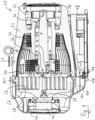
- the Fig. 1 shows a vacuum pump designed as a scroll pump 20.
- This comprises a first housing element 22 and a second housing element 24, the second housing element 24 having a pump-active structure, namely a spiral wall 26.
- the second housing element 24 thus forms a fixed spiral component of the scroll pump 20.
- the spiral wall 26 interacts with a spiral wall 28 of a movable spiral component 30, the movable spiral component 30 being eccentrically excited via an eccentric shaft 32 to generate a pumping effect.
- a gas to be pumped is conveyed from an inlet 31, which is defined in the first housing element 22, to an outlet 33, which is defined in the second housing element 24.
- the eccentric shaft 32 is driven by a motor 34 and supported by two roller bearings 36. It comprises an eccentric pin 38 arranged eccentrically to its axis of rotation, which transmits its eccentric deflection to the movable spiral component 30 via a further roller bearing 40.
- spiral component 30 is also Fig. 1 left-hand end of a bellows 42, the right-hand end of which is attached to the first housing element 22. The left-hand end of the bellows 42 follows the deflection of the movable spiral component 30.
- the scroll pump 20 comprises a fan 44 for generating a cooling air flow.
- An air guide hood 46 is provided for this cooling air flow, to which the fan 44 is also attached.
- the air guide hood 46 and the housing elements 22 and 24 are shaped in such a way that the cooling air flow essentially flows around the entire pump housing and thus achieves good cooling performance.
- the scroll pump 20 further comprises an electronics housing 48 in which a control device and power electronics components for driving the motor 34 are arranged.
- the electronics housing 48 also forms a base for the pump 20. Between the electronics housing 48 and the first housing element 22, a channel 50 is visible through which an air flow generated by the fan 44 is guided along the first housing element 22 and also along the electronics housing 48, so that both are effectively cooled.
- the electronics housing 48 is in Fig. 2 illustrated in more detail. It comprises several separate chambers 52. Electronic components can be encapsulated in these chambers 52 and are thus advantageously shielded. Preferably, the smallest possible amount of encapsulation material can be used when encapsulating the electronic components. For example, the encapsulation material can first be introduced into the chamber 52 and then the electronic component can be pressed in.
- the chambers 52 can be designed in such a way that different variants of the electronic components, in particular different assembly variants of a circuit board, can be arranged in the electronic housing 48 and/or encapsulated. For certain variants, individual chambers 52 can also remain empty, i.e. no electronic component In this way, a so-called modular system for different pump types can be implemented in a simple manner.
- the potting material can in particular be designed to be heat-conducting and/or electrically insulating.
- a plurality of walls or ribs 54 are formed on the rear side of the electronics housing 48, which define a plurality of channels 50 for conducting a cooling air flow.
- the chambers 52 also enable particularly good heat dissipation from the electronic components arranged in them, in particular in conjunction with a heat-conducting potting material, and towards the ribs 54. The electronic components can thus be cooled particularly effectively and their service life is improved.
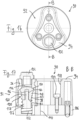
- FIG. 3 the scroll pump 20 is shown as a whole in perspective, but the air guide hood 46 is hidden so that the fixed spiral component 24 and the fan 44 are visible.
- the fixed spiral component 24 has a plurality of recesses 56 arranged in a star shape, each of which defines ribs 58 arranged between the recesses 56.
- the cooling air flow generated by the fan 44 leads through the recesses 56 and past the ribs 58 and thus cools the fixed spiral component 24 particularly effectively.
- the cooling air flow first flows around the fixed spiral component 24 and only then around the first housing element 22 or the electronics housing 48. This arrangement is particularly advantageous because the pump-active area of the pump 20 develops a lot of heat due to the compression during operation and is therefore primarily cooled here.
- the pump 20 comprises a pressure sensor 60 integrated therein. This is arranged inside the air guide hood 46 and screwed into the fixed spiral component 24.
- the pressure sensor 60 is connected to the electronics housing 48 and a control device arranged therein via a cable connection (only partially shown).
- the pressure sensor 60 is integrated into the control of the Scroll pump 20.
- the motor 34 which is in Fig. 1 visible, depending on a pressure measured by the pressure sensor 60.
- the high vacuum pump can only be switched on if the pressure sensor 60 measures a sufficiently low pressure. In this way, the high vacuum pump can be protected from damage.
- Fig. 4 shows the pressure sensor 60 and its arrangement on the fixed spiral component 24 in a cross-sectional view.
- a channel 62 is provided for the pressure sensor 60, which here opens into a non-pumping outdoor area between the spiral walls 26 and 28 of the fixed or movable spiral components 24 and 30.
- the pressure sensor thus measures a suction pressure of the pump.
- a pressure between the spiral walls 26 and 28 in a pumping active area can also be measured.
- intermediate pressures can also be measured, for example.
- the pressure sensor 60 allows, for example by determining compression, in particular to detect a state of wear of the pump-active components, in particular of a sealing element 64 also referred to as a tip seal.
- the measured intake pressure can also be used to regulate the pump (including pump speed).
- an intake pressure can be specified by software and an intake pressure can be set by varying the pump speed. It is also conceivable that, depending on the measured pressure, a pressure increase due to wear can be compensated by increasing the speed. In this way, a tip seal change can be postponed or longer change intervals can be implemented.
- the data from the pressure sensor 60 can therefore generally be used, for example, to determine wear, to control the pump in a given situation, to control the process, etc.
- the pressure sensor 60 can, for example, be provided optionally. Instead of the pressure sensor 60, for example, a blind plug can be provided to close the channel 62. A pressure sensor 60 can then, for example, be retrofitted if required. Particularly with regard to retrofitting, but also generally advantageous, it can be provided that the pressure sensor 60 is automatically recognized when connected to the control device of the pump 20.
- the pressure sensor 60 is arranged in the cooling air flow of the fan 44. This also advantageously cools it. This also means that no special measures need to be taken to increase the temperature resistance of the pressure sensor 60 and, consequently, a cost-effective sensor can be used.
- the pressure sensor 60 is arranged in particular such that the external dimensions of the pump 20 are not increased by it and the pump 20 consequently remains compact.
- the movable spiral component 30 is shown in different views.
- the spiral structure of the spiral wall 28 is particularly clearly visible.
- the spiral component 30 comprises a base plate 66 from which the spiral wall 28 extends.
- a side of the base plate 66 facing away from the spiral wall 28 is in Fig. 6 visible.
- the base plate includes, among other things, several mounting recesses, for example for mounting the bearing 40 and the bellows 42, which are in Fig. 1 are visible.
- retaining projections 68 are provided, spaced apart over the circumference of the base plate 66 and evenly distributed over the circumference.
- the retaining projections 68 extend radially outwards. In particular, the retaining projections 68 all have the same radial height.
- a first intermediate section 70 of the circumference of the base plate 66 extends between two of the holding projections 68.
- This first intermediate section 70 has a greater radial height than a second intermediate section 72 and than a third intermediate section 74.
- the first intermediate section 70 is arranged opposite an outermost 120° section of the spiral wall 28.
- the base plate 66 and the spiral wall 28 are preferably manufactured together from a solid material, i.e. the spiral wall 28 and the base plate 66 are formed as one piece.
- the spiral component 30 can be clamped directly to the holding projections 68.
- the Fig. 6 shown side of the base plate 66 are machined, in particular the fastening recesses are made.
- the spiral wall 28 can also be machined from the solid material within the scope of this clamping.
- the spiral component 30 can be clamped, for example, with a clamping device 76, as shown in Fig. 7
- a clamping device 76 has a hydraulic three-jaw chuck 78 for direct contact with the three retaining projections 68.
- the clamping device 76 has a continuous recess 80 through which a tool access to the spiral component 30, in particular to the Fig. 6 shown side thereof.
- machining operations can be carried out from both sides during clamping, in particular at least a finishing machining of the spiral wall 28 and an introduction of fastening recesses.
- the contour of the retaining projections 68 and the clamping pressure of the clamping device 76 are preferably selected so that no critical deformations of the spiral component 30 occur.
- the three retaining projections 68 are preferably selected so that the external dimension, i.e. the maximum diameter of the spiral component 30, is not increased. This means that material and machining volume can be saved.
- the retaining projections 68 are in particular designed and/or arranged at such an angular position that the screw connection of the corrugated bellows 42 is accessible.
- the number of screw connection points of the corrugated bellows 42 is preferably not equal to the number of retaining projections 68 on the movable spiral component 30.
- balancing weights 82 are attached to compensate for any imbalance of the excited system.
- the area of the Fig. 1 right-hand balance weight 82 is in Fig. 8 shown enlarged.
- the balancing weight 82 is screwed to the eccentric shaft 32.
- FIG. 9 A similar image section is in Fig. 9 for another scroll pump, preferably of the same series as pump 20 of the Fig. 1
- the Fig. 9 The underlying pump has different dimensions and therefore requires a different balancing weight 82.
- the eccentric shafts 32, the balancing weights 82 and the housing elements 22 are dimensioned such that only a specific type of the two types of balancing weights 82 shown can be mounted on the eccentric shaft 32 at the respective mounting position shown.
- the balance weights 82 are in the Fig. 8 and 9 together with certain dimensions of the installation space provided for it, in order to clarify that the balancing weight 82 of the Fig. 9 not on the eccentric shaft 32 can be mounted and vice versa. It is understood that the dimensions given are purely examples.
- the balancing weight 82 of the Fig. 8 is shorter in the corresponding direction, namely 9 mm long, so it can be installed without any problems.
- the balance weight 82 of the Fig. 9 has a longitudinal extension of 11 mm measured from the mounting hole.
- the balancing weight 82 of the Fig. 9 not on the eccentric shaft 32 of the Fig. 8 cannot be mounted because the shaft shoulder 86 collides with the balance weight 82 during an attempted assembly or because the balance weight 82 of the Fig. 9 not fully in contact with the eccentric shaft 82 of the Fig. 8 Because the balance weight 82 of the Fig.
- Fig. 9 The distance in the longitudinal direction between the mounting hole 84 and a housing shoulder 88 is 17.5 mm.
- the balancing weight 82 of the Fig. 8 With its extension of 21.3 mm, when inserting the eccentric shaft 32, the Fig. 9 collide with the housing shoulder 88, so that complete assembly would not be possible. Incorrect assembly is possible at first, but is reliably detected. If the balancing weight 82 of the Fig. 8 on the eccentric shaft 32 of the Fig. 9 the extension of 21.3 mm would collide with the shaft shoulder 86, which is arranged only at a distance of 13.7 mm from the mounting hole 84.
- the balancing weights 82 in particular a motor-side balancing weight 82, are generally designed in such a way that confusion of the balancing weight with those of other sizes is avoided during assembly and/or servicing.
- the balancing weights are preferably fastened using through-bolts. Similar balancing weights of different pump sizes are in particular designed in such a way that installation of the wrong balancing weight is prevented due to adjacent steps on the shaft, the positions of the thread and through-hole of the balancing weight and steps within the housing.
- FIG. 10 and 11 A gas ballast valve 90 of the scroll pump 20 is shown. This is also shown in the overall view of the pump 20 in Fig. 3 visible and arranged on the fixed spiral component 24.
- the gas ballast valve 90 comprises an actuating handle 92. This comprises a plastic body 94 and a base element 96, which is preferably made of stainless steel.
- the base element 96 comprises a through-hole 98, which is provided on the one hand for connecting and introducing a ballast gas and on the other hand comprises a check valve 100.
- the hole 98 is also closed in the illustrations by means of a plug 102.
- a filter can also be provided, for example, wherein the ballast gas can preferably be air and enters the valve 90 directly via the filter.
- the operating handle 92 is attached to a rotatable element 106 of the valve 90 by means of three fastening screws 104, which are arranged in a respective bore 108 and of which in the selected sectional view of the Fig. 11 only one is visible.
- the rotatable element 106 is rotatably attached to the second housing element 24 by means of a fastening screw (not shown) which runs through a bore 110.
- a torque applied manually to the operating handle 92 is transmitted to the rotatable element 106, thus rotating it.
- the bore 98 thus comes into communication with the interior of the housing.
- Three switching positions are provided for the valve 90, namely the Fig. 10 shown, which is a locked position, and a position rotated to the right and to the left, in which the bore 98 is in communication with different areas of the interior of the housing.
- the holes 108 and 110 are closed by a cover 112.
- the sealing effect of the gas ballast valve 90 is based on axially pressed O-rings. When the valve 90 is actuated, a relative movement is exerted on the O-rings. If contaminants, such as particles, get onto the surface of an O-ring, this poses the risk of premature failure.
- the cover 112 prevents contaminants and the like from penetrating the screws of the handle 92.
- This cover 112 is attached via an interference fit of three centering elements. Specifically, the cover 112 has a plug-in pin (not shown) for each hole 108, with which the cover 112 is held in the holes 108.
- the holes 108 and 110 and the fastening screws arranged therein are thus protected from contamination.
- the fastening screw (not shown) arranged in the hole 110 which allows a rotary movement, the ingress of contamination into the valve mechanism can be effectively minimized and the service life of the valve can thus be improved.
- the plastic handle with overmolded stainless steel base ensures good corrosion resistance and low manufacturing costs. Furthermore, the The plastic of the handle is cooler due to the limited heat conduction and is therefore easier to use.
- a speed control is preferably provided.
- the fan is controlled by means of PWM depending on the power consumption and temperature of the power module, which is housed in the electronics housing 48, for example.
- the speed is set in line with the power consumption. However, control is only permitted when the module temperature is above 50 °C. If the pump enters temperature ranges of possible derating (temperature-related power reduction), the max. fan speed is automatically controlled. This control makes it possible to achieve a minimum noise level when the pump is cold, to ensure a low noise level at final pressure or at low load - corresponding to the pump noise, to achieve optimal cooling of the pump with a low noise level at the same time, and to ensure the max. cooling capacity before a temperature-related power reduction.
- the maximum fan speed can be adjusted, especially depending on the situation. For example, if a system has a high tolerance to water vapor, it may be useful to reduce the maximum fan speed.
- FIG. 12 the movable spiral component 30 is partially and opposite Fig. 5 enlarged.
- a sectional view of the spiral component 30 along the Fig. 12 indicated line A:A is in Fig. 13 shown schematically and not to scale.
- the spiral wall 28 has, at its end facing away from the base plate 66 and facing a base plate of the fixed spiral component 24 (not shown here), a groove 114 for inserting a sealing element (also not shown here). 64, namely a so-called tip seal.
- the arrangement in the operating state is shown in Fig. 4 clearly visible.
- the groove 114 is delimited to the outside and to the inside by two opposite side walls, namely by an inner side wall 116 and an outer side wall 118.
- the outer side wall 118 is thicker than the inner side wall 116 in the first spiral section 120 and thicker than both side walls 116 and 118 in another, second spiral section 122.
- the first spiral section 120 extends from Fig. 12 indicated place to the outer end of the spiral wall 28, as is also the case in Fig. 5 is indicated.
- the first spiral section 120 extends here, for example, over approximately 163°.
- the first spiral section 120 forms an outer end section of the spiral wall 28.
- the first spiral section 120 is arranged at least partially, in particular completely, in a non-pumping area of the spiral wall 28.
- the first spiral section 120 can at least substantially completely fill the non-pumping area of the spiral wall 28.
- the first intermediate section 70 between two retaining projections 68 which has a greater radial height than other intermediate sections 72 and 74, can preferably be arranged opposite the first spiral section 120.
- An imbalance introduced by the thicker side wall 118 can thus be compensated by the greater weight of the first intermediate section 70.
- the movable spiral component should generally preferably have a low dead weight.
- the spiral walls are therefore generally very thin. Furthermore, thinner walls result in smaller pump dimensions (significant outer diameter).
- the side walls of the tip seal groove are therefore particularly thin.
- the ratio of the tip seal wall thickness to the total spiral wall thickness is, for example, a maximum of 0.17.
- the spiral wall tip is very sensitive to impacts during handling, such as during assembly or when changing the tip seal. Light impacts, e.g. during transport, can push the side wall of the groove inwards so that the tip seal can no longer be installed.
- the groove has an asymmetrical wall thickness, in particular a local thickening of the spiral wall towards the outside. This area is preferably not pump-active and can therefore be manufactured with a larger tolerance.
- the one-sided thickening on the, particularly the last half turn significantly reduces damage. At other parts of the component, thickening of the spiral wall is preferably not necessary, since the wall is protected by protruding elements of the component.
- the in Fig. 1 The air guide hood 46 shown defines an air flow, as indicated by a dashed arrow 124.
- the fan 44 is connected to a control device in the electronics housing 48 via a cable (not shown) which runs through the air guide hood 46, and via a plug connection.
- This comprises a socket 126 and a plug 128.
- the socket 126 is mounted on the electronics housing 48 and/or attached to a circuit board arranged in the electronics housing 48.
- the socket 126 is also provided, for example, in the Fig. 2 and 3 visible.
- the connector 128 is connected to the fan 44 via the cable not shown.
- the plug connection 126, 128 is separated from the air flow 124 by a partition 130.
- the air flow 124 which may contain dust or similar contaminants, is thus kept away from the plug connection 126, 128.
- the plug connection 126, 128 itself is protected and, on the other hand, it prevents dirt from entering the electronics housing 48 through the opening provided for the socket 126 and reaching the control device and/or power electronics.
- the air guide hood 46 is in Fig. 14 shown separately and in perspective. Among other things, the partition wall 130 with the space defined behind it for the connector 128 is visible.
- the partition wall 130 comprises a recess 132, designed here as a V-shaped notch, for passing a cable from the connector 128 to the fan 44.
- the partition 130 ensures that the air drawn in does not reach the electronics via the opening in the connector 126, 128.
- the cable of the fan is guided laterally through the partition 130 through the V-shaped notch 132.
- the notch 132 has a lateral offset to the connector 126, 128, which creates a labyrinth effect and thus further reduces the leakage of cooling air to the connector 126, 128.
- a partition 130 within the air guide hood 46 also improves the air flow into the channel 50 between the electronics housing 48 and the pump housing 22. There is less turbulence and back pressure for the fan 44.
- the Fig. 15 shows a contact area between the first housing element 22 and the second housing element or fixed spiral component 24 in a schematic sectional view.
- the second housing element 24 is partially inserted into the first housing element 22 with a transition fit 134.
- a seal is provided by means of an O-ring 136.
- the transition fit 134 also serves, for example, to center the second housing element 24 relative to the first housing element 22.
- a forcing thread 138 is provided.
- a second forcing thread can also be provided at least substantially radially opposite.
- the fastening screws 142 provided for fastening the second housing element 24 to the first housing element 22 can be used for pressing, as shown for example in the Fig. 1 and 3
- the forcing thread 138 preferably has the same type of thread as the fastening thread provided for the fastening screws 142.
- a countersink 140 is provided on the second housing element 22, which is associated with the forcing thread 138. If abrasion particles are discharged when the screw is screwed into the forcing thread 138, they collect in the countersink 140. This prevents such abrasion particles from, for example, preventing the housing elements 22 and 24 from completely engaging one another.
- the air guide hood 46 has at least one, in particular additional, Fig. 14 shown dome 144, which only allows the air guide hood 46 to be mounted when the screws used for forcing, in particular the fastening screws 142, have been removed again.
- the air guide hood 46 with the dome 144 is designed in such a way that it would collide with a screw head of a forcing screw that might be screwed into the forcing thread 138, so that the air guide hood 46 could not be fully mounted.
- the air guide hood 46 can only be mounted when the forcing screws are completely removed.
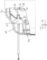
- the Fig. 16 and 17 show a gas ballast valve 90, which is similar to that of the Fig. 10 and 11 and can preferably be arranged on a scroll pump, e.g. the scroll pump 20.
- the reference numerals are assigned accordingly and reference is made to the above explanations.
- the gas ballast valve 90 is shown without a cover 112 as described above. It is understood that such a cover can also be used here.
- the check valve 100 has a passage 146 for a fluid, here for the ballast gas. This is releasably closed with a plug 102.
- the check valve 100 comprises a movable closing element 148 and a sealing seat 150.
- the movable closing element 148 and the sealing seat 150 are designed to correspond in such a way that the closing element 148 blocks the passage 146 when it is - as in Fig. 17 shown - is in contact with the sealing seat 150.
- the contact surfaces of the closing element 148 and the sealing seat 150 are spherical.
- the closing element 148 is pre-tensioned against the sealing seat 150 by means of a spring 152.
- the spring 152 is designed here as a helical compression spring. It is supported on the one hand on the rotatable element 106 and on the other hand rests against the closing element 148.
- the closing element 148 extends with a spring mandrel section 154 into an inner region of the spring 152. This serves in particular to precisely guide the closing element 148 in relation to the spring 152.
- the mass element 152 is arranged at least partially in the inner region of the spring 152, which enables a compact construction.
- the check valve 100 further comprises a mass element 156, which is firmly connected to the closing element 148. While the closing element 148 is made of plastic here, for example, the mass element 156 is made of metal, preferably steel, for example.
- the mass element 156 thus gives the movable assembly consisting of the closing element 148 and the mass element 156 a significantly greater mass than the closing element 148 would have on its own. This assembly therefore has a high inertia, which, as described above, leads to a reduction in noise emissions during operation of the gas ballast valve 90 in a vacuum device, in particular a vacuum pump, preferably a scroll pump.
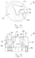
- the mass element 156 comprises a mass section 158, which is designed to be as large as possible in order to achieve a high mass.
- the mass element 156 comprises a connecting section 160, which is designed to establish a connection to the closing element 148.
- the mass section 158 and the connecting section 160 are separated from one another by a shoulder 162.
- connection between the mass element 156 and the closing element 148 is designed in such a way that the connecting section 160 of the mass element 156 is inserted into a recess 164 of the closing element 148.
- the connecting section 160 has several elevations 166 which act as barbs.
- the elevations 166 will be discussed below with reference to the Fig. 18 to 20 discussed in more detail below.
- the connecting section 160 could also have a thread and be screwed into the closing element 148.
- the mass element 156 is arranged on a side of the closing element 148 which faces away from the contact surface of the closing element 148 for contact with the sealing seat 150.
- the mass element 156 could also be arranged starting from the closing element 148 in Fig. 17 extend upwards, whereby the connecting means would have to be adapted accordingly.
- the mass element 156 can therefore, for example, be in a locking direction, which Fig. 17 from bottom to top, in front of the closing element 148, as shown in Fig. 17 is the case, and/or also in the locking direction behind the locking element 148.
- the mass element 156 could also be completely integrated into the locking element 148.
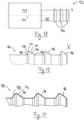
- Fig. 18 1 shows an exemplary embodiment of a mass element 156 in more detail.
- the mass element 156 comprises a mass section 158 and a connecting section 160.
- the mass section 158 and the connecting section 160 are essentially cylindrical.
- the mass element 156 can be, for example, a turned part, ie a component produced by turning.
- the connecting section 160 is equipped with circumferential elevations 166 which, when connected to a closing element 148, form barbs and hold the connecting section 160 in a corresponding recess 164 of the closing element 148.
- the recess 164 can, for example, have preformed circumferential recesses corresponding to the elevations 166.
- the elevations 166 can partially elastically deform the material of the closing element 148 when the connecting section 160 is inserted into the recess 164 and then hold it in the recess 164 by elastic forces, the shape of the elevations 166 forming an obstacle to removing the connecting section 160 from the recess 164.
- Fig. 18 In the embodiment shown, three elevations 166 are provided. This number has proven to be particularly advantageous with regard to the strength of the connection. However, more or fewer elevations can also be provided, for example.
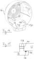
- FIG. 18 A sub-area X is marked, which in Fig. 19 is shown enlarged.
- the shape of the elevations 166 is clearly visible here.
- the three elevations 166 are essentially identical, which is why the shape can only be determined based on the Fig. 19 left elevation 166 is illustrated in more detail.
- the elevation 166 comprises a curve 168, an annular surface 170, which is perpendicular to the Fig. 18 indicated cylinder axis 172, a curve 174, a conical section 176 and a further curve 178.
- the curves can in principle be omitted.
- a connecting section 160 is shown in a representation similar to that of the Fig. 19
- three elevations 166 are planned, which those of Fig. 19
- the difference to be emphasized here is that instead of a surface 170 perpendicular to the cylinder axis 172, a further conical section 180 is provided. This is conical in the opposite direction to the conical section 176.
Landscapes
- Engineering & Computer Science (AREA)
- General Engineering & Computer Science (AREA)
- Mechanical Engineering (AREA)
- Applications Or Details Of Rotary Compressors (AREA)
- Check Valves (AREA)
- Rotary Pumps (AREA)
Priority Applications (1)
| Application Number | Priority Date | Filing Date | Title |
|---|---|---|---|
| EP24216474.7A EP4491877B1 (fr) | 2020-07-22 | 2020-07-22 | Pompe à vide avec clapet anti-retour |
Applications Claiming Priority (2)
| Application Number | Priority Date | Filing Date | Title |
|---|---|---|---|
| EP20187213.2A EP3708840B1 (fr) | 2020-07-22 | 2020-07-22 | Pompe à vide avec clapet antiretour |
| EP24216474.7A EP4491877B1 (fr) | 2020-07-22 | 2020-07-22 | Pompe à vide avec clapet anti-retour |
Related Parent Applications (2)
| Application Number | Title | Priority Date | Filing Date |
|---|---|---|---|
| EP20187213.2A Division EP3708840B1 (fr) | 2020-07-22 | 2020-07-22 | Pompe à vide avec clapet antiretour |
| EP20187213.2A Division-Into EP3708840B1 (fr) | 2020-07-22 | 2020-07-22 | Pompe à vide avec clapet antiretour |
Publications (3)
| Publication Number | Publication Date |
|---|---|
| EP4491877A2 true EP4491877A2 (fr) | 2025-01-15 |
| EP4491877A3 EP4491877A3 (fr) | 2025-04-02 |
| EP4491877B1 EP4491877B1 (fr) | 2026-04-22 |
Family
ID=71741704
Family Applications (2)
| Application Number | Title | Priority Date | Filing Date |
|---|---|---|---|
| EP24216474.7A Active EP4491877B1 (fr) | 2020-07-22 | 2020-07-22 | Pompe à vide avec clapet anti-retour |
| EP20187213.2A Active EP3708840B1 (fr) | 2020-07-22 | 2020-07-22 | Pompe à vide avec clapet antiretour |
Family Applications After (1)
| Application Number | Title | Priority Date | Filing Date |
|---|---|---|---|
| EP20187213.2A Active EP3708840B1 (fr) | 2020-07-22 | 2020-07-22 | Pompe à vide avec clapet antiretour |
Country Status (1)
| Country | Link |
|---|---|
| EP (2) | EP4491877B1 (fr) |
Families Citing this family (2)
| Publication number | Priority date | Publication date | Assignee | Title |
|---|---|---|---|---|
| DE102021000929A1 (de) * | 2021-02-22 | 2022-08-25 | KSB SE & Co. KGaA | Heizungsumwälzpumpe mit spritzwassergeschütztem elektrischen Anschluss |
| EP4506537B1 (fr) * | 2023-08-08 | 2025-10-08 | Pfeiffer Vacuum Technology AG | Pompe à vide à spirales |
Family Cites Families (5)
| Publication number | Priority date | Publication date | Assignee | Title |
|---|---|---|---|---|
| BR8802893A (pt) * | 1988-06-09 | 1990-01-23 | Brasil Compressores Sa | Sistema de descarga para compressor hermetico |
| JP3564769B2 (ja) * | 1995-01-23 | 2004-09-15 | 松下電器産業株式会社 | スクロール圧縮機 |
| DE10046768B4 (de) * | 2000-09-21 | 2011-08-11 | Leybold Vakuum GmbH, 50968 | Schraubenvakuumpumpe mit Bypass-Ventil |
| JP7220692B2 (ja) * | 2019-10-07 | 2023-02-10 | プファイファー・ヴァキューム・ゲーエムベーハー | 真空ポンプ、スクロールポンプ及びその製造方法 |
| EP3754200B1 (fr) * | 2019-10-07 | 2021-12-08 | Pfeiffer Vacuum Gmbh | Pompe à vide à spirales et procédé de montage |
-
2020
- 2020-07-22 EP EP24216474.7A patent/EP4491877B1/fr active Active
- 2020-07-22 EP EP20187213.2A patent/EP3708840B1/fr active Active
Also Published As
| Publication number | Publication date |
|---|---|
| EP4491877A3 (fr) | 2025-04-02 |
| EP3708840A2 (fr) | 2020-09-16 |
| EP3708840A3 (fr) | 2021-03-10 |
| EP4491877B1 (fr) | 2026-04-22 |
| EP3708840B1 (fr) | 2025-02-26 |
Similar Documents
| Publication | Publication Date | Title |
|---|---|---|
| EP4095387B1 (fr) | Pompe à vide à spirales avec capteur de pression intégré | |
| EP3754200B1 (fr) | Pompe à vide à spirales et procédé de montage | |
| DE2639174C2 (fr) | ||
| DE4227332C2 (de) | Schraubenverdichter | |
| DE69520246T2 (de) | Schraubenkolbenmaschine | |
| EP3617511B1 (fr) | Pompes à spirales et procédé de fabrication pour des telles pompes | |
| EP1979618B1 (fr) | Groupe de compresseurs à vis à plusieurs étages | |
| EP0699826A1 (fr) | Circuit de liquide avec un filtre au courant principal | |
| DE60220247T2 (de) | Horizontaler spiralverdichter | |
| EP3708840B1 (fr) | Pompe à vide avec clapet antiretour | |
| DE4326408A1 (de) | Vielfach-Axialkolbenverdichter | |
| DE3124247C1 (de) | Schraubenverdichter | |
| DE60218720T2 (de) | Zusammensetzung eines schraubenkompressors und methode | |
| DE102017102645B4 (de) | Kältemittel-Scrollverdichter für die Verwendung innerhalb einer Wärmepumpe | |
| DE3118297C2 (de) | Zahnradpumpe | |
| WO2019063315A1 (fr) | Trousse comportant un actionneur d'arbre à cames | |
| DE4425406A1 (de) | Abstützkonstruktion für eine Drehwelle eines Kompressors | |
| DE69706116T2 (de) | Flügelzellenverdichter | |
| DE2911655A1 (de) | Rollkolbenpumpe | |
| DE4135221C2 (de) | Flügelzellenpumpe | |
| DE102004003137A1 (de) | Kompressionsvorrichtung für gasförmige Medien | |
| DE112007002363T5 (de) | Pneumatischer Flügelzellenmotor | |
| DE10316651B4 (de) | Taumelscheibenkompressor für eine Fahrzeug-Klimaanlage mit Spalt zwischen Gehäuse und Zylinderblock | |
| WO2026052676A1 (fr) | Compresseur à piston radial | |
| DE102023102154A1 (de) | Kühlmittelpumpe mit vorgeformten Leckagereservoir und Verfahren zur Herstellung eines Leckagereservoirs |
Legal Events
| Date | Code | Title | Description |
|---|---|---|---|
| PUAI | Public reference made under article 153(3) epc to a published international application that has entered the european phase |
Free format text: ORIGINAL CODE: 0009012 |
|
| STAA | Information on the status of an ep patent application or granted ep patent |
Free format text: STATUS: THE APPLICATION HAS BEEN PUBLISHED |
|
| AC | Divisional application: reference to earlier application |
Ref document number: 3708840 Country of ref document: EP Kind code of ref document: P |
|
| AK | Designated contracting states |
Kind code of ref document: A2 Designated state(s): AL AT BE BG CH CY CZ DE DK EE ES FI FR GB GR HR HU IE IS IT LI LT LU LV MC MK MT NL NO PL PT RO RS SE SI SK SM TR |
|
| REG | Reference to a national code |
Ref legal event code: R079 Free format text: PREVIOUS MAIN CLASS: F04C0029000000 Ref country code: DE Ref document number: 502020013048 Country of ref document: DE Ipc: F04C0029120000 |
|
| PUAL | Search report despatched |
Free format text: ORIGINAL CODE: 0009013 |
|
| AK | Designated contracting states |
Kind code of ref document: A3 Designated state(s): AL AT BE BG CH CY CZ DE DK EE ES FI FR GB GR HR HU IE IS IT LI LT LU LV MC MK MT NL NO PL PT RO RS SE SI SK SM TR |
|
| RIC1 | Information provided on ipc code assigned before grant |
Ipc: F04C 29/00 20060101ALI20250224BHEP Ipc: F04C 29/06 20060101ALI20250224BHEP Ipc: F04C 25/02 20060101ALI20250224BHEP Ipc: F04C 18/02 20060101ALI20250224BHEP Ipc: F16K 1/54 20060101ALI20250224BHEP Ipc: F04C 29/12 20060101AFI20250224BHEP |
|
| STAA | Information on the status of an ep patent application or granted ep patent |
Free format text: STATUS: REQUEST FOR EXAMINATION WAS MADE |
|
| 17P | Request for examination filed |
Effective date: 20251001 |
|
| GRAP | Despatch of communication of intention to grant a patent |
Free format text: ORIGINAL CODE: EPIDOSNIGR1 |
|
| STAA | Information on the status of an ep patent application or granted ep patent |
Free format text: STATUS: GRANT OF PATENT IS INTENDED |
|
| INTG | Intention to grant announced |
Effective date: 20251124 |
|
| GRAJ | Information related to disapproval of communication of intention to grant by the applicant or resumption of examination proceedings by the epo deleted |
Free format text: ORIGINAL CODE: EPIDOSDIGR1 |
|
| STAA | Information on the status of an ep patent application or granted ep patent |
Free format text: STATUS: REQUEST FOR EXAMINATION WAS MADE |
|
| GRAP | Despatch of communication of intention to grant a patent |
Free format text: ORIGINAL CODE: EPIDOSNIGR1 |
|
| STAA | Information on the status of an ep patent application or granted ep patent |
Free format text: STATUS: GRANT OF PATENT IS INTENDED |
|
| INTC | Intention to grant announced (deleted) | ||
| INTG | Intention to grant announced |
Effective date: 20260128 |
|
| GRAS | Grant fee paid |
Free format text: ORIGINAL CODE: EPIDOSNIGR3 |
|
| GRAA | (expected) grant |
Free format text: ORIGINAL CODE: 0009210 |
|
| STAA | Information on the status of an ep patent application or granted ep patent |
Free format text: STATUS: THE PATENT HAS BEEN GRANTED |
|
| AC | Divisional application: reference to earlier application |
Ref document number: 3708840 Country of ref document: EP Kind code of ref document: P |
|
| AK | Designated contracting states |
Kind code of ref document: B1 Designated state(s): AL AT BE BG CH CY CZ DE DK EE ES FI FR GB GR HR HU IE IS IT LI LT LU LV MC MK MT NL NO PL PT RO RS SE SI SK SM TR |
|
| REG | Reference to a national code |
Ref country code: CH Ref legal event code: F10 Free format text: ST27 STATUS EVENT CODE: U-0-0-F10-F00 (AS PROVIDED BY THE NATIONAL OFFICE) Effective date: 20260422 Ref country code: GB Ref legal event code: FG4D Free format text: NOT ENGLISH |