EP4492013A1 - Dispositif de détection - Google Patents
Dispositif de détection Download PDFInfo
- Publication number
- EP4492013A1 EP4492013A1 EP24172641.3A EP24172641A EP4492013A1 EP 4492013 A1 EP4492013 A1 EP 4492013A1 EP 24172641 A EP24172641 A EP 24172641A EP 4492013 A1 EP4492013 A1 EP 4492013A1
- Authority
- EP
- European Patent Office
- Prior art keywords
- code
- track
- individual
- word
- absolute
- Prior art date
- Legal status (The legal status is an assumption and is not a legal conclusion. Google has not performed a legal analysis and makes no representation as to the accuracy of the status listed.)
- Granted
Links
Images


Classifications
-
- G—PHYSICS
- G01—MEASURING; TESTING
- G01D—MEASURING NOT SPECIALLY ADAPTED FOR A SPECIFIC VARIABLE; ARRANGEMENTS FOR MEASURING TWO OR MORE VARIABLES NOT COVERED IN A SINGLE OTHER SUBCLASS; TARIFF METERING APPARATUS; MEASURING OR TESTING NOT OTHERWISE PROVIDED FOR
- G01D5/00—Mechanical means for transferring the output of a sensing member; Means for converting the output of a sensing member to another variable where the form or nature of the sensing member does not constrain the means for converting; Transducers not specially adapted for a specific variable
- G01D5/12—Mechanical means for transferring the output of a sensing member; Means for converting the output of a sensing member to another variable where the form or nature of the sensing member does not constrain the means for converting; Transducers not specially adapted for a specific variable using electric or magnetic means
- G01D5/244—Mechanical means for transferring the output of a sensing member; Means for converting the output of a sensing member to another variable where the form or nature of the sensing member does not constrain the means for converting; Transducers not specially adapted for a specific variable using electric or magnetic means influencing characteristics of pulses or pulse trains; generating pulses or pulse trains
- G01D5/245—Mechanical means for transferring the output of a sensing member; Means for converting the output of a sensing member to another variable where the form or nature of the sensing member does not constrain the means for converting; Transducers not specially adapted for a specific variable using electric or magnetic means influencing characteristics of pulses or pulse trains; generating pulses or pulse trains using a variable number of pulses in a train
- G01D5/2451—Incremental encoders
- G01D5/2452—Incremental encoders incorporating two or more tracks having an (n, n+1, ...) relationship
-
- G—PHYSICS
- G01—MEASURING; TESTING
- G01D—MEASURING NOT SPECIALLY ADAPTED FOR A SPECIFIC VARIABLE; ARRANGEMENTS FOR MEASURING TWO OR MORE VARIABLES NOT COVERED IN A SINGLE OTHER SUBCLASS; TARIFF METERING APPARATUS; MEASURING OR TESTING NOT OTHERWISE PROVIDED FOR
- G01D5/00—Mechanical means for transferring the output of a sensing member; Means for converting the output of a sensing member to another variable where the form or nature of the sensing member does not constrain the means for converting; Transducers not specially adapted for a specific variable
- G01D5/12—Mechanical means for transferring the output of a sensing member; Means for converting the output of a sensing member to another variable where the form or nature of the sensing member does not constrain the means for converting; Transducers not specially adapted for a specific variable using electric or magnetic means
- G01D5/244—Mechanical means for transferring the output of a sensing member; Means for converting the output of a sensing member to another variable where the form or nature of the sensing member does not constrain the means for converting; Transducers not specially adapted for a specific variable using electric or magnetic means influencing characteristics of pulses or pulse trains; generating pulses or pulse trains
- G01D5/249—Mechanical means for transferring the output of a sensing member; Means for converting the output of a sensing member to another variable where the form or nature of the sensing member does not constrain the means for converting; Transducers not specially adapted for a specific variable using electric or magnetic means influencing characteristics of pulses or pulse trains; generating pulses or pulse trains using pulse code
- G01D5/2497—Absolute encoders
-
- G—PHYSICS
- G01—MEASURING; TESTING
- G01D—MEASURING NOT SPECIALLY ADAPTED FOR A SPECIFIC VARIABLE; ARRANGEMENTS FOR MEASURING TWO OR MORE VARIABLES NOT COVERED IN A SINGLE OTHER SUBCLASS; TARIFF METERING APPARATUS; MEASURING OR TESTING NOT OTHERWISE PROVIDED FOR
- G01D5/00—Mechanical means for transferring the output of a sensing member; Means for converting the output of a sensing member to another variable where the form or nature of the sensing member does not constrain the means for converting; Transducers not specially adapted for a specific variable
- G01D5/26—Mechanical means for transferring the output of a sensing member; Means for converting the output of a sensing member to another variable where the form or nature of the sensing member does not constrain the means for converting; Transducers not specially adapted for a specific variable characterised by optical transfer means, i.e. using infrared, visible, or ultraviolet light
- G01D5/32—Mechanical means for transferring the output of a sensing member; Means for converting the output of a sensing member to another variable where the form or nature of the sensing member does not constrain the means for converting; Transducers not specially adapted for a specific variable characterised by optical transfer means, i.e. using infrared, visible, or ultraviolet light with attenuation or whole or partial obturation of beams of light
- G01D5/34—Mechanical means for transferring the output of a sensing member; Means for converting the output of a sensing member to another variable where the form or nature of the sensing member does not constrain the means for converting; Transducers not specially adapted for a specific variable characterised by optical transfer means, i.e. using infrared, visible, or ultraviolet light with attenuation or whole or partial obturation of beams of light the beams of light being detected by photocells
- G01D5/347—Mechanical means for transferring the output of a sensing member; Means for converting the output of a sensing member to another variable where the form or nature of the sensing member does not constrain the means for converting; Transducers not specially adapted for a specific variable characterised by optical transfer means, i.e. using infrared, visible, or ultraviolet light with attenuation or whole or partial obturation of beams of light the beams of light being detected by photocells using displacement encoding scales
- G01D5/34776—Absolute encoders with analogue or digital scales
- G01D5/34792—Absolute encoders with analogue or digital scales with only digital scales or both digital and incremental scales
- G01D5/34794—Optical encoders using the Vernier principle, i.e. incorporating two or more tracks having a (n, n+1, ...) relationship
Definitions
- the invention relates to a sensor device for determining an absolute position of a first object relative to a second object, which has a measuring embodiment arranged on the first object, a scanning device connected to the second object for scanning the measuring embodiment and an evaluation unit connected to the scanning device, wherein the measuring embodiment has an absolute code with a predetermined total resolution and the evaluation unit is designed to determine the absolute position by reading out a code word of the absolute code from signals received by the scanning device.
- Such encoder devices are used in a variety of ways to measure position, with a distinction being made in particular between linear and rotary systems.
- a linear encoder determines a displacement along an axis
- a rotary encoder or angle sensor is used to detect an angle of rotation or an angular position, for example the angular position of a motor shaft.
- position is therefore also understood to include angular positions.
- motor feedback systems in which a rotary encoder in a servo motor reports the actual speed of the motor shaft back to the control system.
- the measuring embodiment can have a structure of transparent and non-transparent areas and the scanning device can comprise a light-sensitive sensor arrangement.
- the code elements form a code track or measuring track.
- Magnetic encoder devices for example, detect with a Hall sensor corresponding magnetic structures of the measuring embodiment.
- An absolute code allows the determination of a unique position.
- the measuring embodiment comprises at least a first code track and a second code track, preferably running parallel to the first, and that the scanning device is designed to scan the code tracks together, wherein the code tracks have respective individual codes with predetermined individual code resolutions and the sum of the individual code resolutions is equal to the predetermined total resolution of the absolute code, wherein the first code track and the second code track comprise respective sequences of several identical code track segments, wherein the code track segments of the first code track are longer or shorter than the code track segments of the second code track and wherein the evaluation unit is designed to combine a code word of the first individual code with a code word of the second individual code in order to determine the code word of the absolute code.
- the two code tracks are offset from each other according to the Vernier principle, which ensures that the position is determined unambiguously.
- the length of the absolute code can be easily adjusted by omitting and/or adding code track segments while maintaining the resolution.
- the number of code elements per code word and the length of the individual code elements, i.e. the increment length, do not have to be changed for this, but can remain the same. This means that there is no need to provide an additional scanning device with an adapted detector geometry. This means that the same type of scanning device can be used for a variety of measuring lengths or measuring diameters.
- the evaluation unit can comprise an electronic circuit and can be connected to the scanning device wirelessly or by cable. Depending on the application, the scanning device and the evaluation unit can be integrated or designed as separate units.
- the resolution of a code is the number of code elements per code word, i.e. the number of bits per code word in a binary code.
- One embodiment of the invention provides that the individual code of the first code track has a zero word and the individual code of the second code track has no zero word, or that the individual code of the first code track has a one word and the individual code of the second code track has no one word.
- the zero word is the code word that is composed exclusively of code elements with the value zero.
- the one word is the code word that is composed exclusively of code elements with the value one.
- the individual code of the second code track in each code track segment is, for example, one bit shorter than the individual code of the first code track. This results in a continuous relative shift of the two individual codes to each other over the course of the codes, i.e. after each segment the codes shift by one bit relative to each other, which corresponds to the vernier principle. If, for example, two bits of the two individual codes are detected in parallel, this results in a sequence of 2+2 bits, which is unique over the course of the two individual codes.
- sequences of several identical code track segments have different track lengths and that a global zero word or a global one word is added to or inserted into the shorter sequence to compensate for the difference.
- the difference in the track lengths is therefore preferably filled with zeros or ones so that the code tracks are the same length overall.
- the maximum code length is not achieved because, for example, one bit is always missing per segment and ultimately a complete segment of the individual code of the first code track would have to be omitted in order to maintain uniqueness.
- This problem can be solved by assigning a global zero word to the individual code of the second code track. This means that in any segment, the number of bits with the value 0 that is missing across all segments is added at the position of the zero word. For an absolute code with two 2-bit sets, this means that if the second code is repeated four times, four individual bits with the value 0 are missing and must be added accordingly in order to achieve the maximum code length again.
- a segment length of the individual code of the first code track is therefore supplemented by several zero words of the individual code of the second code track, which makes the combination of the two individual codes unique again. In principle, it does not matter which codes are combined and what their relative displacement is to one another.
- the global zero word can in principle be inserted at any position in the relevant code track. However, it is preferred that the insertion takes place at the position with the most consecutive zeros in order to preserve the code.
- the number of identical code track segments of the first code track and/or the second code track is selected depending on a length of an area of the first object that can be used for scanning. Due to the design according to the invention, the absolute code can be scaled segment by segment while maintaining the resolution, so that the area to be measured can be covered particularly favorably.
- the resolution of the individual code of the first code track differs by a maximum of three and preferably by a maximum of one from the resolution of the individual code of the second code track.
- a division of the resolution at least approximately in half results in particularly favorable scalability.
- a different division is also possible, for example the combination of a code with a relatively high resolution with a code with a relatively low resolution, as long as the sum of the individual code resolutions is equal to the total resolution.
- the number of identical code track segments of the first code track can be equal to the number of identical code track segments of the second code track.
- first code track and the second code track are of equal length and/or comprise the same number of code elements and/or that the first code track and the second code track have code elements that have an equal length in the track direction. This enables a particularly simple design of the measuring embodiment and the scanning device.
- the evaluation unit can be designed to generate the code word of the absolute code by concatenating a code word of the first individual code with a code word of the second individual code, in particular one read out at the same time.
- the code word of the absolute code can be formed particularly quickly and easily by concatenation.
- the individual codes can be pseudorandom codes, which are preferably based on linear feedback shift registers.
- pseudorandom codes or pseudo-random codes code words are detected serially, the length of which preferably corresponds to the number of bits of the binary resolution of the code.
- the number of detectors in the scanning device preferably corresponds to at least the number of bits of the binary resolution.
- Each code word overlaps with its neighbors in both directions except for one bit, i.e. has all bits in common with them except for one, so that if the measuring embodiment is shifted relative to one bit, the next code word can be detected.
- Pseudorandom codes can be designed in such a way that the end of the code track can be seamlessly connected to the beginning, i.e. the overlap of the code words enables a circular arrangement without interrupting the code.
- the individual codes can be any unique absolute code.
- the individual codes are preferably binary codes, i.e. codes that are composed of sequences of two different symbols, such as ones and zeros. This design is particularly simple. In principle, however, the individual codes can also be higher-order codes, for example tertiary or quaternary codes.
- the scanning device can have several receiving elements for each of the code tracks, whereby the number of receiving elements provided for a code track is preferably at least as large as the resolution of the individual code in question.
- pseudorandom codes can be read with a resolution corresponding to the number of receiving elements by shifting the scanning device bit by bit. Oversampling could also be provided, in which more code elements than necessary are This creates redundancy and can be used for a plausibility check.
- the absolute code can be defined exclusively by the first individual code and the second individual code. It has been shown that a sufficient overall resolution can be achieved for many practical applications by using two parallel code tracks arranged according to the Vernier principle. In principle, however, more than two parallel code tracks could be provided.
- the resolution of the absolute code can be broken down to the limiting case of one-bit individual codes, in which the number of code tracks corresponds to the resolution of the absolute code. This limiting case corresponds to a binary code or Gray code.
- the evaluation unit can be designed to determine the absolute position as a function of the code word of the absolute code using a lookup table.
- the lookup table can have an assignment of code words to position numbers or position values.
- the lookup table is preferably stored in a memory of the evaluation unit.
- the invention also relates to a method for determining an absolute position of a first object relative to a second object, in which a measuring embodiment arranged on the first object is scanned by a scanning device connected to the second object, wherein the measuring embodiment has an absolute code with a predetermined total resolution and wherein the absolute position is determined from a code word of the absolute code.
- the measuring embodiment comprises at least one first code track and a second code track, preferably running parallel to the first, wherein the code tracks are scanned together, wherein the code tracks contain respective individual codes with predetermined individual code resolutions and the sum of the individual code resolutions is equal to the predetermined total resolution of the absolute code, wherein the first code track and the second code track comprise respective sequences of several identical code track segments, wherein the code track segments of the first code track are longer or shorter than the code track segments of the second code track and wherein a code word of the first individual code is combined with a code word of the second individual code to determine the code word of the absolute code.
- the two code tracks are arranged in relation to each other according to the vernier principle, whereby the uniqueness of the position determination is guaranteed, but at the same time the length of the absolute code can be easily adjusted by omitting and/or adding code track segments.
- a method according to the invention can comprise steps which correspond to the features previously described with reference to a transmitter device according to the invention.
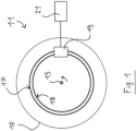
- Fig. 1 shows a schematic diagram of a sensor device 11 in an embodiment as a rotary encoder or encoder, for example for use in a motor feedback system.
- the sensor device 11 has a code disk as a measuring embodiment 15 that is connected to a rotatable shaft 13 in a drive-effective manner.
- the measuring embodiment 15 has a first code track 17 and a second code track 18 running parallel to it.
- the circular code tracks 17, 18 here define an absolute code, as will be explained in more detail below.
- the sensor device 11 has a scanning device 19 that does not rotate with the shaft 13, but is attached to a fixed component (not shown).
- the scanning device 19 is in signal connection with an electronic evaluation unit 21.
- the evaluation unit 21 receives signals from the scanning device 19, reads the absolute code and determines the absolute rotational position of the shaft 13 based on the absolute code.
- the code tracks 17, 18 can have successive areas of different reflectivity, which are detected by optical sensors of the scanning device 19, which in Fig. 1 however, is not shown in detail.
- the code tracks 17, 18 and the scanning device 19 can also interact magnetically, capacitively or inductively, as is generally known.
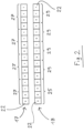
- Fig. 2 shows the first code track 17 and the second code track 18 as an example, in straightened form for simplification, with the code elements 22, i.e. the distinguishable areas of the code tracks 17, 18, being marked with "0" and "1". This means that in the embodiment shown, the code elements correspond to 22 bits.
- the first code track 17 and the second code track 18 have respective individual codes which are based on linear feedback shift registers (LFSR). Fig. 2
- the individual code of the first code track 17 is a "4 ⁇ 2 bit” code with a zero word.
- the individual code of the second code track 18 is a "4 ⁇ 2 bit” code without a zero word.
- the individual code of the second code track 18 is assigned a global zero word 25.
- the first code track 17 is formed by a series of four identical code track segments 27, each four bits long.
- the second code track 18 also comprises four identical code track segments 29, but their length is only 3 bits each due to the missing zero word. Overall, the code tracks 17, 18 are the same length, with the missing positions in the second code track 18 being filled by the global zero word 25.
- two code elements 22 of the first code track 17 and two code elements 22 of the second code track 18 are recognized together by means of the scanning device 19, for which the Scanning device 19 is equipped with two sets of two detectors.
- the two detected bits of the first code track 17 correspond to a code word 35 of the associated individual code.
- the two detected bits of the second code track 18 correspond to a code word 36 of the associated individual code.
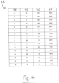
- the evaluation unit 21 As in Fig. 4 shown, the evaluation unit 21 ( Fig. 1 ) the two code words 35, 36 of the individual codes are concatenated to form a code word 37 of the absolute code.
- a lookup table 33 is used to uniquely assign each code word 37 of the absolute code to a position 39, i.e. a position number or a position value.
- the Fig. 3 The position of the scanning device 19 shown corresponds to position 39 with the number 6.
- each of the two individual codes has a binary resolution of two bits.
- the total resolution i.e. the resolution of the absolute code
- the code track segments 27 of the first code track 17 and the code track segments 29 of the second code track 18 are of unequal length, i.e. have an unequal number of bits, a unique 4-bit absolute code can be formed according to the Vernier principle.
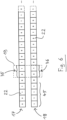
- the absolute code described can be easily scaled. It is not necessary to use the maximum code length. Rather, individual code track segments 27, 29 can be omitted in order to shorten the two code tracks 17, 18. In this way, the measuring embodiment 15 ( Fig. 1 ) can be adapted to a specific application without requiring a redesign of the scanning device 19 or a change in the dimensions of the code elements 22.
- Fig. 5 illustrates this procedure in general.
- a number of m code track segments 27 are omitted from n code track segments 27 of the maximum code length.
- the same number m of code track segments 29 are omitted and in addition the global zero word 25 is shortened by m positions.
- Fig. 6 an alternative embodiment is shown in which a global one word 45 is provided instead of a global zero word.
- Fig. 7 shows a corresponding example, wherein the first code track 17 has a number of (n / 2)-m code track segments 27 and the second code track 18 has a number of n-2m code track segments 29 and additionally a zero word 25 shortened by n-2m positions.
- the individual codes of both code tracks 17, 18 comprise cascaded segments, with each segment containing the entire code.
- the arrangement of the two individual codes relative to one another according to the "vernier principle" establishes the uniqueness of the detection of both individual codes.
- the introduction of the global zero word 25 serves to fill the maximum code length. By shortening the individual codes segment by segment combined with a bit-by-bit shortening of the global zero word 25, the total code length can be scaled segment by segment. By selecting the resolution and dividing this resolution into at least two parallel codes, the maximum code length can in principle be set arbitrarily.
- the code length of a 2x2 bit arrangement can be shortened from 16 to 12 by omitting both the last segment of the first code and the last segment of the second code.
- the first code then only has 12 words, while the second code has 13 words due to the missing zero word in the omitted segment.
- the discrepancy is eliminated by omitting not only one segment in the second code, but also one bit of the global zero word. This means that both individual codes have a length of 12 and are one segment shorter without losing the uniqueness due to the vernier principle.
- the maximum code length is simply no longer fully utilized.
- the global zero word can be omitted instead of the code track segment.
- the shift of the individual codes relative to each other can be arbitrary. Furthermore, the segment-wise shift of the individual codes relative to each other can be more than one bit per segment.
- a sensor device 11 can also be used for determining the position of linearly displaceable components, in which case the code tracks 17, 18 are linear instead of as in Fig. 1 shown are circular.
- the invention provides a scalable absolute coding with segment-by-segment resolution, whereby no different detector units are necessary for different measuring lengths. Only relatively few bits per code track have to be sampled, which leads to a higher mechanical tolerance.
Landscapes
- Physics & Mathematics (AREA)
- General Physics & Mathematics (AREA)
- Transmission And Conversion Of Sensor Element Output (AREA)
Applications Claiming Priority (1)
| Application Number | Priority Date | Filing Date | Title |
|---|---|---|---|
| DE102023118535.7A DE102023118535A1 (de) | 2023-07-13 | 2023-07-13 | Gebervorrichtung |
Publications (2)
| Publication Number | Publication Date |
|---|---|
| EP4492013A1 true EP4492013A1 (fr) | 2025-01-15 |
| EP4492013B1 EP4492013B1 (fr) | 2025-09-10 |
Family
ID=90922384
Family Applications (1)
| Application Number | Title | Priority Date | Filing Date |
|---|---|---|---|
| EP24172641.3A Active EP4492013B1 (fr) | 2023-07-13 | 2024-04-26 | Dispositif de détection |
Country Status (2)
| Country | Link |
|---|---|
| EP (1) | EP4492013B1 (fr) |
| DE (1) | DE102023118535A1 (fr) |
Citations (1)
| Publication number | Priority date | Publication date | Assignee | Title |
|---|---|---|---|---|
| EP2342539B1 (fr) * | 2008-10-30 | 2017-09-06 | Dr. Johannes Heidenhain GmbH | Dispositif de mesure de position absolue |
Family Cites Families (1)
| Publication number | Priority date | Publication date | Assignee | Title |
|---|---|---|---|---|
| DE102008053986A1 (de) * | 2008-10-30 | 2010-05-06 | Dr. Johannes Heidenhain Gmbh | Absolute Winkelcodierung und Winkelmessvorrichtung |
-
2023
- 2023-07-13 DE DE102023118535.7A patent/DE102023118535A1/de active Pending
-
2024
- 2024-04-26 EP EP24172641.3A patent/EP4492013B1/fr active Active
Patent Citations (1)
| Publication number | Priority date | Publication date | Assignee | Title |
|---|---|---|---|---|
| EP2342539B1 (fr) * | 2008-10-30 | 2017-09-06 | Dr. Johannes Heidenhain GmbH | Dispositif de mesure de position absolue |
Also Published As
| Publication number | Publication date |
|---|---|
| EP4492013B1 (fr) | 2025-09-10 |
| DE102023118535A1 (de) | 2025-01-16 |
Similar Documents
| Publication | Publication Date | Title |
|---|---|---|
| EP2072965B1 (fr) | Dispositif de mesure de position et procédé de détermination de la position absolue | |
| EP1202025B1 (fr) | Dispositif de mesure d'angles | |
| EP1821073B1 (fr) | Dispositif de mesure de position | |
| EP2340417B1 (fr) | Dispositif de mesure de position absolue | |
| DE19545949A1 (de) | Digitales Absolutpositions-Codiergerät und Codierverfahren | |
| EP2342540B1 (fr) | Codage d'angle absolu et dispositif de mesure d'angle | |
| EP0991918B1 (fr) | Procede de determination de la position angulaire absolue du volant de direction d'un vehicule a moteur et capteur de l'angle de braquage optoelectronique | |
| EP1557646B1 (fr) | Détecteur d'angle de rotation et procédé de balayage optique d'une disque de code d'un détecteur d'angle de rotation | |
| EP1195579B1 (fr) | Procédé de détermination de la position absolue | |
| DE102021102053B4 (de) | Bestimmung einer Position | |
| EP1206684B1 (fr) | Dispositif de mesure de position | |
| EP2342539B1 (fr) | Dispositif de mesure de position absolue | |
| EP4492013B1 (fr) | Dispositif de détection | |
| DE102021110583B4 (de) | Gebervorrichtung und Verfahren zur Bestimmung einer Absolutposition | |
| EP2340418B1 (fr) | Code d'une position absolu et dispositif de mesure de positions | |
| DE3939353A1 (de) | Messverfahren und -vorrichtung | |
| EP0575663A1 (fr) | Capteur pour produire les signaux électriques, indiquant la position d'un objet | |
| EP3924696B1 (fr) | Dispositif de mesure de position pour mesurer une position absolue | |
| DE9017851U1 (de) | Decodiervorrichtung | |
| DE102017205267A1 (de) | Positionsmesseinrichtung und Verfahren zum Betreiben einer Positionsmesseinrichtung | |
| DE102023134625B3 (de) | Vorrichtung und verfahren zur positions-, längen- oder winkelbestimmung sowie verfahren zur bildung einer entsprechenden codierung | |
| EP0707384A1 (fr) | Dispositif de mesure de position | |
| DE10060185B4 (de) | Vorrichtung und Verfahren zum Messen von Winkeln | |
| DE202023106207U1 (de) | Antrieb mit magnetischer Absolutcodierung | |
| DE202004011508U1 (de) | Drehwinkelgeber |
Legal Events
| Date | Code | Title | Description |
|---|---|---|---|
| PUAI | Public reference made under article 153(3) epc to a published international application that has entered the european phase |
Free format text: ORIGINAL CODE: 0009012 |
|
| STAA | Information on the status of an ep patent application or granted ep patent |
Free format text: STATUS: THE APPLICATION HAS BEEN PUBLISHED |
|
| AK | Designated contracting states |
Kind code of ref document: A1 Designated state(s): AL AT BE BG CH CY CZ DE DK EE ES FI FR GB GR HR HU IE IS IT LI LT LU LV MC ME MK MT NL NO PL PT RO RS SE SI SK SM TR |
|
| STAA | Information on the status of an ep patent application or granted ep patent |
Free format text: STATUS: REQUEST FOR EXAMINATION WAS MADE |
|
| 17P | Request for examination filed |
Effective date: 20250224 |
|
| GRAP | Despatch of communication of intention to grant a patent |
Free format text: ORIGINAL CODE: EPIDOSNIGR1 |
|
| STAA | Information on the status of an ep patent application or granted ep patent |
Free format text: STATUS: GRANT OF PATENT IS INTENDED |
|
| INTG | Intention to grant announced |
Effective date: 20250513 |
|
| GRAS | Grant fee paid |
Free format text: ORIGINAL CODE: EPIDOSNIGR3 |
|
| GRAA | (expected) grant |
Free format text: ORIGINAL CODE: 0009210 |
|
| STAA | Information on the status of an ep patent application or granted ep patent |
Free format text: STATUS: THE PATENT HAS BEEN GRANTED |
|
| AK | Designated contracting states |
Kind code of ref document: B1 Designated state(s): AL AT BE BG CH CY CZ DE DK EE ES FI FR GB GR HR HU IE IS IT LI LT LU LV MC ME MK MT NL NO PL PT RO RS SE SI SK SM TR |
|
| REG | Reference to a national code |
Ref country code: GB Ref legal event code: FG4D Free format text: NOT ENGLISH |
|
| REG | Reference to a national code |
Ref country code: CH Ref legal event code: EP |
|
| REG | Reference to a national code |
Ref country code: DE Ref legal event code: R096 Ref document number: 502024000220 Country of ref document: DE |
|
| REG | Reference to a national code |
Ref country code: IE Ref legal event code: FG4D Free format text: LANGUAGE OF EP DOCUMENT: GERMAN |
|
| PG25 | Lapsed in a contracting state [announced via postgrant information from national office to epo] |
Ref country code: NO Free format text: LAPSE BECAUSE OF FAILURE TO SUBMIT A TRANSLATION OF THE DESCRIPTION OR TO PAY THE FEE WITHIN THE PRESCRIBED TIME-LIMIT Effective date: 20251210 |
|
| REG | Reference to a national code |
Ref country code: LT Ref legal event code: MG9D |
|
| PG25 | Lapsed in a contracting state [announced via postgrant information from national office to epo] |
Ref country code: FI Free format text: LAPSE BECAUSE OF FAILURE TO SUBMIT A TRANSLATION OF THE DESCRIPTION OR TO PAY THE FEE WITHIN THE PRESCRIBED TIME-LIMIT Effective date: 20250910 |
|
| REG | Reference to a national code |
Ref country code: NL Ref legal event code: MP Effective date: 20250910 |
|
| PG25 | Lapsed in a contracting state [announced via postgrant information from national office to epo] |
Ref country code: HR Free format text: LAPSE BECAUSE OF FAILURE TO SUBMIT A TRANSLATION OF THE DESCRIPTION OR TO PAY THE FEE WITHIN THE PRESCRIBED TIME-LIMIT Effective date: 20250910 |
|
| PG25 | Lapsed in a contracting state [announced via postgrant information from national office to epo] |
Ref country code: GR Free format text: LAPSE BECAUSE OF FAILURE TO SUBMIT A TRANSLATION OF THE DESCRIPTION OR TO PAY THE FEE WITHIN THE PRESCRIBED TIME-LIMIT Effective date: 20251211 |
|
| PG25 | Lapsed in a contracting state [announced via postgrant information from national office to epo] |
Ref country code: SE Free format text: LAPSE BECAUSE OF FAILURE TO SUBMIT A TRANSLATION OF THE DESCRIPTION OR TO PAY THE FEE WITHIN THE PRESCRIBED TIME-LIMIT Effective date: 20250910 |
|
| PG25 | Lapsed in a contracting state [announced via postgrant information from national office to epo] |
Ref country code: LV Free format text: LAPSE BECAUSE OF FAILURE TO SUBMIT A TRANSLATION OF THE DESCRIPTION OR TO PAY THE FEE WITHIN THE PRESCRIBED TIME-LIMIT Effective date: 20250910 |
|
| PG25 | Lapsed in a contracting state [announced via postgrant information from national office to epo] |
Ref country code: PL Free format text: LAPSE BECAUSE OF FAILURE TO SUBMIT A TRANSLATION OF THE DESCRIPTION OR TO PAY THE FEE WITHIN THE PRESCRIBED TIME-LIMIT Effective date: 20250910 Ref country code: BG Free format text: LAPSE BECAUSE OF FAILURE TO SUBMIT A TRANSLATION OF THE DESCRIPTION OR TO PAY THE FEE WITHIN THE PRESCRIBED TIME-LIMIT Effective date: 20250910 |
|
| PG25 | Lapsed in a contracting state [announced via postgrant information from national office to epo] |
Ref country code: RS Free format text: LAPSE BECAUSE OF FAILURE TO SUBMIT A TRANSLATION OF THE DESCRIPTION OR TO PAY THE FEE WITHIN THE PRESCRIBED TIME-LIMIT Effective date: 20251210 |
|
| PG25 | Lapsed in a contracting state [announced via postgrant information from national office to epo] |
Ref country code: ES Free format text: LAPSE BECAUSE OF FAILURE TO SUBMIT A TRANSLATION OF THE DESCRIPTION OR TO PAY THE FEE WITHIN THE PRESCRIBED TIME-LIMIT Effective date: 20250910 |
|
| PG25 | Lapsed in a contracting state [announced via postgrant information from national office to epo] |
Ref country code: NL Free format text: LAPSE BECAUSE OF FAILURE TO SUBMIT A TRANSLATION OF THE DESCRIPTION OR TO PAY THE FEE WITHIN THE PRESCRIBED TIME-LIMIT Effective date: 20250910 |
|
| PG25 | Lapsed in a contracting state [announced via postgrant information from national office to epo] |
Ref country code: SM Free format text: LAPSE BECAUSE OF FAILURE TO SUBMIT A TRANSLATION OF THE DESCRIPTION OR TO PAY THE FEE WITHIN THE PRESCRIBED TIME-LIMIT Effective date: 20250910 |
|
| PG25 | Lapsed in a contracting state [announced via postgrant information from national office to epo] |
Ref country code: IS Free format text: LAPSE BECAUSE OF FAILURE TO SUBMIT A TRANSLATION OF THE DESCRIPTION OR TO PAY THE FEE WITHIN THE PRESCRIBED TIME-LIMIT Effective date: 20260110 |
|
| PG25 | Lapsed in a contracting state [announced via postgrant information from national office to epo] |
Ref country code: CZ Free format text: LAPSE BECAUSE OF FAILURE TO SUBMIT A TRANSLATION OF THE DESCRIPTION OR TO PAY THE FEE WITHIN THE PRESCRIBED TIME-LIMIT Effective date: 20250910 Ref country code: PT Free format text: LAPSE BECAUSE OF FAILURE TO SUBMIT A TRANSLATION OF THE DESCRIPTION OR TO PAY THE FEE WITHIN THE PRESCRIBED TIME-LIMIT Effective date: 20260112 |
|
| PG25 | Lapsed in a contracting state [announced via postgrant information from national office to epo] |
Ref country code: EE Free format text: LAPSE BECAUSE OF FAILURE TO SUBMIT A TRANSLATION OF THE DESCRIPTION OR TO PAY THE FEE WITHIN THE PRESCRIBED TIME-LIMIT Effective date: 20250910 Ref country code: SK Free format text: LAPSE BECAUSE OF FAILURE TO SUBMIT A TRANSLATION OF THE DESCRIPTION OR TO PAY THE FEE WITHIN THE PRESCRIBED TIME-LIMIT Effective date: 20250910 |