EP4492084A1 - Verfahren zur verarbeitung von daten an einer maschine mit einer datenbank, in welcher objektdefinitionsdaten von den bezugspunkten entlang einer vorbestimmten verarbeitungsstrecke aufgezeichnet sind, und entsprechendes computerprogrammprodukt - Google Patents
Verfahren zur verarbeitung von daten an einer maschine mit einer datenbank, in welcher objektdefinitionsdaten von den bezugspunkten entlang einer vorbestimmten verarbeitungsstrecke aufgezeichnet sind, und entsprechendes computerprogrammprodukt Download PDFInfo
- Publication number
- EP4492084A1 EP4492084A1 EP24186713.4A EP24186713A EP4492084A1 EP 4492084 A1 EP4492084 A1 EP 4492084A1 EP 24186713 A EP24186713 A EP 24186713A EP 4492084 A1 EP4492084 A1 EP 4492084A1
- Authority
- EP
- European Patent Office
- Prior art keywords
- machine
- constituting
- database
- image
- objects
- Prior art date
- Legal status (The legal status is an assumption and is not a legal conclusion. Google has not performed a legal analysis and makes no representation as to the accuracy of the status listed.)
- Pending
Links
Images



Classifications
-
- G—PHYSICS
- G06—COMPUTING OR CALCULATING; COUNTING
- G06T—IMAGE DATA PROCESSING OR GENERATION, IN GENERAL
- G06T7/00—Image analysis
- G06T7/70—Determining position or orientation of objects or cameras
-
- G—PHYSICS
- G01—MEASURING; TESTING
- G01S—RADIO DIRECTION-FINDING; RADIO NAVIGATION; DETERMINING DISTANCE OR VELOCITY BY USE OF RADIO WAVES; LOCATING OR PRESENCE-DETECTING BY USE OF THE REFLECTION OR RERADIATION OF RADIO WAVES; ANALOGOUS ARRANGEMENTS USING OTHER WAVES
- G01S17/00—Systems using the reflection or reradiation of electromagnetic waves other than radio waves, e.g. lidar systems
- G01S17/86—Combinations of lidar systems with systems other than lidar, radar or sonar, e.g. with direction finders
-
- G—PHYSICS
- G01—MEASURING; TESTING
- G01S—RADIO DIRECTION-FINDING; RADIO NAVIGATION; DETERMINING DISTANCE OR VELOCITY BY USE OF RADIO WAVES; LOCATING OR PRESENCE-DETECTING BY USE OF THE REFLECTION OR RERADIATION OF RADIO WAVES; ANALOGOUS ARRANGEMENTS USING OTHER WAVES
- G01S7/00—Details of systems according to groups G01S13/00, G01S15/00, G01S17/00
- G01S7/02—Details of systems according to groups G01S13/00, G01S15/00, G01S17/00 of systems according to group G01S13/00
- G01S7/41—Details of systems according to groups G01S13/00, G01S15/00, G01S17/00 of systems according to group G01S13/00 using analysis of echo signal for target characterisation; Target signature; Target cross-section
-
- B—PERFORMING OPERATIONS; TRANSPORTING
- B61—RAILWAYS
- B61L—GUIDING RAILWAY TRAFFIC; ENSURING THE SAFETY OF RAILWAY TRAFFIC
- B61L23/00—Control, warning or like safety means along the route or between vehicles or trains
- B61L23/04—Control, warning or like safety means along the route or between vehicles or trains for monitoring the mechanical state of the route
- B61L23/041—Obstacle detection
-
- B—PERFORMING OPERATIONS; TRANSPORTING
- B61—RAILWAYS
- B61L—GUIDING RAILWAY TRAFFIC; ENSURING THE SAFETY OF RAILWAY TRAFFIC
- B61L25/00—Recording or indicating positions or identities of vehicles or trains or setting of track apparatus
- B61L25/02—Indicating or recording positions or identities of vehicles or trains
- B61L25/025—Absolute localisation, e.g. providing geodetic coordinates
-
- G—PHYSICS
- G01—MEASURING; TESTING
- G01C—MEASURING DISTANCES, LEVELS OR BEARINGS; SURVEYING; NAVIGATION; GYROSCOPIC INSTRUMENTS; PHOTOGRAMMETRY OR VIDEOGRAMMETRY
- G01C21/00—Navigation; Navigational instruments not provided for in groups G01C1/00 - G01C19/00
- G01C21/20—Instruments for performing navigational calculations
-
- G—PHYSICS
- G01—MEASURING; TESTING
- G01S—RADIO DIRECTION-FINDING; RADIO NAVIGATION; DETERMINING DISTANCE OR VELOCITY BY USE OF RADIO WAVES; LOCATING OR PRESENCE-DETECTING BY USE OF THE REFLECTION OR RERADIATION OF RADIO WAVES; ANALOGOUS ARRANGEMENTS USING OTHER WAVES
- G01S13/00—Systems using the reflection or reradiation of radio waves, e.g. radar systems; Analogous systems using reflection or reradiation of waves whose nature or wavelength is irrelevant or unspecified
- G01S13/02—Systems using reflection of radio waves, e.g. primary radar systems; Analogous systems
- G01S13/06—Systems determining position data of a target
- G01S13/42—Simultaneous measurement of distance and other co-ordinates
-
- G—PHYSICS
- G01—MEASURING; TESTING
- G01S—RADIO DIRECTION-FINDING; RADIO NAVIGATION; DETERMINING DISTANCE OR VELOCITY BY USE OF RADIO WAVES; LOCATING OR PRESENCE-DETECTING BY USE OF THE REFLECTION OR RERADIATION OF RADIO WAVES; ANALOGOUS ARRANGEMENTS USING OTHER WAVES
- G01S17/00—Systems using the reflection or reradiation of electromagnetic waves other than radio waves, e.g. lidar systems
- G01S17/88—Lidar systems specially adapted for specific applications
- G01S17/89—Lidar systems specially adapted for specific applications for mapping or imaging
-
- G—PHYSICS
- G01—MEASURING; TESTING
- G01S—RADIO DIRECTION-FINDING; RADIO NAVIGATION; DETERMINING DISTANCE OR VELOCITY BY USE OF RADIO WAVES; LOCATING OR PRESENCE-DETECTING BY USE OF THE REFLECTION OR RERADIATION OF RADIO WAVES; ANALOGOUS ARRANGEMENTS USING OTHER WAVES
- G01S17/00—Systems using the reflection or reradiation of electromagnetic waves other than radio waves, e.g. lidar systems
- G01S17/88—Lidar systems specially adapted for specific applications
- G01S17/93—Lidar systems specially adapted for specific applications for anti-collision purposes
- G01S17/931—Lidar systems specially adapted for specific applications for anti-collision purposes of land vehicles
-
- G—PHYSICS
- G01—MEASURING; TESTING
- G01S—RADIO DIRECTION-FINDING; RADIO NAVIGATION; DETERMINING DISTANCE OR VELOCITY BY USE OF RADIO WAVES; LOCATING OR PRESENCE-DETECTING BY USE OF THE REFLECTION OR RERADIATION OF RADIO WAVES; ANALOGOUS ARRANGEMENTS USING OTHER WAVES
- G01S7/00—Details of systems according to groups G01S13/00, G01S15/00, G01S17/00
- G01S7/48—Details of systems according to groups G01S13/00, G01S15/00, G01S17/00 of systems according to group G01S17/00
- G01S7/4802—Details of systems according to groups G01S13/00, G01S15/00, G01S17/00 of systems according to group G01S17/00 using analysis of echo signal for target characterisation; Target signature; Target cross-section
-
- G—PHYSICS
- G06—COMPUTING OR CALCULATING; COUNTING
- G06V—IMAGE OR VIDEO RECOGNITION OR UNDERSTANDING
- G06V10/00—Arrangements for image or video recognition or understanding
- G06V10/70—Arrangements for image or video recognition or understanding using pattern recognition or machine learning
-
- G—PHYSICS
- G06—COMPUTING OR CALCULATING; COUNTING
- G06V—IMAGE OR VIDEO RECOGNITION OR UNDERSTANDING
- G06V20/00—Scenes; Scene-specific elements
- G06V20/40—Scenes; Scene-specific elements in video content
- G06V20/48—Matching video sequences
-
- G—PHYSICS
- G01—MEASURING; TESTING
- G01S—RADIO DIRECTION-FINDING; RADIO NAVIGATION; DETERMINING DISTANCE OR VELOCITY BY USE OF RADIO WAVES; LOCATING OR PRESENCE-DETECTING BY USE OF THE REFLECTION OR RERADIATION OF RADIO WAVES; ANALOGOUS ARRANGEMENTS USING OTHER WAVES
- G01S13/00—Systems using the reflection or reradiation of radio waves, e.g. radar systems; Analogous systems using reflection or reradiation of waves whose nature or wavelength is irrelevant or unspecified
- G01S13/88—Radar or analogous systems specially adapted for specific applications
- G01S13/93—Radar or analogous systems specially adapted for specific applications for anti-collision purposes
- G01S13/931—Radar or analogous systems specially adapted for specific applications for anti-collision purposes of land vehicles
- G01S2013/9328—Rail vehicles
Definitions
- the invention relates to a machine adapted to move on at least one predetermined path, for example a train, performing tasks autonomously, such as autonomous location or obstacle detection.
- a discontinuous localization odometer is capable of performing autonomous localization of the train.
- Markers and beacons are used to perform the discontinuous localization in order to correct the odometer.
- markers and beacons are physical elements that must be installed and maintained.
- GNSS signals cannot be used everywhere: GNSS signals are not received in tunnels, nor on metro lines whose tracks are mostly underground.
- a structure such as a station platform, located very close to the train's clearance contour may be mistakenly considered an obstacle.
- the invention uses existing physical elements or simple geometric figures along the predetermined path, commonly the railway track, and obtains an absolute location from these physical elements.
- the invention relates to a computer program adapted to be recorded in the memory of an electronic data processing device and further comprising a microcomputer, said computer program comprising instructions which, when executed on the microcomputer, cause the steps of a method according to the first aspect of the invention to be implemented.
- such a device is adapted to, on the basis of an approximately estimated location of the machine and to identify on said image an object constituting a landmark according to data defining objects constituting landmarks in the database, determine, among the objects constituting landmarks defined in the database, a subset of the objects constituting landmarks located at most at a threshold distance from said approximately estimated location of the machine;
- the identification of an object constituting a landmark being implemented by the data processing device by considering only the subset determined as comprising the object constituting a landmark to be identified, excluding the objects constituting landmarks not included in the subset.
- the description of the invention is given below relative to an embodiment with a train 1.
- the train 1 is adapted to run on a railway network comprising a plurality of railway tracks.
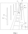
- the Figure 1 represents a schematic view of train 1 running on a railway track comprising rails 21, 22. Train 1 is driven manually or autonomously.
- Train 1 for example, includes a locomotive facing the front part of the track that the train will travel and pulling train cars.
- FIG. 2 represents an electronic processing device 10 on board the train 1.
- the processing device 10 comprises a database 11, a localization block 12 and an image acquisition block 18 comprising a lidar block 13.
- the localization block 12 is adapted to determine the location of the train 1 every time interval of duration T1 (e.g. T1 is in the range from 50 to 500 ms).
- the localization block 12 provides, for example, the absolute location of the train 1 on Earth, for example its absolute 3D coordinates.
- the lidar (Laser Imaging Detection and Ranging) unit 13 is installed on the front of the train's locomotive, and faces the portion of the track ahead of train 1, as shown in Figure 3 .
- the lidar unit 13 comprises at least one laser source adapted to emit laser pulses and comprises sensors. Emitted laser pulses, when they encounter objects, are reflected by these objects: some of these echoes are received by the lidar unit 13 and picked up by the sensors. On the basis of the received echoes measured by the sensors, the lidar unit 13 is adapted to measure the travel time of the laser echoes and to calculate the distance from the source to each reflecting object and also the direction of this object relative to a reference axis, for example the longitudinal axis of the locomotive of the train. A 3D image of the objects in the field of view of the lidar unit 13 can thus be obtained according to an interval T2 (for example T2 is in the range from 50 to 500 ms).
- T2 for example T2 is in the range from 50 to 500 ms.
- the laser source is installed - and the lidar emission is adjusted - so that the lidar field of view covers all objects to be detected along the railway track and which are in the vicinity of the railway track without intrusion.
- the scanning speed of the lidar block 13 influences the number of points and echoes that are measured.
- the choice of optics and scanner has a strong influence on the resolution and range of the lidar system.
- the range of the lidar is the length of the area in front of the train that can be monitored by means of laser waves.
- the database 11 contains data revealing the topology of the railway network, making it possible to know the 3D coordinates of each point of the railway track or at least a precise approximation.
- Database 11 also contains data defining landmark objects that are present along the railway track. These landmark objects are physical objects that are suitable for lidar, i.e. suitable for reflecting incident lidar waves. Examples of types of landmark objects are: a signalling element (with traffic lights), for example 50_2 with reference to Figure 1 ; pylons, for example 50_1; kilometre signs such as 50_3, which indicate a number of kilometres separating the kilometre sign from a reference point; flood barriers; supports with 2D codes; railway platforms; traffic signs, including mileage signs and other indicators; elements having typical geometric figures.
- a signalling element with traffic lights
- pylons for example 50_1
- kilometre signs such as 50_3, which indicate a number of kilometres separating the kilometre sign from a reference point
- flood barriers supports with 2D codes
- railway platforms traffic signs, including mileage signs and other indicators
- elements having typical geometric figures are examples of typical geometric figures.
- the database 11 contains, for each object constituting a defined landmark, its type, its identifier, its coordinates, other attributes such as landmark link information, a direction in which the landmark can be detected, content that can be read at the landmark, etc.
- characteristic attributes of the objects constituting landmarks are recorded: the 3D coordinates of the vertices of the objects in a global geographic reference system linked to the Earth (for example a latitude and a longitude), allowing the objects constituting landmarks to be recognized, and therefore identified, according to the lidar echoes received.
- FIG. 3 represents the steps of a data processing method 100 in one embodiment of the invention accomplishing the localization of the train.
- a preliminary step 100_1 the definition data, including the 3D geographic coordinates of the characteristic point(s) of the objects constituting 50 landmarks along the entire railway track (from the starting point to the final destination point) are determined and are recorded in the database 11.
- objects constituting landmarks can be modeled by standard 3D geometric volumes and/or surfaces associated with geometric parameters including their characteristic dimensions and the coordinates (for example obtained by means of a GNSS receiver or by using mobile topography associated with an inertial unit) of the characteristic vertices of the modeling shape.
- step 100_2 At least one lidar image is acquired according to an interval T2.
- the localization block 12 analyzes an image of a set of images comprising at least the last acquired lidar image, said image being, in one embodiment, the last acquired lidar image, and determines one or more subsets of points in the image corresponding to one or more respective objects that are echo sources. Based on at least said subset of points on said image compared with information of objects constituting landmarks (characteristic vertices, dimensions ...), the localization block 12 searches for the object constituting a landmark in the database 11, finds it and determines all possible identifiers of this landmark represented on the image, given that the landmarks can be almost identical. The train then moves to the next landmark.
- landmarks characteristic vertices, dimensions
- the identifiers of the landmark are further filtered. This process continues until a single landmark can be identified. The location of the train is then determined based on this landmark. At points where trains often make a cold start, landmarks with readable content can be installed, for example a 2D code. In this case, the identifier of the first landmark detected can be read and the location can be determined.
- a subset of the objects constituting landmarks located at most/at least at a first threshold distance (equal to the maximum/minimum speed multiplied by T1) from said last location of the train is extracted from the database 11, and the identification step is performed in comparing the landmark object in the image only to said subset (and not to landmark objects not included in the subset) to identify said landmark object.
- the localization block 12 is adapted to perform, in parallel with the method 100, an approximate estimation of the current location of the train (for example by means of an odometer or an inertial unit) and, knowing a maximum location error associated with this estimation, a subset of the objects constituting landmarks located at most at a second threshold distance from said last location of the train is extracted from the database 11, and the identification step is carried out by comparing the object constituting a landmark on the image only with said subset (and not with the objects constituting landmarks not included in the subset) in order to identify said object constituting a landmark.
- the localization block 12 determines, from the lidar information associated with this object constituting a landmark, the relative distance and direction of the identified object with respect to the train.
- the distance d and the angles ⁇ and ⁇ are determined.
- the localization block 12 extracts from the database 11 the 3D coordinates of the object constituting an identified landmark 50. With reference to the Figure 4 , these coordinates are (x, y, z). And, from these extracted coordinates combined with the distance and relative direction angles, the discrete and absolute location of the train, expressed in 3D coordinates, is calculated.
- the processing device 10 further comprises a video camera 17 placed on the front face of the train 1, for example with (approximately) the same median axis of field of vision as the lidar 13.
- the video camera 17 is adapted to acquire periodic images of the scene in front of the train 1. It is easier to use a camera to distinguish the type of objects detected, by using detection models already highly developed through artificial intelligence.
- step 100_2 the video camera acquires a video image every time interval of duration T3, which is added to the current set of images. And in step 100_3, for example, identification of objects constituting landmarks is performed on the video image. And, in order to ensure that the object constituting a landmark considered on the lidar image in step 100_4 is the same as the object constituting a landmark identified on the video image, a geometric transformation of the 3D lidar image of the set of images is performed to produce a 2D video image; and a matching of image points of the object constituting a landmark identified is then performed, from the video image to the transformed 3D lidar image, this indicating the lidar points to be considered to obtain the distance and direction information.
- the 2D codes are framed with materials having high reflectivity to be better detected by the lidar.
- the 2D code itself contains the same information.
- the lidar block 13 can identify a 2D code type object by detecting, on the lidar images, the 4 vertices of the 2D code, then determining the central point from said vertices using deterministic algorithms.
- the content of the 2D code can be read by the camera block 17.
- the identifier and location of the 2D code can be determined, such that the location of the train can be calculated from the absolute location of the 2D code and the distance from the lidar.
- the train platforms can be detected by the lidar block 13 using deterministic algorithms, such that the two vertices can be identified in step 100_3. With the absolute location of the two vertices from the database 11, the location of the train can be calculated.
- Traffic signs can be detected by lidar using deterministic algorithms by detecting vertices to identify the center point.
- the location of the train can be calculated from the absolute location of the traffic sign and the distance from the lidar.
- Flood barriers are a commonly used means of preventing water from flowing into a station.
- Figure 7 represents a flood barrier and the Figure 8 illustrates the considered characteristics of the flood barrier of the Figure 7 interpreted as a rectangle.
- the two upper extreme vertices are defined as 1_2 and 2_2.
- the two sides of the flood barrier are considered as two landmarks with different vertex coordinates, distinguished by the direction in which the flood barrier is detected.
- Flood barriers can be detected by the lidar using deterministic algorithms, such that the two vertices 1_2, 2_2 can be identified. With the absolute location of the two vertices from the database 11, the location of the train can be calculated. With this information, the detected flood barrier will not be considered as an obstacle intruding into the contour train congestion. Flood barrier detection can also monitor lidar behavior.
- Each figure can represent a number: for example from 0 to 4 when 5 geometric figures are used.
- the corresponding number is deduced by the localization block 12 (the correspondence between each geometric figure and its corresponding number has been previously stored in the database 11).
- a series of figures successively detected by the localization block 12 forms an identifier.
- the information in the database 11 for a series of geometric figures includes the series identifier, associated with the 3D geographic coordinates of each object constituting a figure in the series (or of at least one of the objects, for example that corresponding to the last object encountered in a fixed direction).
- the series of numbers constitutes a serial code. It can be considered as a quinary number where each object represents a number, from 0 to 4, as a digit of the quinary code. If an object is used, it can represent 5 identifiers of length 1, and if, for example, a sequence of 10 objects is used, it can represent 9765625 (5 ⁇ 10) identifiers of length 10. These identifiers are indicated in sequence by the track and the position of the objects is in the database. Once the complete series is detected, the identifier is obtained, which is an index in the database that allows to find the geolocation of the objects that gave rise to the sequence. Thus, from this geolocation, the position of the train can be calculated.
- the lidar is therefore used to detect the type of figure, from which the corresponding number will be deduced. For example:
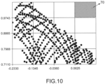
- the geometric objects for example of the type 60_i represented in figure 9 , are arranged one after the other along the track or they can be grouped, as shown in figure 11 , in two examples of a series of geometric objects both "coding" the identifier "131130" (if the convention used, when they are grouped, is that reading is done from top to bottom starting on the left, then from top to bottom on the right).
- Signals and their appearance can be detected by the camera 17.
- a signal is associated with any of the landmarks (with a fixed special distance vector between them, e.g. 0 or different from 0) which can also be detected only by the lidar by detecting the landmark using deterministic algorithms.
- the set of steps 100_2 to 100_4 is repeated every time interval T.
- additional actions 100_5 are optionally performed. For example, based on the determined location or based on a train speed estimated at least based on the determined location, an emergency action is triggered, for example emergency braking. In some embodiments, the additional actions 100_5 are related to obstacle detection and/or assistance with the signal reading function and/or monitoring of the lidar behavior, as described below.
- the processing device 10 comprises an obstacle detection block 14 adapted to detect obstacles around the train 1 and to trigger, on the basis of such detection, emergency actions such as emergency braking.
- Obstacle detection is performed, for example, using lidar images and/or using video images.
- the invention comprises comparing the obstacle estimate with the actual on-site situation defined by the landmark information recorded in the database 11.
- a signal is also a landmark.
- the processing device 10 comprises a signal reading block 15 adapted to identify the signal provided by traffic signaling equipment such as 50_2, for example by determining the location and color of the light emitted by image processing on a video image provided by the camera block 17.
- the signal landmark information in the database 11, e.g. location, possible aspects, can help reduce computational load, e.g. signal detection is only performed from a location within a certain distance of the signal (depending on the detection range, e.g. 200 m) since the signal location is known from the database 11, and as a cross-check reference to improve integrity, whereas without this information the algorithm in the signal reading block 15 would have to constantly search for signals to detect, which consumes considerable computing power. If the aspect of a signal is read, the computer vision must identify the color of the signal (there may be polarized light causing the color to be misread).
- the signal landmark information provides a reference (possible aspects) to check the reading result, for example if the signal aspect is detected as an aspect not included in the list of possible aspects, it is known that the detection is wrong.
- the processing device 10 comprises a lidar monitoring block 16 adapted to monitor the behavior of the lidar block 13, by comparing the landmarks detected in the lidar images and the landmarks in the database 11.
- the processing module 10 performs only one or more of the mentioned methods using landmarks in the database 11 among localization, obstacle detection, assistance with the signal reading function and monitoring the behavior of the lidar.
- the processing device 10 comprises a microprocessor and a memory comprising instructions that, when executed by the microprocessor, cause one or more of the steps 100_1 to 100_5 to be performed.
- a microprocessor and a memory comprising instructions that, when executed by the microprocessor, cause one or more of the steps 100_1 to 100_5 to be performed.
- at least some of the steps may be performed by specialized hardware, commonly a digital integrated circuit, either a specific (ASIC) or based on programmable logic (e.g., FPGA).
- ASIC application specific
- FPGA programmable logic
- lidars Due to performance limitations of lidars, the wider the field of view (FoV), the lower the point density. Therefore, it may not be possible to find a lidar that covers both the distance and the width. Thus, multiple lidars may be used. In one embodiment, at least two lidars are used, instead of just one, for the long distance (FoV1) and short distance (FoV2) respectively to cover the total distance, as illustrated in FIG. Figure 4 Advantages include that both width and distance are covered and the FoV overlap space can be sensed with both/all lidars so as to have independent sensing chains to facilitate the demonstration of the safety level.
- lidar block has been disclosed above with the use of a lidar block.
- Other technologies can be used instead of the lidar, for example radar technology or sonar, or any suitable technology using the detection of echoes of waves generated on board the train.
- the invention has been disclosed above in relation to a train, but it can be used more generally with any machine adapted to move along any trajectory among a set of known trajectories, such a machine being, for example, a metro, a tram, a boat, an airplane, a drone, with or without automatic and autonomous driving.
Landscapes
- Engineering & Computer Science (AREA)
- Physics & Mathematics (AREA)
- Radar, Positioning & Navigation (AREA)
- Remote Sensing (AREA)
- General Physics & Mathematics (AREA)
- Computer Networks & Wireless Communication (AREA)
- Theoretical Computer Science (AREA)
- Electromagnetism (AREA)
- Computer Vision & Pattern Recognition (AREA)
- Multimedia (AREA)
- Mechanical Engineering (AREA)
- Computing Systems (AREA)
- Artificial Intelligence (AREA)
- Databases & Information Systems (AREA)
- Evolutionary Computation (AREA)
- General Health & Medical Sciences (AREA)
- Medical Informatics (AREA)
- Software Systems (AREA)
- Health & Medical Sciences (AREA)
- Automation & Control Theory (AREA)
- Radar Systems Or Details Thereof (AREA)
- Train Traffic Observation, Control, And Security (AREA)
- Image Processing (AREA)
- Image Analysis (AREA)
Applications Claiming Priority (1)
| Application Number | Priority Date | Filing Date | Title |
|---|---|---|---|
| FR2307544A FR3151087B1 (fr) | 2023-07-13 | 2023-07-13 | Prcédé de traitement de données à bord d'une machine et utilisant une base de données dans laquelle sont enregistrées des données de définition d'objets constituant des points de repère le long d'un chemin prédéterminé de la machine |
Publications (1)
| Publication Number | Publication Date |
|---|---|
| EP4492084A1 true EP4492084A1 (de) | 2025-01-15 |
Family
ID=89157818
Family Applications (1)
| Application Number | Title | Priority Date | Filing Date |
|---|---|---|---|
| EP24186713.4A Pending EP4492084A1 (de) | 2023-07-13 | 2024-07-05 | Verfahren zur verarbeitung von daten an einer maschine mit einer datenbank, in welcher objektdefinitionsdaten von den bezugspunkten entlang einer vorbestimmten verarbeitungsstrecke aufgezeichnet sind, und entsprechendes computerprogrammprodukt |
Country Status (5)
| Country | Link |
|---|---|
| US (1) | US20250022159A1 (de) |
| EP (1) | EP4492084A1 (de) |
| CN (1) | CN119310540A (de) |
| CA (1) | CA3246443A1 (de) |
| FR (1) | FR3151087B1 (de) |
Families Citing this family (2)
| Publication number | Priority date | Publication date | Assignee | Title |
|---|---|---|---|---|
| AT524063A1 (de) * | 2020-07-15 | 2022-02-15 | Track Machines Connected Ges M B H | Verteilte und offene Datenbank zur dynamischen Erfassung des Eisenbahnstreckennetzes und dessen Gewerke |
| CN119620040B (zh) * | 2025-02-12 | 2025-04-11 | 成都科瑞特电气自动化有限公司 | 360环视影像辅助的倒车雷达动态障碍物识别方法及系统 |
Citations (3)
| Publication number | Priority date | Publication date | Assignee | Title |
|---|---|---|---|---|
| US20190092360A1 (en) * | 2017-09-27 | 2019-03-28 | Thales Canada Inc | Guideway mounted vehicle localization and alignment system and method |
| EP4099048A1 (de) * | 2021-06-04 | 2022-12-07 | Kabushiki Kaisha Toshiba | Positionsinformationsberechnungsvorrichtung und positionsinformationsberechnungsverfahren |
| US20230202540A1 (en) * | 2020-06-10 | 2023-06-29 | Hitachi, Ltd. | Obstacle detection system, obstacle detection method, and self-location estimation system |
-
2023
- 2023-07-13 FR FR2307544A patent/FR3151087B1/fr active Active
-
2024
- 2024-07-05 EP EP24186713.4A patent/EP4492084A1/de active Pending
- 2024-07-11 CA CA3246443A patent/CA3246443A1/fr active Pending
- 2024-07-12 CN CN202410932079.5A patent/CN119310540A/zh active Pending
- 2024-07-13 US US18/772,121 patent/US20250022159A1/en active Pending
Patent Citations (3)
| Publication number | Priority date | Publication date | Assignee | Title |
|---|---|---|---|---|
| US20190092360A1 (en) * | 2017-09-27 | 2019-03-28 | Thales Canada Inc | Guideway mounted vehicle localization and alignment system and method |
| US20230202540A1 (en) * | 2020-06-10 | 2023-06-29 | Hitachi, Ltd. | Obstacle detection system, obstacle detection method, and self-location estimation system |
| EP4099048A1 (de) * | 2021-06-04 | 2022-12-07 | Kabushiki Kaisha Toshiba | Positionsinformationsberechnungsvorrichtung und positionsinformationsberechnungsverfahren |
Also Published As
| Publication number | Publication date |
|---|---|
| FR3151087B1 (fr) | 2025-11-21 |
| CA3246443A1 (fr) | 2025-06-09 |
| FR3151087A1 (fr) | 2025-01-17 |
| US20250022159A1 (en) | 2025-01-16 |
| CN119310540A (zh) | 2025-01-14 |
Similar Documents
| Publication | Publication Date | Title |
|---|---|---|
| EP4492084A1 (de) | Verfahren zur verarbeitung von daten an einer maschine mit einer datenbank, in welcher objektdefinitionsdaten von den bezugspunkten entlang einer vorbestimmten verarbeitungsstrecke aufgezeichnet sind, und entsprechendes computerprogrammprodukt | |
| KR102657921B1 (ko) | 융합된 이미지를 사용한 엔드 투 엔드 시스템 트레이닝 | |
| CN114274972A (zh) | 自主驾驶环境中的场景识别 | |
| CN110356339B (zh) | 一种变道盲区监测方法、系统及车辆 | |
| CN111341120A (zh) | 一种车辆逆行检测方法、系统及车辆 | |
| US12503134B2 (en) | Method for a scene interpretation of an environment of a vehicle | |
| CN111914691A (zh) | 一种轨道交通车辆定位方法及系统 | |
| CN114771548A (zh) | 用于高级驾驶辅助系统测试和验证的数据记录 | |
| WO2021048471A1 (fr) | Dispositif et procede de localisation autonome d'un vehicule mobile sur une voie ferree | |
| CN119380309B (zh) | 路网生成方法、智能设备及计算可读存储介质 | |
| US20250378264A1 (en) | Automated verification of annotated sensor data | |
| US12282866B2 (en) | Multi-target tracking with dependent likelihood structures | |
| WO2018041978A1 (fr) | Dispositif de détermination d'une limitation de vitesse, système embarqué comprenant un tel dispositif et procédé de détermination d'une limitation de vitesse. | |
| WO2018060381A1 (fr) | Détection d'obstacles pour véhicule automobile | |
| EP0604252B1 (de) | Verfahren zur Steuerungshilfe eines tieffliegenden Flugkörpers | |
| Wender et al. | Extending onboard sensor information by wireless communication | |
| WO2023086170A1 (en) | Unsupervised domain adaptation for lidar segmentation via enhanced pseudo-labeling techniques | |
| FR3151121A1 (fr) | Procédé de détection d'obstacles à bord d'une machine adaptée pour se déplacer sur au moins un chemin prédéterminé | |
| Beer et al. | Towards Feature-Based Low-Latency Localization with Rotating LiDARs | |
| FR3152603A1 (fr) | Système et procédé permettant de déterminer un emplacement d'une position désignée d'un système de véhicules | |
| EP4443197A1 (de) | Integritätssteuerungsverfahren, computerprogramm und vorrichtung dafür | |
| WO2026082854A1 (fr) | Système de navigation autonome d'un véhicule sous-marin, ensemble de navigation et procédé de navigation mis en œuvre par un tel système | |
| Araluce et al. | Infrastructure-Based Smart Positioning System for Automated Shuttles Using 3D Object Detection | |
| WO2025081105A1 (en) | Hierarchical multi-object tracker for auto-labeling | |
| CN120318787A (zh) | 一种用于智能驾驶的数字道路标线处理方法及系统 |
Legal Events
| Date | Code | Title | Description |
|---|---|---|---|
| PUAI | Public reference made under article 153(3) epc to a published international application that has entered the european phase |
Free format text: ORIGINAL CODE: 0009012 |
|
| STAA | Information on the status of an ep patent application or granted ep patent |
Free format text: STATUS: THE APPLICATION HAS BEEN PUBLISHED |
|
| AK | Designated contracting states |
Kind code of ref document: A1 Designated state(s): AL AT BE BG CH CY CZ DE DK EE ES FI FR GB GR HR HU IE IS IT LI LT LU LV MC ME MK MT NL NO PL PT RO RS SE SI SK SM TR |
|
| STAA | Information on the status of an ep patent application or granted ep patent |
Free format text: STATUS: REQUEST FOR EXAMINATION WAS MADE |
|
| 17P | Request for examination filed |
Effective date: 20250630 |