EP4492090A1 - Capteur radar - Google Patents
Capteur radar Download PDFInfo
- Publication number
- EP4492090A1 EP4492090A1 EP24179918.8A EP24179918A EP4492090A1 EP 4492090 A1 EP4492090 A1 EP 4492090A1 EP 24179918 A EP24179918 A EP 24179918A EP 4492090 A1 EP4492090 A1 EP 4492090A1
- Authority
- EP
- European Patent Office
- Prior art keywords
- radar transceiver
- semiconductor chip
- transceiver semiconductor
- antennas
- radar
- Prior art date
- Legal status (The legal status is an assumption and is not a legal conclusion. Google has not performed a legal analysis and makes no representation as to the accuracy of the status listed.)
- Pending
Links
Images


Classifications
-
- G—PHYSICS
- G01—MEASURING; TESTING
- G01S—RADIO DIRECTION-FINDING; RADIO NAVIGATION; DETERMINING DISTANCE OR VELOCITY BY USE OF RADIO WAVES; LOCATING OR PRESENCE-DETECTING BY USE OF THE REFLECTION OR RERADIATION OF RADIO WAVES; ANALOGOUS ARRANGEMENTS USING OTHER WAVES
- G01S13/00—Systems using the reflection or reradiation of radio waves, e.g. radar systems; Analogous systems using reflection or reradiation of waves whose nature or wavelength is irrelevant or unspecified
- G01S13/02—Systems using reflection of radio waves, e.g. primary radar systems; Analogous systems
- G01S13/50—Systems of measurement based on relative movement of target
- G01S13/58—Velocity or trajectory determination systems; Sense-of-movement determination systems
- G01S13/581—Velocity or trajectory determination systems; Sense-of-movement determination systems using transmission of interrupted pulse modulated waves and based upon the Doppler effect resulting from movement of targets
- G01S13/582—Velocity or trajectory determination systems; Sense-of-movement determination systems using transmission of interrupted pulse modulated waves and based upon the Doppler effect resulting from movement of targets adapted for simultaneous range and velocity measurements
-
- G—PHYSICS
- G01—MEASURING; TESTING
- G01S—RADIO DIRECTION-FINDING; RADIO NAVIGATION; DETERMINING DISTANCE OR VELOCITY BY USE OF RADIO WAVES; LOCATING OR PRESENCE-DETECTING BY USE OF THE REFLECTION OR RERADIATION OF RADIO WAVES; ANALOGOUS ARRANGEMENTS USING OTHER WAVES
- G01S7/00—Details of systems according to groups G01S13/00, G01S15/00, G01S17/00
- G01S7/02—Details of systems according to groups G01S13/00, G01S15/00, G01S17/00 of systems according to group G01S13/00
- G01S7/03—Details of HF subsystems specially adapted therefor, e.g. common to transmitter and receiver
- G01S7/032—Constructional details for solid-state radar subsystems
-
- G—PHYSICS
- G01—MEASURING; TESTING
- G01S—RADIO DIRECTION-FINDING; RADIO NAVIGATION; DETERMINING DISTANCE OR VELOCITY BY USE OF RADIO WAVES; LOCATING OR PRESENCE-DETECTING BY USE OF THE REFLECTION OR RERADIATION OF RADIO WAVES; ANALOGOUS ARRANGEMENTS USING OTHER WAVES
- G01S13/00—Systems using the reflection or reradiation of radio waves, e.g. radar systems; Analogous systems using reflection or reradiation of waves whose nature or wavelength is irrelevant or unspecified
- G01S13/02—Systems using reflection of radio waves, e.g. primary radar systems; Analogous systems
- G01S13/06—Systems determining position data of a target
- G01S13/46—Indirect determination of position data
- G01S13/48—Indirect determination of position data using multiple beams at emission or reception
-
- G—PHYSICS
- G01—MEASURING; TESTING
- G01S—RADIO DIRECTION-FINDING; RADIO NAVIGATION; DETERMINING DISTANCE OR VELOCITY BY USE OF RADIO WAVES; LOCATING OR PRESENCE-DETECTING BY USE OF THE REFLECTION OR RERADIATION OF RADIO WAVES; ANALOGOUS ARRANGEMENTS USING OTHER WAVES
- G01S13/00—Systems using the reflection or reradiation of radio waves, e.g. radar systems; Analogous systems using reflection or reradiation of waves whose nature or wavelength is irrelevant or unspecified
- G01S13/87—Combinations of radar systems, e.g. primary radar and secondary radar
-
- G—PHYSICS
- G01—MEASURING; TESTING
- G01S—RADIO DIRECTION-FINDING; RADIO NAVIGATION; DETERMINING DISTANCE OR VELOCITY BY USE OF RADIO WAVES; LOCATING OR PRESENCE-DETECTING BY USE OF THE REFLECTION OR RERADIATION OF RADIO WAVES; ANALOGOUS ARRANGEMENTS USING OTHER WAVES
- G01S13/00—Systems using the reflection or reradiation of radio waves, e.g. radar systems; Analogous systems using reflection or reradiation of waves whose nature or wavelength is irrelevant or unspecified
- G01S13/88—Radar or analogous systems specially adapted for specific applications
- G01S13/93—Radar or analogous systems specially adapted for specific applications for anti-collision purposes
- G01S13/931—Radar or analogous systems specially adapted for specific applications for anti-collision purposes of land vehicles
Definitions
- the present invention relates to a radar sensor according to the preamble of claim 1.
- the present invention relates to a radar sensor with a high angular resolution.
- Radar sensors can detect objects in a detection area and measure their relative position in distance and angle to the sensor. For example, a radial speed can also be measured
- the radar sensor sends out electromagnetic signals and their reflections on objects, i.e. echoes, are received and evaluated.
- Single Input Multiple Output is the name given to systems with a single transmitting antenna (input) and multiple receiving antennas (output).
- MISO Multiple Input Single Output
- MIMO Multiple Input Multiple Output
- each transmitting antenna of each radar transceiver chip can be combined with each receiving antenna of each radar transceiver chip.
- 6 x 8 48 virtual antennas with only fourteen (2 x (3+4)) physical individual antennas.
- An object of the invention is to provide an improved and less expensive radar sensor which uses several spatially distributed transmitting antennas and receiving antennas and compares the phase position of the received echo signal at the spatially distributed antennas in order to deduce the angle.
- a radar sensor with at least one first radar transceiver semiconductor chip and at least one second radar transceiver semiconductor chip, wherein the first radar transceiver semiconductor chip has at least two transmitting antennas and at least two receiving antennas, wherein the second radar transceiver semiconductor chip has at least two transmitting antennas and at least two receiving antennas, wherein each radar transceiver semiconductor chip has a carrier frequency, wherein the first radar transceiver semiconductor chip and the second radar transceiver semiconductor chip have a common control and evaluation unit, wherein the control and evaluation unit is designed to control and evaluate the transmitting antennas and receiving antennas of the first radar transceiver semiconductor chip and the control and evaluation unit is designed to control and evaluate the transmitting antennas and receiving antennas of the second radar transceiver semiconductor chip, wherein the carrier frequencies between the radar transceiver semiconductor chips are not synchronized, whereby the first radar transceiver semiconductor chip and the second radar transceiver semiconductor chip do not have a common radio frequency base.
- the radar transceiver semiconductor chip can also be referred to as a radar transceiver semiconductor component.
- MIMO Multiple Input Multiple Output
- the radar transceiver semiconductor chip has two, three, four, five, six, seven or more transmitting antennas.
- the radar transceiver semiconductor chip has two, three, four, five, six, seven or more receiving antennas.
- the number of transmitting antennas and the number of receiving antennas may be different.
- the radar transceiver semiconductor chip has three transmitting antennas and four receiving antennas - a total of seven physical antennas.
- a radar transceiver semiconductor chip IWR6843AOP from Texas Instruments for 60 GHz that is suitable for the invention, with the antennas already arranged on the chip package with, for example, three transmitting antennas and four receiving antennas.
- the big advantage is that no high-frequency design on a circuit board and no separate antenna development is required.
- At least two such or similar radar transceiver semiconductor chips are combined without synchronizing them.
- the radar sensor is easily scalable during development. For example, not only two radar transceiver semiconductor chips are used, but in principle as many as are necessary, i.e. also a plurality or a large number of radar transceiver semiconductor chips that are combined.
- the spatial positioning of the radar transceiver semiconductor chips relative to each other is important.
- the arrangement and positioning of the radar transceiver semiconductor chips or the transmitting and receiving antennas on the radar transceiver semiconductor chips determines how much angular resolution is achieved in the horizontal and vertical directions.
- the twelve received signals create a virtual array that corresponds in all properties to a phased array with a single transmitting antenna and twelve receiving antennas. Accordingly, the signals can be evaluated in the same way as in a classic phased array.
- the phase position of the signals is compared to one another in order to be able to determine the angle. For example, with a Fast Fourier Transformation (FFT) across all received signals.
- FFT Fast Fourier Transformation
- a phased array antenna is a phased array antenna with a strong directivity that focuses the radiation energy by arranging and connecting individual radiators. If the individual radiators can be controlled differently, the antenna pattern can be electronically swiveled (electronic beam swiveling).
- the signal received by the radar sensor or radar device is basically a temporal sequence of pulses whose amplitude and phase can be measured.
- Doppler frequency processing is also based on a measurement of the portion of the frequency spectrum of the received signal.
- the frequency portion of the time-related signal is determined by the Fourier transformation.
- the Fourier transformation has become a fundamental method in signal processing, since a radar echo contains a large amount of information in the signal form. This information is converted by the Fourier transformation into a data format that can be used for computer-aided further processing in the control and evaluation unit.
- a Fast Fourier Transformation (depending on the number of samples) often requires less than a hundredth of the computing time of a Discrete Fourier Transformation.
- Fast Fourier Analysis entire signal forms of radar echoes can be stored as just a few pieces of data during automatic object detection.
- the Fourier transform is a form of analysis that breaks down a function into sine and cosine components (basis functions), that is, into a sum of sine or cosine functions of different frequency, phase and amplitude. To distinguish it from the Fast Fourier Transform (FFT), this analysis is called the Discrete Fourier Transform (DFT).
- FFT Fast Fourier Transform
- DFT Discrete Fourier Transform
- the transmitting antenna and the receiving antenna In order to receive the echo signal of the signal sent out by a transmitting antenna with any receiving antenna, the transmitting antenna and the receiving antenna must be HF-synchronized. With pulse radar they need the same local oscillator, with FMCW radar the current transmitting signal must be present at the receiver.
- synchronization takes place internally on the radar transceiver semiconductor chip. If you want to increase the number of transmitters and receivers further, you will eventually reach the limit that a single chip can never provide an unlimited number of transmitters and receivers. According to the invention, two or more radar transceiver semiconductor chips are then used to further enlarge the virtual array and increase the angular resolution.
- the first radar transceiver semiconductor chip and the second radar transceiver semiconductor chip are cascaded and the control and evaluation unit is integrated in at least one radar transceiver semiconductor chip.
- the radar transceiver semiconductor chips contain the signal processing, i.e. the control and evaluation unit (e.g. a digital signal processor (DSP) in addition to the analog transmission and reception structures), Each radar transceiver semiconductor chip processes the signal as if it were alone, except for the angle evaluation. In an FMCW (frequency modulated continuous wave radar) system, this would basically be a range fast Fourier transform and a Doppler fast Fourier transform and then a constant false alarm rate (CFAR) detection (separating peaks in the signal from the noise). Each radar transceiver semiconductor chip then produces a list of targets or detected objects with distance and radial velocity (Doppler frequency) and a complex amplitude.
- the control and evaluation unit e.g. a digital signal processor (DSP) in addition to the analog transmission and reception structures
- DSP digital signal processor
- Each radar transceiver semiconductor chip processes the signal as if it were alone, except for the angle evaluation. In an FMCW (frequency modulated continuous wave radar) system, this would basically be a range fast
- One of the radar transceiver semiconductor chips is now the master, for example, and collects the object lists or target lists of all other radar transceiver semiconductor chips (e.g. via a serial peripheral interface (SPI). For each object that was detected by all radar transceiver semiconductor chips (same distance and radial velocity), a fast Fourier transformation is then calculated over all complex amplitudes (a fast Fourier transformation over, for example, 24 complex received signals). This results in a final high-resolution angle to the detected object.
- SPI serial peripheral interface
- the interconnection between the radar transceiver semiconductor chips is only a communication interface for data exchange. No other interconnection between the radar transceiver semiconductor chips is necessary.
- the first radar transceiver semiconductor chip and the second radar transceiver semiconductor chip are connected to the common control and evaluation unit.
- control and evaluation unit or the signal processing is arranged outside of the individual radar transceiver semiconductor chip centrally in the control and evaluation unit.
- control and evaluation unit is a digital signal processor.
- CFAR constant false alarm rate
- the radar transceiver semiconductor chips are electronically connected in series.
- One of the radar transceiver semiconductor chips is the master and collects (e.g. via a serial peripheral interface (SPI)) the object lists or target lists of all other radar transceiver semiconductor chips.
- SPI serial peripheral interface
- the interconnection between the radar transceiver semiconductor chips is only a communication interface for data exchange. No other interconnection between the radar transceiver semiconductor chips is necessary.
- control and evaluation unit is designed to evaluate the transmitting antenna and the receiving antenna for an angle evaluation.
- an evaluation is carried out either initially in each radar transceiver semiconductor chip individually and after range fast Fourier transformation, Doppler fast Fourier transformation and constant false alarm rate (CFAR) detection, all results are summarized by the control and evaluation unit and transmitted via, for example, a serial peripheral interface (SPI) to a control and evaluation unit as the master radar transceiver semiconductor chip in which the angle fast Fourier transformation is then calculated for all objects. Or all radar transceiver semiconductor chips calculate centrally and then detection only takes place after all fast Fourier transformations (range Doppler angle).
- SPI serial peripheral interface
- At least three radar transceiver semiconductor chips are arranged, wherein the radar transceiver semiconductor chips are arranged geometrically flat in one plane.
- each radar transceiver semiconductor chip can be arranged.
- the more antennas or the larger the antenna system the more angular resolution is achieved. This is always an advantage, as the angular resolution is improved.
- a division into angular resolution in horizontal and/or vertical direction is possible with various geometric arrangements.
- the three radar transceiver semiconductor chips are arranged geometrically in a matrix shape in horizontal and vertical directions.
- each radar transceiver semiconductor chip can be arranged.
- the more antennas or the larger the antenna system the more angular resolution is achieved. This is always an advantage, as the angular resolution is improved.
- a division into angular resolution in horizontal and/or vertical direction is possible with various geometric arrangements.
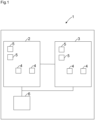
- Figure 1 shows a radar sensor 1 with at least one first radar transceiver semiconductor chip 2 and at least one second radar transceiver semiconductor chip 3, wherein the first radar transceiver semiconductor chip 2 has at least two transmitting antennas 4 and at least two receiving antennas 5, wherein the second radar transceiver semiconductor chip 2 has at least two transmitting antennas 4 and at least two receiving antennas 5, wherein each radar transceiver semiconductor chip 2 has a carrier frequency, wherein the first radar transceiver semiconductor chip 2 and the second radar transceiver semiconductor chip 3 have a common control and evaluation unit 6, wherein the control and evaluation unit 6 is designed to control and evaluate the transmitting antennas 4 and receiving antennas 5 of the first radar transceiver semiconductor chip 2 and the control and evaluation unit 6 is designed to control and evaluate the transmitting antennas 4 and receiving antennas 5 of the second radar transceiver semiconductor chip 3, wherein the carrier frequencies between the radar transceiver semiconductor chips 2, 3 are not synchronized, whereby the first radar transceiver semiconductor chip 2 and the second radar transceiver
- the radar transceiver semiconductor chip 2, 3 has two, three, four, five, six, seven or more transmitting antennas 4.
- the radar transceiver semiconductor chip 2, 3 has two, three, four, five, six, seven or more receiving antennas 5.
- the number of transmitting antennas 4 and the number of receiving antennas 5 can be different.
- the radar transceiver semiconductor chip 2, 3 has three transmitting antennas 4 and four receiving antennas 5 - a total of seven physical antennas.
- a radar transceiver semiconductor chip IWR6843AOP from Texas Instruments suitable for the invention for e.g. 60 GHz, where the antennas are already arranged on the semiconductor chip package with, for example, three transmitting antennas 4 and four receiving antennas 5.
- At least two such or similar radar transceiver semiconductor chips 2, 3 are combined without synchronizing them.
- a complex high-frequency synchronization line is therefore not required between the radar transceiver semiconductor chips 2, 3. There is therefore no synchronization between the radar transceiver semiconductor chips 2, 3. This means that it is not possible to combine the transmitter antennas 4 of one radar transceiver semiconductor chip 2 with the receiver antennas 5 of the other radar transceiver semiconductor chip 3.
- a radar sensor 1 is provided with several transmitting antennas 4 and several receiving antennas 5. For each combination of transmitting antenna 4 and receiving antenna 5, a receiving signal is obtained. According to the following example, three transmitting antennas 4 and four receiving antennas 5 result in twelve receiving signals.
- the twelve received signals create a virtual array that corresponds in all properties to a phased array with a single transmitting antenna 4 and twelve receiving antennas 5. Accordingly, the signals can be evaluated in the same way as in a classic phased array.
- the phase position of the signals is compared to one another in order to be able to determine the angle. For example, with a Fast Fourier Transformation (FFT) across all received signals.
- FFT Fast Fourier Transformation
- the first radar transceiver semiconductor chip 2 and the second radar transceiver semiconductor chip 3 are cascaded and the control and evaluation unit 6 is integrated in at least one radar transceiver semiconductor chip 2, 3.
- each radar transceiver semiconductor chip 2, 3 calculates the signal processing for itself as if it were alone, except for the angle evaluation.
- the control and evaluation unit 6 e.g. a digital signal processor (DSP) in addition to the analog transmission and reception structures
- each radar transceiver semiconductor chip 2, 3 calculates the signal processing for itself as if it were alone, except for the angle evaluation.
- FMCW frequency modulated continuous wave radar
- CFAR constant false alarm rate
- One of the radar transceiver semiconductor chips 2, 3 is now the master, for example, and collects the object lists or target lists of all other radar transceiver semiconductor chips 2, 3 (e.g. via a serial peripheral interface (SPI) interface). For each object that was detected by all radar transceiver semiconductor chips 2, 3 (same distance and radial velocity), a fast Fourier transformation is then calculated over all complex amplitudes (a fast Fourier transformation over, for example, 24 complex received signals). This results in a final high-resolution angle to the detected object.
- SPI serial peripheral interface
- the interconnection between the radar transceiver semiconductor chips 2, 3 is only a communication interface for data exchange. No other interconnection between the radar transceiver semiconductor chips 2, 3 is necessary.
- the first radar transceiver semiconductor chip 2 and the second radar transceiver semiconductor chip 3 are connected to the common control and evaluation unit 6.
- control and evaluation unit 6 or the signal processing outside of the individual radar transceiver semiconductor chips 2, 3 is arranged centrally in the control and evaluation unit 6.
- the control and evaluation unit 6 is a digital signal processor.
- CFAR constant false alarm rate
- the radar transceiver semiconductor chips 2, 3 are electronically connected in series.
- One of the radar transceiver semiconductor chips 2, 3 is the master and collects (e.g. via a serial peripheral interface (SPI)) the object lists or target lists of all other radar transceiver semiconductor chips 2, 3.
- SPI serial peripheral interface
- the interconnection between the radar transceiver semiconductor chips 2, 3 is only a communication interface for data exchange. No other interconnection between the radar transceiver semiconductor chips 2, 3 is necessary.
- control and evaluation unit 6 is designed to evaluate the transmit antennas 4 and receive antennas 5 for an angle evaluation.
- An evaluation takes place as described above either initially in each radar transceiver semiconductor chip 2, 3 individually and after range fast Fourier transformation, Doppler fast Fourier transformation and constant false alarm rate (CFAR) detection, all results are summarized by the control and evaluation unit 6 and transmitted via, for example, a serial peripheral interface (SPI) to a control and evaluation unit 6 as the master radar transceiver semiconductor chip 2, 3 in which the angle fast Fourier transformation is then calculated for all objects.
- SPI serial peripheral interface
- all radar transceiver semiconductor chips 2, 3 calculate centrally and then detection only takes place after all fast Fourier transformations (range Doppler angle).
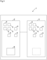
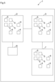
- At least three radar transceiver semiconductor chips 2, 3, 7 are arranged, wherein the radar transceiver semiconductor chips 2, 3, 7 are arranged geometrically flat in one plane.
- each radar transceiver semiconductor chip 2, 3, 7, can be arranged.
- the more antennas, or the larger the antenna system the more angular resolution is achieved. This is always an advantage, as the angular resolution is improved.
- a division into angular resolution in horizontal and/or vertical direction is possible with various geometric arrangements.
- the three radar transceiver semiconductor chips 2, 3, 7 are geometrically arranged in a matrix shape in the horizontal and vertical directions.
Landscapes
- Engineering & Computer Science (AREA)
- Radar, Positioning & Navigation (AREA)
- Remote Sensing (AREA)
- Physics & Mathematics (AREA)
- Computer Networks & Wireless Communication (AREA)
- General Physics & Mathematics (AREA)
- Electromagnetism (AREA)
- Radar Systems Or Details Thereof (AREA)
Applications Claiming Priority (1)
| Application Number | Priority Date | Filing Date | Title |
|---|---|---|---|
| DE102023118328.1A DE102023118328A1 (de) | 2023-07-11 | 2023-07-11 | Radarsensor |
Publications (1)
| Publication Number | Publication Date |
|---|---|
| EP4492090A1 true EP4492090A1 (fr) | 2025-01-15 |
Family
ID=91376775
Family Applications (1)
| Application Number | Title | Priority Date | Filing Date |
|---|---|---|---|
| EP24179918.8A Pending EP4492090A1 (fr) | 2023-07-11 | 2024-06-04 | Capteur radar |
Country Status (3)
| Country | Link |
|---|---|
| US (1) | US20250020767A1 (fr) |
| EP (1) | EP4492090A1 (fr) |
| DE (1) | DE102023118328A1 (fr) |
Citations (3)
| Publication number | Priority date | Publication date | Assignee | Title |
|---|---|---|---|---|
| US20160018511A1 (en) * | 2014-07-17 | 2016-01-21 | Texas Instruments Incorporated | Distributed Radar Signal Processing in a Radar System |
| DE102015218542A1 (de) * | 2015-09-28 | 2017-03-30 | Robert Bosch Gmbh | Integrierter Hochfrequenzschaltkreis, Radarsensor und Betriebsverfahren |
| DE102021207201A1 (de) * | 2021-07-08 | 2023-01-12 | Robert Bosch Gesellschaft mit beschränkter Haftung | Radarsystem für Kraftfahrzeuge |
Family Cites Families (12)
| Publication number | Priority date | Publication date | Assignee | Title |
|---|---|---|---|---|
| FR2950147B1 (fr) * | 2009-09-15 | 2012-07-13 | Thales Sa | Radar a agilite de faisceau, notamment pour la fonction de detection et d'evitement d'obstacles |
| US8797208B2 (en) * | 2010-12-13 | 2014-08-05 | Sony Corporation | Active radar system and method |
| JP6377000B2 (ja) * | 2015-03-25 | 2018-08-22 | パナソニック株式会社 | レーダ装置 |
| US10061015B2 (en) * | 2015-09-30 | 2018-08-28 | Texas Instruments Incorporated | Multi-chip transceiver testing in a radar system |
| US10261179B2 (en) * | 2016-04-07 | 2019-04-16 | Uhnder, Inc. | Software defined automotive radar |
| WO2017187306A1 (fr) * | 2016-04-25 | 2017-11-02 | Uhnder, Inc. | Filtrage adaptatif pour atténuation d'interférence fmcw dans des systèmes de radar pmcw |
| DE102019115107B3 (de) * | 2019-06-05 | 2020-09-24 | Infineon Technologies Ag | Radar-system mit mehreren radar chips |
| US11953615B2 (en) * | 2020-01-13 | 2024-04-09 | Uhnder Inc. | Method and system for antenna array calibration for cross-coupling and gain/phase variations in radar systems |
| DE102020109611B4 (de) * | 2020-04-07 | 2022-01-05 | Infineon Technologies Ag | Radarsystem mit balancing der empfangskanäle über mehrere radar-chips |
| US12007462B2 (en) * | 2020-10-16 | 2024-06-11 | Texas Instruments Incorporated | Non-uniform multi-dimensional data access for radar data processing |
| KR102791137B1 (ko) * | 2021-10-12 | 2025-04-07 | 주식회사 에이티코디 | 입체 감지용 광각 레이다 모듈 |
| EP4328624A1 (fr) * | 2022-08-24 | 2024-02-28 | GM Cruise Holdings LLC | Synchronisation radar à puces multiples |
-
2023
- 2023-07-11 DE DE102023118328.1A patent/DE102023118328A1/de active Pending
-
2024
- 2024-06-04 EP EP24179918.8A patent/EP4492090A1/fr active Pending
- 2024-07-10 US US18/768,670 patent/US20250020767A1/en active Pending
Patent Citations (3)
| Publication number | Priority date | Publication date | Assignee | Title |
|---|---|---|---|---|
| US20160018511A1 (en) * | 2014-07-17 | 2016-01-21 | Texas Instruments Incorporated | Distributed Radar Signal Processing in a Radar System |
| DE102015218542A1 (de) * | 2015-09-28 | 2017-03-30 | Robert Bosch Gmbh | Integrierter Hochfrequenzschaltkreis, Radarsensor und Betriebsverfahren |
| DE102021207201A1 (de) * | 2021-07-08 | 2023-01-12 | Robert Bosch Gesellschaft mit beschränkter Haftung | Radarsystem für Kraftfahrzeuge |
Non-Patent Citations (1)
| Title |
|---|
| ANONYMOUS: "IWR6843AOP Single-Chip 60-to 64-GHz mmWave Sensor Antennas-On-Package (AOP)", TEXAS INSTRUMENTS, 1 January 2022 (2022-01-01), pages 1 - 81, XP093178027, Retrieved from the Internet <URL:https://www.ti.com/lit/gpn/iwr6843aop> * |
Also Published As
| Publication number | Publication date |
|---|---|
| US20250020767A1 (en) | 2025-01-16 |
| DE102023118328A1 (de) | 2025-01-16 |
Similar Documents
| Publication | Publication Date | Title |
|---|---|---|
| DE102018132745B4 (de) | Fmcw radar mit störsignalunterdrückung im zeitbereich | |
| EP3014297B1 (fr) | Détecteur à radar fmcw à résolution angulaire | |
| DE69700875T2 (de) | Kollisionswarnsystem | |
| EP3204788B1 (fr) | Capteur radar formeur d'image avec formation numérique horizontale de faisceau et mesure verticale d'objet par comparaison de phases en cas d'émetteurs décalés les uns par rapport aux autres | |
| DE69923815T2 (de) | FM-CW Radarvorrichtung | |
| EP3673292B1 (fr) | Système radar d'imagerie avec un réseau de récepteurs pour la détermination de l'angle d'objets en deux dimensions par une disposition étalée des antennes de réception dans une dimension | |
| DE10258367A1 (de) | Mehrzielfähiges Verfahren und mehrzielfähige Sensorvorrichtung für die Abstands- und Winkelortung von Zielobjekten im Nahbereich | |
| EP2769236B1 (fr) | Capteur radar à résolution angulaire | |
| WO2017148561A1 (fr) | Système de radar, comportant un ensemble d'antennes pour émettre et recevoir un rayonnement électromagnétique | |
| EP3596499B1 (fr) | Procédé destiné à déterminer une distance et une vitesse d'un objet | |
| EP3467450A1 (fr) | Appareil de mesure de niveau de remplissage à radar pourvu d'un système radar sur puce | |
| DE102018217110A1 (de) | Radarsystem, sowie eine geeignete Verwendung und Verfahren hierfür | |
| WO2019219262A1 (fr) | Détecteur radar à entrées et sorties multiples (mimo) pour véhicules automobiles | |
| DE102023208463A1 (de) | Verfahren zum Bestimmen von Zielinformationen von Radarzielen eines Radarsystems, sowie Radarsystem und Fahrzeug mit einem entsprechenden Radarsystem | |
| DE112018004001T5 (de) | Radarvorrichtung und automobil mit derselben | |
| EP2005209B1 (fr) | Procédé et dispositif de saisie d'un ou de plusieurs objets dans l'environnement d'un véhicule à moteur | |
| DE102015221163A1 (de) | Verfahren und Vorrichtung zur Verfolgung von Objekten, insbesondere sich bewegenden Objekten, in den dreidimensionalen Raum von abbildenden Radarsensoren | |
| EP0487940B1 (fr) | Radar du type pulsdoppler | |
| DE102008011889A1 (de) | Digitale Strahlformung mit frequenzmodulierten Signalen | |
| DE69519753T2 (de) | Erfassung von Spreizspektrumsignalen | |
| DE102023205823A1 (de) | Verfahren zum entwerfen eines radoms einer radarvorrichtung, radom und radarvorrichtung, für die es verwendet wird | |
| EP4492090A1 (fr) | Capteur radar | |
| DE3731559A1 (de) | Verfahren und anordnung zur radarzielentdeckung und -klassifizierung | |
| DE202023103871U1 (de) | Radarsensor | |
| DE102019219649A1 (de) | Kooperatives Radarsensorsystem mit winkelauflösenden Radarsensoren |
Legal Events
| Date | Code | Title | Description |
|---|---|---|---|
| PUAI | Public reference made under article 153(3) epc to a published international application that has entered the european phase |
Free format text: ORIGINAL CODE: 0009012 |
|
| STAA | Information on the status of an ep patent application or granted ep patent |
Free format text: STATUS: THE APPLICATION HAS BEEN PUBLISHED |
|
| AK | Designated contracting states |
Kind code of ref document: A1 Designated state(s): AL AT BE BG CH CY CZ DE DK EE ES FI FR GB GR HR HU IE IS IT LI LT LU LV MC ME MK MT NL NO PL PT RO RS SE SI SK SM TR |
|
| STAA | Information on the status of an ep patent application or granted ep patent |
Free format text: STATUS: REQUEST FOR EXAMINATION WAS MADE |
|
| 17P | Request for examination filed |
Effective date: 20250415 |
|
| STAA | Information on the status of an ep patent application or granted ep patent |
Free format text: STATUS: EXAMINATION IS IN PROGRESS |
|
| 17Q | First examination report despatched |
Effective date: 20250630 |