EP4492889A1 - Verfahren zur bestimmung von ressourcenkonfigurationsinformationen eines sounding-referenzsignals (srs) und vorrichtung damit - Google Patents
Verfahren zur bestimmung von ressourcenkonfigurationsinformationen eines sounding-referenzsignals (srs) und vorrichtung damit Download PDFInfo
- Publication number
- EP4492889A1 EP4492889A1 EP22930222.9A EP22930222A EP4492889A1 EP 4492889 A1 EP4492889 A1 EP 4492889A1 EP 22930222 A EP22930222 A EP 22930222A EP 4492889 A1 EP4492889 A1 EP 4492889A1
- Authority
- EP
- European Patent Office
- Prior art keywords
- srs resource
- terminal
- periodic
- antenna
- srs
- Prior art date
- Legal status (The legal status is an assumption and is not a legal conclusion. Google has not performed a legal analysis and makes no representation as to the accuracy of the status listed.)
- Pending
Links
Images


Classifications
-
- H—ELECTRICITY
- H04—ELECTRIC COMMUNICATION TECHNIQUE
- H04L—TRANSMISSION OF DIGITAL INFORMATION, e.g. TELEGRAPHIC COMMUNICATION
- H04L5/00—Arrangements affording multiple use of the transmission path
- H04L5/0091—Signalling for the administration of the divided path, e.g. signalling of configuration information
- H04L5/0096—Indication of changes in allocation
-
- H—ELECTRICITY
- H04—ELECTRIC COMMUNICATION TECHNIQUE
- H04B—TRANSMISSION
- H04B7/00—Radio transmission systems, i.e. using radiation field
- H04B7/02—Diversity systems; Multi-antenna system, i.e. transmission or reception using multiple antennas
- H04B7/04—Diversity systems; Multi-antenna system, i.e. transmission or reception using multiple antennas using two or more spaced independent antennas
- H04B7/06—Diversity systems; Multi-antenna system, i.e. transmission or reception using multiple antennas using two or more spaced independent antennas at the transmitting station
- H04B7/0602—Diversity systems; Multi-antenna system, i.e. transmission or reception using multiple antennas using two or more spaced independent antennas at the transmitting station using antenna switching
- H04B7/0608—Antenna selection according to transmission parameters
-
- H—ELECTRICITY
- H04—ELECTRIC COMMUNICATION TECHNIQUE
- H04L—TRANSMISSION OF DIGITAL INFORMATION, e.g. TELEGRAPHIC COMMUNICATION
- H04L5/00—Arrangements affording multiple use of the transmission path
- H04L5/003—Arrangements for allocating sub-channels of the transmission path
- H04L5/0048—Allocation of pilot signals, i.e. of signals known to the receiver
-
- H—ELECTRICITY
- H04—ELECTRIC COMMUNICATION TECHNIQUE
- H04L—TRANSMISSION OF DIGITAL INFORMATION, e.g. TELEGRAPHIC COMMUNICATION
- H04L25/00—Baseband systems
- H04L25/02—Details ; arrangements for supplying electrical power along data transmission lines
- H04L25/0202—Channel estimation
- H04L25/0224—Channel estimation using sounding signals
- H04L25/0226—Channel estimation using sounding signals sounding signals per se
-
- H—ELECTRICITY
- H04—ELECTRIC COMMUNICATION TECHNIQUE
- H04L—TRANSMISSION OF DIGITAL INFORMATION, e.g. TELEGRAPHIC COMMUNICATION
- H04L5/00—Arrangements affording multiple use of the transmission path
- H04L5/0001—Arrangements for dividing the transmission path
- H04L5/0014—Three-dimensional division
- H04L5/0023—Time-frequency-space
-
- H—ELECTRICITY
- H04—ELECTRIC COMMUNICATION TECHNIQUE
- H04L—TRANSMISSION OF DIGITAL INFORMATION, e.g. TELEGRAPHIC COMMUNICATION
- H04L5/00—Arrangements affording multiple use of the transmission path
- H04L5/003—Arrangements for allocating sub-channels of the transmission path
- H04L5/0048—Allocation of pilot signals, i.e. of signals known to the receiver
- H04L5/0051—Allocation of pilot signals, i.e. of signals known to the receiver of dedicated pilots, i.e. pilots destined for a single user or terminal
-
- H—ELECTRICITY
- H04—ELECTRIC COMMUNICATION TECHNIQUE
- H04L—TRANSMISSION OF DIGITAL INFORMATION, e.g. TELEGRAPHIC COMMUNICATION
- H04L5/00—Arrangements affording multiple use of the transmission path
- H04L5/0091—Signalling for the administration of the divided path, e.g. signalling of configuration information
- H04L5/0094—Indication of how sub-channels of the path are allocated
Definitions
- the invention relates to a field of wireless communication technologies, in particular to a method and an apparatus for determining sounding reference signal (SRS) resource configuration information.
- SRS sounding reference signal
- a network device configures an uplink resource for transmitting a sounding reference signal (SRS) for a terminal, so that the terminal can send the SRS on the uplink resource.
- the network device performs uplink channel measurement according to the SRS and obtains downlink channel information through channel reciprocity, to improve the downlink data transmission performance.
- SRS sounding reference signal
- the terminal may need to change antenna configurations to satisfy business or scenario requirements.
- the increase of the number of antenna ports on the terminal side ensuring that an SRS resource configuration satisfies the needs of the terminal is an issue to be solved urgently.
- Embodiments of the invention provide a method and an apparatus for determining sounding reference signal (SRS) resource configuration information.
- the network device configures SRS resource configuration information corresponding to an antenna switching configuration of 6T8R and/or 8T8R (6 transmitting chains and 8 receiving chains and/or 8 transmitting chains and 8 receiving chains) for the terminal with 8 transmitting antenna ports, to provide a condition for supporting the terminal to realize uplink transmission using a maximum number of 8 antenna ports, thereby improving an uplink transmission rate.
- SRS sounding reference signal
- a method for determining SRS resource configuration information, performed by a network device includes:
- the network device configures the SRS resource configuration information corresponding to the antenna switching configuration of 6T8R and/or 8T8R for the terminal with 8 transmitting antenna ports, to provide a condition for supporting the terminal to realize uplink transmission using a maximum number of 8 antenna ports, thereby improving the uplink transmission rate.
- a method for determining SRS resource configuration information, performed by a terminal includes:
- an antenna switching configuration corresponding to the SRS resource configuration information includes 6 transmitting chains and 8 receiving chains and/or 8 transmitting chains and 8 receiving chains.
- the SRS resource configuration information received by the terminal includes the SRS resource configuration corresponding to the antenna switching configuration of 6T8R and/or 8T8R, which provides a condition for supporting the terminal to realize uplink transmission using a maximum number of 8 antenna ports, thereby improving the uplink transmission rate.
- a communication apparatus on the network device side includes:
- a communication apparatus on the terminal side includes: a transceiver module, configured to receive SRS resource configuration information sent by a network device, in which an antenna switching configuration corresponding to the SRS resource configuration information includes 6 transmitting chains and 8 receiving chains and/or 8 transmitting chains and 8 receiving chains.
- a communication apparatus including a processor is provided.
- the processor calls computer programs stored in a memory, the method described in the first aspect above is implemented.
- a communication apparatus including a processor is provided.
- the processor calls computer programs stored in a memory, the method described in the second aspect above is implemented.
- a communication apparatus including a processor and a memory.
- the memory stores computer programs.
- the processor executes the computer programs stored in the memory, the communication apparatus is caused to perform the method described in the first aspect.
- a communication apparatus including a processor and a memory.
- the memory stores computer programs.
- the processor executes the computer programs stored in the memory, the communication apparatus is caused to perform the method described in the second aspect.
- a communication apparatus including a processor and an interface circuit.
- the interface circuit is configured to receive code instructions and transmit the code instructions to the processor.
- the processor is configured to run the code instructions to cause the communication apparatus to perform the method described in the first aspect above.
- a communication apparatus including a processor and an interface circuit.
- the interface circuit is configured to receive code instructions and transmit the code instructions to the processor.
- the processor is configured to run the code instructions to cause the communication apparatus to perform the method described in the second aspect above.
- a system for determining SRS resource configuration information includes the communication apparatus described in the third aspect and the communication apparatus described in the fourth aspect. Or, the system includes the communication apparatus described in the fifth aspect and the communication apparatus described in the sixth aspect. Or, the system includes the communication apparatus described in the seventh aspect and the communication apparatus described in the eighth aspect. Or, the system includes the communication apparatus described in the ninth aspect and the communication apparatus described in the tenth aspect.
- a computer-readable storage medium for storing instructions executable by the terminal.
- the terminal is caused to implement the method described in the first aspect above.
- a readable storage medium for storing instructions executable by the network device.
- the network device is caused to implement the method described in the second aspect above.
- a computer program product including computer programs is provided.
- the computer runs the computer programs, the computer is caused to perform the method described in the first aspect above.
- a computer program product including computer programs is provided.
- the computer runs the computer programs, the computer is caused to perform the method described in the second aspect above.
- a chip system includes at least one processor and an interface, for supporting the terminal in realizing the functions involved in the first aspect, e.g., at least one of determining or processing data and information involved in the method described above.
- the chip system further includes a memory, which is configured to store computer programs and data necessary for the terminal.
- the chip system may consist of chips or may include a chip and other discrete devices.
- a chip system includes at least one processor and an interface, for supporting the network device in realizing the functions involved in the second aspect, e.g., at least one of determining or processing data and information involved in the method described above.
- the chip system further includes a memory, which is configured to store computer programs and data necessary for the network device.
- the chip system may consist of chips or may include a chip and other discrete devices.
- a computer program is provided.
- the computer runs the computer program, the computer is caused to implement the method described in the first aspect.
- a computer program is provided.
- the computer runs the computer program, the computer is caused to implement the method described in the second aspect.
- nTmR For nTmR, n represents a number of transmitting chains, m represents a number of receiving chains, T or Tx represents a transmitting chain, and R or Rx represents a receiving chain.
- 4T4R which can also be referred to as 4 transmitting and 4 receiving, indicates that an antenna switching configuration includes 4 transmitting chains and 4 receiving chains.
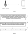
- FIG. 1 is a schematic diagram of a communication system according to an embodiment of the invention.
- the communication system may include, but is not limited to, one network device and one terminal.
- the number and form of devices shown in FIG. 1 are only for illustrative purposes and do not constitute a limitation on the embodiments of the invention, and two or more network devices and two or more terminals may be included in practical applications.
- the communication system shown in FIG. 1 includes, for example, one network device 11 and one terminal 12.
- LTE long term evolution
- 5G 5th generation
- NR 5G new radio
- the network device 11 in the embodiments of the invention is an entity on a network side for transmitting or receiving signals.
- the network device 11 may be an evolved NodeB (eNB), a transmission reception point (TRP), a next generation NodeB (gNB) in a NR system, a base station in other future mobile communication systems, or an access point in a wireless fidelity (WiFi) system.
- eNB evolved NodeB
- TRP transmission reception point
- gNB next generation NodeB
- WiFi wireless fidelity
- the specific technology and specific device form adopted by the network device are not limited in the embodiments of the invention.
- the network device provided by the embodiments of the invention may consist of a central unit (CU) and a distributed unit (DU).
- the CU may also be called a control unit.
- CU-DU structure allows a protocol layer of the network device, such as a base station, to be split, some functions of the protocol layer are placed in the CU for centralized control, and some or all of the remaining functions of the protocol layer are distributed in the DU, which is intensively controlled by the CU.
- the terminal 12 in the embodiments of the invention is an entity on a user side for receiving or transmitting signals, such as a cellular phone.
- the terminal may also be referred to as a terminal, a user equipment (UE), a mobile station (MS), a mobile terminal (MT), and the like.
- the terminal can be a car with communication functions, a smart car, a mobile phone, a wearable device, a Pad, a computer with wireless transceiver functions, a virtual reality (VR) terminal, an augmented reality (AR) terminal, a wireless terminal in industrial control, a wireless terminal in self-driving, a wireless terminal in remote medical surgery, a wireless terminal in smart grid, a wireless terminal in transportation safety, a wireless terminal in smart city, a wireless terminal in smart home, etc.
- the specific technology and specific device form adopted by the terminal are not limited in the embodiments of the invention.
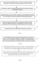
- FIG. 2 is a flowchart of a method for determining SRS resource configuration information according to an embodiment of the invention. The method is performed by a network device. As illustrated in FIG. 2 , the method includes, but is not limited to, the following steps.
- an antenna switching configuration corresponding to a terminal includes 6 transmitting chains and 8 receiving chains and/or 8 transmitting chains and 8 receiving chains, in which the terminal has 8 transmitting antenna ports.
- the network device may first determine the antenna switching configuration on the terminal side when determining an SRS resource configuration corresponding to the terminal.
- a terminal usually has 8 receiving antenna ports.
- the corresponding antenna switching configuration of the terminal includes at least one of 6 transmitting chains or 8 receiving chains, hereinafter referred to as 6T8R, and 8 transmitting chains and 8 receiving chains, hereinafter referred to as 8T8R.
- SRS resource configuration information corresponding to the terminal is determined according to the antenna switching configuration.
- the network device determines the corresponding SRS resource configuration information according to the specific antenna configuration on the terminal side.
- the transmitting antenna ports and the receiving antennas are connected through a switching network. That is, the terminal includes 8 transmitting antenna ports and 8 receiving antenna ports.
- the network device may configure, for the terminal, the SRS resource configuration information including at most one non-periodic SRS resource set.
- the non-periodic SRS resource set includes one SRS resource, and the one SRS resource includes 8 SRS antenna ports.
- the network device may configure, for the terminal, the SRS resource configuration information including at most two SRS resource sets.
- the SRS resource set is a periodic SRS resource set or a semi-persistent SRS resource set. That is, the SRS resource configuration information may at most include two periodic SRS resource sets, or two semi-persistent SRS resource sets, or one periodic SRS resource set and one semi-persistent SRS resource set.
- Each SRS resource set includes one SRS resource, and the one SRS resource includes 8 SRS antenna ports.
- the SRS resource configuration information includes at most two semi-persistent SRS resource sets
- only one semi-persistent SRS resource set can be activated at a time, so that the terminal sends the SRS based on the activated semi-persistent SRS resource set.
- the two semi-persistent SRS resource sets may be configured to correspond to different periods respectively, so that the terminal can send the SRS during an activated period of any of the semi-persistent SRS resource sets periodically according to the period of the activated semi-persistent SRS resource set.
- the network device may also determine, according to whether or not the terminal supports reporting a capability of this feature, to configure, for the terminal, the corresponding SRS resource configuration information including at most three SRS resource sets.
- the SRS resource sets are periodic SRS resource sets or include at most two semi-persistent SRS resource sets. For example, one periodic SRS resource set and two semi-persistent SRS resource sets are configured. Each SRS resource set includes one SRS resource, and the one SRS resource includes 8 antenna ports. If two semi-persistent SRS resource sets are configured, only one SRS resource set needs to be activated at a time.
- the two semi-persistent SRS resource sets may correspond to different periods respectively, so that the terminal can send the SRS during an activated period of any of the semi-persistent SRS resource sets periodically according to the period of the activated semi-persistent SRS resource set.
- the capability of the terminal may be reported by the terminal to the network device or may be determined by the network device according to relevant information reported by the terminal, which is not limited in this invention.
- the SRS resource configuration information is sent to the terminal.
- the network device may send the SRS resource configuration information to the terminal via a radio resource control (RRC) message or via other messages, which is not limited in the invention.
- RRC radio resource control
- the terminal can send the SRS according to the SRS resource configuration information corresponding to the switched antenna configuration and sent by the network device, so that the network device can perform uplink channel measurement according to the received SRS and determine downlink channel information through channel reciprocity.
- the network device may first determine that the antenna switching configuration corresponding to the terminal includes 6T8R and/or 8T8R, and then determine the SRS resource configuration information corresponding to the terminal according to the antenna switching configuration and send the SRS resource configuration information to the terminal. Therefore, the network device configures the SRS resource configuration information corresponding to the antenna switching configuration of 6T8R and/or 8T8R for the terminal with 8 transmitting antenna ports, to provide a condition for supporting the terminal to realize uplink transmission using a maximum number of 8 antenna ports, thereby improving the uplink transmission rate.
- FIG. 4 is a flowchart of a method for determining SRS resource configuration information according to an embodiment of the invention. The method is performed by a network device. As illustrated in FIG. 4 , the method includes, but is not limited to, the following steps.
- indication information sent by a terminal is received, in which the indication information is used to indicate antenna port information of the terminal.
- a number of transmitting antenna ports of the terminal is determined according to the indication information.
- the network device may receive the above indication information via an RRC message or a random access message, which is not limited in the invention.
- the indication information may include a number of antenna ports on the terminal side, or any other information that indicates the number of antenna ports on the terminal side, e.g., antenna structure information, which is not limited in the invention.
- the indication information may include any of the following: a maximum number of supported SRS resource sets, a supported antenna switching configuration or a combination of supported antenna switching configurations, an antenna structure type indicator, or a supported SRS resource configuration identifier.
- the network device may determine that the number of transmitting antenna ports on the terminal side is 8.
- the network device may determine that the number of transmitting antenna ports on the terminal side is 8.
- the antenna structure type indicator may be any identifier that can be used to represent the antenna structure type, based on which the network device can determine the antenna structure type of the terminal.
- the antenna structure type indicator may be a combination of values of n and m in the antenna configuration of nTmR, so that the network device determines the antenna structure type of the terminal according to the combination of values of n and m.
- the terminal may also directly identify its corresponding antenna port information by indicating the supported SRS resource configuration identifier.
- an antenna switching configuration corresponding to the terminal includes 6 transmitting chains and 8 receiving chains and/or 8 transmitting chains and 8 receiving chains, in which the terminal has 8 transmitting antenna ports.
- SRS resource configuration information corresponding to the terminal is determined according to the antenna switching configuration.
- the SRS resource configuration information is sent to the terminal.
- the network device may determine that the SRS resource configuration information corresponding to the terminal includes at most two SRS resource sets. That is, the network device may configure at most two periodic SRS resource sets, or two semi-persistent SRS resource sets, or one periodic SRS resource set and one semi-persistent SRS resource set, for the terminal.
- the network device may also determine that the SRS resource configuration information corresponding to the terminal includes at most three SRS resource sets according to the capability of the terminal, for example, a maximum number of SRS resource sets supported by the terminal being 3.
- the SRS resource set is a periodic SRS resource set or a semi-persistent resource set. For example, one periodic SRS resource set and two semi-persistent SRS resource sets are configured for the terminal. If two semi-persistent SRS resource sets are configured, only one SRS resource set needs to be activated at a time.
- the two semi-persistent SRS resource sets correspond to different periods, so that the terminal can send the SRS during an activated period of any of the semi-persistent SRS resource sets periodically according to the period of the activated semi-persistent SRS resource set.
- each SRS resource set or SRS resource is configured can be determined according to the antenna implementation structure on the terminal side.
- the network device may determine that each periodic SRS resource set or each semi-persistent SRS resource set includes 3 SRS resources, in which one SRS resource includes 4 antenna ports, and each of the other two SRS resources includes 2 antenna ports. That is, the corresponding SRS resource configuration information is shown in Table 1.
- Table 1 Transmitting antenna port ⁇ SRS resource #1 #2 #3 Tx0 AP0 Tx1 AP1 Tx2 AP2 Tx3 AP3 Tx4 AP4 AP6 Tx5 AP5 AP7
- guard interval there may or may not be a guard interval between resource #1 and resource #2 or resource #3, which is not limited in the invention. Since the terminal needs to switch the receiving antennas in the antenna switching configuration corresponding to resource #2 and resource #3, which requires a certain amount of time for switching, a guard interval is required between resource #2 and resource #3, and the terminal does not send the SRS during the guard interval.
- the guard interval may be 1 symbol or several symbols, which is not limited in the invention.
- the network device may configure an SRS resource set including 2 SRS resources, in which each SRS resource includes 4 antenna ports.
- the corresponding SRS resource configuration information may be as shown in Table 2.
- Table 2 Transmitting antenna port ⁇ SRS resource #1 #2 Tx0 AP0 Tx1 AP1 Tx2 AP2 AP4 Tx3 AP3 AP5 Tx4 AP6 Tx5 AP7
- the terminal needs to switch the receiving antennas in the antenna switching configuration corresponding to resource #1 and resource #2, which requires a certain amount of time for switching, a guard interval is required between resource #1 and resource #2, and the terminal does not send the SRS during the guard interval.
- the guard interval may be 1 symbol or several symbols, which is not limited in the invention.
- the network device may configure one SRS resource set including 4 SRS resources, in which each SRS resource includes 2 antenna ports.
- the SRS resource configuration information may be as shown in Table 3.
- Table 3 Transmitting antenna port ⁇ SRS resource #1 #2 #3 #4 Tx0 AP0 Tx1 AP1 Tx2 AP2 Tx3 AP3 Tx4 AP4 AP6 Tx5 AP5 AP7
- the transmitting antenna ports sounding may be performed for more than one time.
- the guard interval may be 1 symbol or several symbols, which is not limited in the invention.
- the network device may configure one SRS resource set including 4 SRS resources, in which each SRS resource includes 4 antenna ports.
- the SRS resource configuration information may be as shown in Table 4.
- Table 4 Transmitting antenna port ⁇ SRS resource #1 #2 #3 #4 Tx0 AP0 AP0 Tx1 AP1 AP1 Tx2 AP2 AP4 AP2 Tx3 AP3 AP5 AP3 Tx4 AP6 AP6 AP4 Tx5 AP7 AP7 AP5
- the terminal needs to switch antennas in the antenna switching configuration corresponding to each resource, which requires a certain amount of time for switching, a guard interval is required between any two of the resources, and the terminal does not send the SRS during the guard interval.
- the guard interval may be 1 symbol or several symbols, which is not limited in the invention.
- the network device after receiving the indication information sent by the terminal, the network device first determines the number of transmitting antenna ports in the terminal, and for the terminal with 8 transmitting antenna ports, configures the SRS resource configuration information corresponding to the antenna switching configuration of 6T8R and/or 8T8R, to provide a condition for supporting the terminal to realize uplink transmission using a maximum number of 8 antenna ports, thereby improving the uplink transmission rate.
- FIG. 7 is a flowchart of a method for determining SRS resource configuration information according to an embodiment of the invention. The method is performed by a network device. As illustrated in FIG. 7 , the method includes, but is not limited to, the following steps.
- step 701 indication information sent by a terminal is received, in which the indication information is used to indicate antenna port information of the terminal.
- a number of transmitting antenna ports of the terminal is determined according to the indication information.
- an antenna switching configuration corresponding to the terminal includes 6 transmitting chains and 8 receiving chains and/or 8 transmitting chains and 8 receiving chains, in which the terminal has 8 transmitting antenna ports.
- a non-periodic SRS resource configuration included in SRS resource configuration information corresponding to the antenna switching configuration of 6T8R is determined according to an antenna structure type of the terminal.
- the non-periodic SRS resource configuration includes at most 3 non-periodic SRS resource sets.
- the first type of antenna structure is shown in FIG. 5 .
- the corresponding non-periodic SRS resource may be as shown in Table 1. That is, the number of non-periodic SRS resources included in the non-periodic SRS resource configuration is 3, in which one non-periodic SRS resource includes 4 antenna ports, and each of the other two non-periodic SRS resources includes 2 antenna ports.
- the three SRS resources in Table 1 may be located in a single non-periodic SRS resource set, or may be located in different non-periodic SRS resource sets, which is not limited in the invention.
- the non-periodic SRS resource configuration includes at most two non-periodic SRS resource sets.
- the second type of antenna structure is shown in FIG. 6 .
- the corresponding non-periodic SRS resource may be as shown in Table 2. That is, the number of non-periodic SRS resources included in the non-periodic SRS resource configuration is 2, in which each non-periodic SRS resource includes 4 antenna ports, and there is a guard interval between the two non-periodic SRS resources.
- the 2 SRS resources in Table 2 may be located in a single non-periodic SRS resource set, or may be located in different non-periodic SRS resource sets, which is not limited in the invention.
- the non-periodic SRS resource configuration includes at most 4 non-periodic SRS resource sets.
- the second type of antenna structure is shown in FIG. 6 .
- the corresponding non-periodic SRS resource may be as shown in Table 3. That is, the number of non-periodic SRS resources included in the non-periodic SRS resource configuration is 4, in which each non-periodic SRS resource includes 2 antenna ports, and there is a guard interval between at least two non-periodic SRS resources.
- the 4 SRS resources in Table 3 may be located in a single non-periodic SRS resource set, or may be located in different non-periodic SRS resource sets, which is not limited in the invention.
- the non-periodic SRS resource configuration includes at most 4 non-periodic SRS resource sets.
- the second type of antenna structure is shown in FIG. 6 .
- the corresponding non-periodic SRS resource may be as shown in Table 4. That is, the number of non-periodic SRS resources included in the non-periodic SRS resource configuration is 4, in which each non-periodic SRS resource includes 4 antenna ports, and there is a guard interval between every two non-periodic SRS resources.
- the 4 SRS resources in Table 4 may be located in a single non-periodic SRS resource set, or may be located in different non-periodic SRS resource sets, which is not limited in the invention.
- the network device may determine the guard interval between the non-periodic SRS resource sets according to a protocol. For example, if the protocol specifies that there is no guard interval between the non-periodic SRS resource sets, the network device may not set any guard interval. Alternatively, if the protocol specifies that a symbol is set between the non-periodic SRS resource sets as a guard interval, the network device may set the guard interval between the non-periodic SRS resource sets to be 1 symbol, which is not limited in the invention.
- the network device may determine the guard interval between the non-periodic SRS resource sets according to a configuration of the network device. That is, when the network device allocates resources, it ensures that the allocated resources leave enough time for the terminal to switch antennas. In this case, there may or may not be a guard interval between the non-periodic SRS resource sets, which is not limited in the invention.
- the network device may determine the guard interval between the non-periodic SRS resources according to a protocol, or determine the guard interval between the non-periodic SRS resources according to a configuration of the network device.
- the guard interval between the non-periodic SRS resources may be determined according to the capability of the terminal.
- the network device can also configure different guard intervals according to different antenna switching implementations of the terminal.
- the terminal needs to report its own antenna switching implementation capability for configuration, and the network device configures the specific guard interval according to the specific capability of the terminal.
- the SRS resource configuration information is sent to the terminal.
- the network device after receiving the indication information sent by the terminal, the network device first determines the number of transmitting antenna ports in the terminal, and for the terminal with 8 transmitting antenna ports, determines the non-periodic SRS resource configuration included in the SRS resource configuration information corresponding to the antenna switching configuration of 6T8R according to the antenna structure type of the terminal, to provide a condition for supporting the terminal to realize uplink transmission using a maximum number of 8 antenna ports, thereby improving the uplink transmission rate.
- FIG. 8 is a flowchart of a method for determining SRS resource configuration information according to an embodiment of the invention. The method is performed by a terminal. As illustrated in FIG. 8 , the method includes, but is not limited to, the following steps.
- SRS resource configuration information sent by a network device is received, in which an antenna switching configuration corresponding to the SRS resource configuration information includes 6 transmitting chains and 8 receiving chains and/or 8 transmitting chains and 8 receiving chains.
- the terminal has 8 receiving antenna ports.
- the network device determines that the corresponding antenna switching configuration of the terminal includes at least one of 6T8R or 8T8R, and determines its corresponding SRS resource configuration information according to the antenna switching configuration.
- the transmitting antenna ports and the receiving antennas are connected through a switching network. That is, the terminal includes 8 transmitting antenna ports and 8 receiving antenna ports.
- the antenna switching configuration corresponding to the terminal is 8T8R
- the SRS resource configuration information may include at most one non-periodic SRS resource set.
- the non-periodic SRS resource set includes one SRS resource, and the one SRS resource includes 8 SRS antenna ports.
- the antenna switching configuration corresponding to the terminal is 8T8R
- the SRS resource configuration information includes at most two SRS resource sets, in which the SRS resource set is a periodic SRS resource set or a semi-persistent SRS resource set. That is, the SRS resource configuration information may include at most two periodic SRS resource sets, or two semi-persistent SRS resource sets, or one periodic SRS resource set and one semi-persistent SRS resource set.
- One SRS resource set includes one SRS resource, and the one SRS resource includes 8 SRS antenna ports.
- the SRS resource configuration information includes at most two semi-persistent SRS resource sets
- only one semi-persistent SRS resource set can be activated at a time, so that the terminal sends the SRS based on the activated semi-persistent SRS resource set.
- the two semi-persistent SRS resource sets may correspond to different periods respectively, so that the terminal can send the SRS during an activated period of any of the semi-persistent SRS resource sets periodically according to the period of the activated semi-persistent SRS resource set.
- the antenna switching configuration corresponding to the terminal is 8T8R
- the maximum number of SRS resource sets supported by the terminal is 3
- the SRS resource configuration information includes at most three periodic SRS resource sets.
- the SRS resource set is a periodic SRS resource set or a semi-persistent SRS resource set. For example, one periodic SRS resource set and two semi-persistent SRS resource sets are configured.
- One SRS resource set includes one SRS resource, and the one SRS resource includes 8 antenna ports. If two semi-persistent SRS resource sets are configured, only one SRS resource set needs to be activated at a time.
- the two semi-persistent SRS resource sets may be configured with different periods respectively, so that the terminal can send the SRS during an activated period of any of the semi-persistent SRS resource sets periodically according to the period of the activated semi-persistent SRS resource set.
- the capability of the terminal may be reported by the terminal to the network device or may be determined by the network device according to relevant information reported by the terminal, which is not limited in this invention.
- the network device may send the SRS resource configuration information to the terminal via a radio resource control (RRC) message or via other messages, which is not limited in the invention.
- RRC radio resource control
- the terminal can send the SRS according to the SRS resource configuration information corresponding to the switched antenna configuration and sent by the network device, so that the network device can perform uplink channel measurement according to the received SRS and determine downlink channel information through channel reciprocity.
- the network device may configure the corresponding SRS resource configuration information for the terminal whose antenna switching configuration includes 6T8R and/or 8T8R, so that the terminal may realize uplink transmission using a maximum number of 8 antenna ports, thereby improving the uplink transmission rate.
- FIG. 9 is a flowchart of a method for determining SRS resource configuration information according to an embodiment of the invention. The method is performed by a terminal. As illustrated in FIG. 9 , the method includes, but is not limited to, the following steps.
- indication information is sent to a network device, in which the indication information is used to indicate antenna port information of the terminal.
- the terminal may send the above indication information via an RRC message or a random access message, which is not limited in the invention.
- the indication information may include a number of antenna ports on the terminal side, or any other information that indicates the number of antenna ports on the terminal side, e.g., antenna structure information, which is not limited in the invention.
- the indication information may include any of the following: a maximum number of supported SRS resource sets, a supported antenna switching configuration or a combination of supported antenna switching configurations, an antenna structure type indicator, or a supported SRS resource configuration identifier.
- the network device may determine that the number of transmitting antenna ports on the terminal side is 8.
- the network device may determine that the number of transmitting antenna ports on the terminal side is 8.
- the antenna structure type indicator may be any identifier that can be used to represent the antenna structure type, based on which the network device can determine the antenna structure type of the terminal.
- the antenna structure type indicator may be a combination of values of n and m in the antenna configuration of nTmR, so that the network device determines the antenna structure type of the terminal according to the combination of values of n and m.
- the terminal may also directly identify its corresponding antenna port information by indicating the supported SRS resource configuration identifier.
- SRS resource configuration information sent by the network device is received, in which an antenna switching configuration corresponding to the SRS resource configuration information includes 6T8R and/or 8T8R.
- the SRS resource configuration information configured by the network device includes at most two SRS resource sets, in which the SRS resource set is a periodic SRS resource set or a semi-persistent SRS resource set. That is, the network device may configure at most two periodic SRS resource sets, or two semi-persistent SRS resource sets, or one periodic SRS resource set and one semi-persistent SRS resource set, for the terminal.
- the antenna switching configuration corresponding to the terminal includes the configuration of 6T8R, the maximum number of SRS resource sets supported by the terminal is 3, and the SRS resource configuration information includes at most three SRS resource sets, in which the SRS resource set is a periodic SRS resource set or a semi-persistent SRS resource set. For example, one periodic SRS resource set and at most two semi-persistent SRS resource sets are configured. If two semi-persistent SRS resource sets are configured, only one SRS resource set needs to be activated at a time.
- the two semi-persistent SRS resource sets correspond to different periods, so that the terminal can send the SRS during an activated period of any of the semi-persistent SRS resource sets periodically according to the period of the activated semi-persistent SRS resource set.
- the SRS resource configuration information may also be related to the antenna implementation structure on the terminal side.
- one SRS resource set may include 3 SRS resources, in which one SRS resource includes 4 antenna ports, and each of the other two SRS resources includes 2 antenna ports. That is, the corresponding SRS resource configuration information is shown in Table 1.
- one SRS resource set may include 2 SRS resources, in which one SRS resource includes 4 antenna ports.
- the corresponding SRS resource configuration information may be as shown in Table 2 above.
- the network device may also configure one SRS resource set including 4 SRS resources, in which one SRS resource includes 2 antenna ports.
- the SRS resource configuration information may be as shown in Table 3 above.
- the network device may also configure one SRS resource set including 4 SRS resources, in which one SRS resource includes 4 antenna ports.
- the SRS resource configuration information can be shown in Table 4.
- the non-periodic SRS resource configuration includes at most three non-periodic SRS resource sets.
- the corresponding non-periodic SRS resource may be as shown in Table 1. That is, the number of non-periodic SRS resources included in the non-periodic SRS resource configuration is 3, in which one non-periodic SRS resource includes 4 antenna ports, and each of the other two non-periodic SRS resources includes 2 antenna ports.
- the three SRS resources in Table 1 may be located in a single non-periodic SRS resource set, or may be located in different non-periodic SRS resource sets, which is not limited in the invention.
- the antenna structure type of the terminal is a second type
- the non-periodic SRS resource configuration includes at most two non-periodic SRS resource sets, in which the antenna switching configuration corresponding to the terminal is 6T8R.
- the second type of antenna structure is shown in FIG. 6 .
- the corresponding non-periodic SRS resource may be as shown in Table 2. That is, the number of non-periodic SRS resources included in the non-periodic SRS resource configuration is 2, in which each non-periodic SRS resource includes 4 antenna ports, and there is a guard interval between the two non-periodic SRS resources.
- the 2 SRS resources in Table 2 may be located in a single non-periodic SRS resource set, or may be located in different non-periodic SRS resource sets, which is not limited in the invention.
- the antenna structure type of the terminal is a second type
- the non-periodic SRS resource configuration includes at most four non-periodic SRS resource sets, in which the antenna switching configuration corresponding to the terminal is 6T8R.
- the second type of antenna structure is shown in FIG. 6 .
- the corresponding non-periodic SRS resource may be as shown in Table 3. That is, the number of non-periodic SRS resources included in the non-periodic SRS resource configuration is 4, in which each non-periodic SRS resource includes 2 antenna ports, and there is a guard interval between at least two non-periodic SRS resources.
- the 4 SRS resources in Table 3 may be located in a single non-periodic SRS resource set, or may be located in different non-periodic SRS resource sets, which is not limited in the invention.
- the non-periodic SRS resource configuration includes at most four non-periodic SRS resource sets, in which the antenna switching configuration corresponding to the terminal is 6T8R.
- the second type of antenna structure is shown in FIG. 6 .
- the corresponding non-periodic SRS resource may be as shown in Table 4. That is, the number of non-periodic SRS resources included in the non-periodic SRS resource configuration is 4, in which each non-periodic SRS resource includes 4 antenna ports, and there is a guard interval between every two non-periodic SRS resources.
- the 4 SRS resources in Table 4 may be located in a single non-periodic SRS resource set, or may be located in different non-periodic SRS resource sets, which is not limited in the invention.
- guard interval there may or may not be a guard interval between the above non-periodic SRS resource sets.
- the size of the guard interval and whether the guard interval needs to be included may be determined by the network device according to a protocol, or may be determined by the network device to ensure that the allocated resources leave enough time for the terminal to switch antennas, which is not limited in the invention.
- the non-periodic SRS resources may be determined by the network device according to a protocol, or according to a configuration of the network device, or according to a capability of the terminal, which is not limited in the invention.
- the terminal configured with 8 transmitting ports first reports its own antenna port information to the network device, and then receives the corresponding SRS resource configuration information configured by the network device, so that the terminal can realize uplink transmission using a maximum of 8 antenna ports, thereby improving the uplink transmission rate.
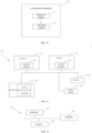
- FIG. 10 is a schematic diagram of a communication apparatus 100 according to an embodiment of the invention.
- the communication apparatus 100 shown in FIG. 10 may include a transceiver module 101 and a processing module 102.
- the transceiver module 101 may include a transmitting module and/or a receiving module.
- the transmitting module is used for realizing a transmitting function
- the receiving module is used for realizing a receiving function.
- the transceiver module 101 may realize the transmitting function and/or the receiving function.
- the communication apparatus 100 may be a network device, an apparatus in the network device, or an apparatus capable of being used in combination with the network device.
- the communication apparatus 100 is located on the network device side.
- the processing module 102 is configured to determine that an antenna switching configuration corresponding to a terminal comprises 6 transmitting chains and 8 receiving chains and/or 8 transmitting chains and 8 receiving chains, and to determine SRS resource configuration information corresponding to the terminal according to the antenna switching configuration, in which the terminal has 8 transmitting antenna ports.
- the transceiver module 101 is configured to send the SRS resource configuration information to the terminal.
- processing module 102 is configured to:
- one SRS resource set includes one SRS resource, and one SRS resource includes 8 antenna ports.
- processing module 102 is configured to:
- one SRS resource set includes 2 SRS resources, and one SRS resource includes 4 antenna ports; or
- the processing module 102 is configured to: determine a non-periodic SRS resource configuration included in the SRS resource configuration information according to an antenna structure type of the terminal, in which the antenna switching configuration of the terminal is 6T8R.
- processing module 102 is configured to:
- processing module 102 is configured to:
- processing module 102 is configured to:
- processing module 102 is configured to:
- the transceiver module 101 is configured to: receive indication information sent by the terminal, in which the indication information is used to indicate antenna port information of the terminal.
- the processing module 102 is configured to: determine a number of transmitting antenna ports of the terminal according to the indication information.
- the indication information includes at least one of the following:
- the communication apparatus 100 may be a terminal, an apparatus in the terminal, or an apparatus capable of being used in combination with the terminal.
- the communication apparatus 100 is provided on the terminal side.
- the transceiver module 101 is configured to receive SRS resource configuration information sent by a network device, in which an antenna switching configuration corresponding to the SRS resource configuration information includes 6 transmitting chains and 8 receiving chains and/or 8 transmitting chains and 8 receiving chains.
- the SRS resource configuration information includes at most one non-periodic SRS resource set; or
- one SRS resource set includes one SRS resource, and one SRS resource includes 8 antenna ports.
- the SRS resource configuration information includes at most two SRS resource sets, in which an SRS resource set is a periodic SRS resource set or a semi-persistent SRS resource set; or a maximum number of SRS resource sets supported by the terminal is 3, and the SRS resource configuration information includes at most three SRS resource sets, in which an SRS resource set is a periodic SRS resource set or a semi-persistent SRS resource set, and the antenna switching configuration corresponding to the terminal is 6T8R.
- one SRS resource set includes 2 SRS resources, and one SRS resource includes 4 antenna ports; or
- the antenna structure type of the communication apparatus is a first type, and the non-periodic SRS resource configuration includes at most three non-periodic SRS resource sets;
- the antenna structure type of the communication apparatus is a first type
- the SRS resource configuration information includes three non-periodic SRS resources, in which one non-periodic SRS resource includes 4 antenna ports, and each of the other two non-periodic SRS resources includes 2 antenna ports; or
- the transceiver module 101 is configured to: send indication information to the network device, in which the indication information is used to indicate antenna port information of the terminal.
- the indication information includes at least one of the following:
- the network device configures the SRS resource configuration information corresponding to the antenna switching configuration of 6T8R and/or 8T8R for the communication apparatus with 8 transmitting antenna ports, to provide a condition for supporting the communication apparatus to realize uplink transmission using a maximum number of 8 antenna ports, thereby improving the uplink transmission rate.
- FIG. 11 is a schematic diagram of a communication apparatus according to an embodiment of the invention.
- the communication apparatus 110 may be a network device, a terminal, or a chip, a chip system or a processor that supports the network device to realize the above-described methods, or a chip, a chip system or a processor that supports the terminal to realize the above-described methods.
- the apparatus may be used to realize the methods described in the above method embodiments with reference to the description of the above-described method embodiments.
- the communication apparatus 110 may include one or more processors 1101.
- the processor 1101 may be a general purpose processor or a dedicated processor, such as, a baseband processor or a central processor.
- the baseband processor is used for processing communication protocols and communication data.
- the central processor is used for controlling the communication apparatus (e.g., base station, baseband chip, terminal, terminal chip, DU, or CU), executing computer programs, and processing data of the computer programs.
- the communication apparatus 110 may include one or more memories 1102 on which computer programs 1104 may be stored.
- the processor 1101 executes the computer programs 1104 to cause the communication apparatus 110 to perform the methods described in the above method embodiments.
- the memory 1102 may also store data.
- the communication apparatus 110 and the memory 1102 can be provided separately or integrated together.
- the communication apparatus 110 may also include a transceiver 1105 and an antenna 1106.
- the transceiver 1105 may be referred to as transceiver unit, transceiver machine, or transceiver circuit, for realizing the transceiver function.
- the transceiver 1105 may include a receiver and a transmitter.
- the receiver may be referred to as receiver machine or receiving circuit, for realizing the receiving function.
- the transmitter may be referred to as transmitter machine or transmitting circuit, for realizing the transmitting function.
- the communication apparatus 110 may also include one or more interface circuits 1107.
- the interface circuits 1107 are used to receive code instructions and transmit them to the processor 1101.
- the processor 1101 runs the code instructions to cause the communication apparatus 110 to perform the method described in the method embodiments.
- the processor 1101 is used to perform steps 201-202 in FIG. 2 , steps 402-404 in FIG. 4 , and steps 702-704 in FIG. 7 .
- the transceiver 1105 is used to perform step 801 in FIG. 8 , and steps 901-902 in FIG. 9 .
- the processor 1101 may include a transceiver for implementing the receiving and transmitting functions.
- the transceiver may be, for example, a transceiver circuit, an interface, or an interface circuit.
- the transceiver circuit, interface, or interface circuit for implementing the receiving and transmitting functions may be separated or integrated together.
- the transceiver circuit, interface, or interface circuit described above may be used for code/data reading and writing, or may be used for signal transmission or delivery.
- the processor 1101 may store computer programs 1103.
- the communication apparatus 110 is caused to perform the methods described in the method embodiments above.
- the computer programs 1103 may be solidified in the processor 1101, in which case the processor 1101 may be implemented by hardware.
- the communication apparatus 110 may include circuits.
- the circuits may implement the sending, receiving or communicating function in the preceding method embodiments.
- the processor and transceiver described in this invention may be implemented on integrated circuits (ICs), analog ICs, radio frequency integrated circuits (RFICs), mixed signal ICs, application specific integrated circuits (ASICs), printed circuit boards (PCBs), and electronic devices.
- ICs integrated circuits
- RFICs radio frequency integrated circuits
- ASICs application specific integrated circuits
- PCBs printed circuit boards
- the processor and transceiver may also be produced using various IC process technologies, such as complementary metal oxide semiconductor (CMOS), nMetal-oxide-semiconductor (NMOS), positive channel metal oxide semiconductor (PMOS), bipolar junction transistor (BJT), bipolar CMOS (BiCMOS), silicon-germanium (SiGe), gallium arsenide (GaAs) and so on.
- CMOS complementary metal oxide semiconductor
- NMOS nMetal-oxide-semiconductor
- PMOS positive channel metal oxide semiconductor
- BJT bipolar junction transistor
- BiCMOS bipolar CMOS
- SiGe silicon-germanium
- GaAs gallium arsenide
- the communication apparatus in the above description of embodiments may be a network device or an access network device (e.g., the terminal in the above method embodiments), but the scope of the communication apparatus described in the invention is not limited thereto, and the structure of the communication apparatus may not be limited by FIG. 11 .
- the communication apparatus may be a stand-alone device or may be part of a larger device.
- the described communication apparatus may be:
- the communication apparatus may be a chip or chip system may be referred to the schematic diagram of a chip shown in FIG. 12 .
- the chip includes a processor 1201 and an interface 1203. There may be one or more processors 1201, and there may be multiple interfaces 1203.
- the interface 1203 is used to implement step 203 in FIG. 2 , steps 401 and 405 in FIG. 4 , and steps 701 and 705 in FIG. 7 .
- the interface 1203 is used to implement step 801 in FIG. 8 , and steps 901-902 in FIG. 9 .
- the chip further includes a memory 1202 used for storing necessary computer programs and data.
- the invention also provides a readable storage medium having instructions stored thereon. When the instructions are executed by a computer, the function of any of the method embodiments described above is implemented.
- the invention also provides a computer program product.
- the computer program product is executed by a computer, the function of any of the method embodiments described above is implemented.
- the above embodiments may be implemented in whole or in part by software, hardware, firmware, or any combination thereof.
- software When implemented using software, it may be implemented, in whole or in part, in the form of a computer program product.
- the computer program product includes one or more computer programs. When loading and executing the computer program on the computer, all or part of processes or functions described in the embodiments of the invention may be implemented.
- the computer may be a general-purpose computer, a dedicated computer, a computer network, or other programmable devices.
- the computer program may be stored in a computer-readable storage medium or transmitted from one computer-readable storage medium to another computer-readable storage medium.
- the computer program may be transmitted from one web site, computer, server, or data center to another web site, computer, server, or data center, in a wired manner (e.g., by using coaxial cables, fiber optics, or digital subscriber lines (DSLs) or wirelessly (e.g., by using infrared wave, wireless wave, or microwave).
- the computer-readable storage medium may be any usable medium to which the computer has access or a data storage device such as a server and a data center integrated by one or more usable mediums.
- the usable medium may be a magnetic medium (e.g., floppy disk, hard disk, and tape), an optical medium (e.g., a high-density digital video disc (DVD)), or a semiconductor medium (e.g., a solid state disk (SSD)).
- a magnetic medium e.g., floppy disk, hard disk, and tape
- an optical medium e.g., a high-density digital video disc (DVD)
- DVD high-density digital video disc
- SSD solid state disk
- the term “multiple” in the invention refers to two or more, which is the similar for other quantifiers.
- the term “and/or” describes a relation of associated objects, which indicates three relations, for example, "A and/or B” indicates that A exists alone, A and B both exist, and B exists alone.
- the character “/” generally indicates that the associated objects prior to and after the character "/” is an “or” relation.
- the terms “a”, “said” and “the” in the singular form are also intended to include the plural form, unless the context clearly indicates otherwise.
- the term “at least one” in the invention may also be described as one or more, and the term “multiple” may be two, three, four, or more, which is not limited in the invention.
- “first”, “second”, and “third”, and “A”, “B”, “C” and “D” are used to distinguish different technical features of the type, the technical features described using the “first”, “second”, and “third”, and “A”, “B”, “C” and “D” do not indicate any order of precedence or magnitude.
- the correspondences shown in the tables in this invention may be configured or predefined.
- the values of information in the tables are merely examples and may be configured to other values, which are not limited by the invention.
- the correspondences illustrated in certain rows in the tables in this invention may not be configured.
- the above tables may be adjusted appropriately, such as splitting, combining, and the like.
- the names of the parameters shown in the titles of the above tables may be other names that may be understood by the communication apparatus, and the values or representations of the parameters may be other values or representations that may be understood by the communication apparatus.
- Each of the above tables may also be implemented with other data structures, such as, arrays, queues, containers, stacks, linear tables, pointers, chained lists, trees, graphs, structures, classes, heaps, and Hash tables.
- predefine in this invention may be understood as define, define in advance, store, pre-store, pre-negotiate, pre-configure, solidify, or pre-fire.
Landscapes
- Engineering & Computer Science (AREA)
- Signal Processing (AREA)
- Computer Networks & Wireless Communication (AREA)
- Mobile Radio Communication Systems (AREA)
Applications Claiming Priority (1)
| Application Number | Priority Date | Filing Date | Title |
|---|---|---|---|
| PCT/CN2022/079609 WO2023168576A1 (zh) | 2022-03-07 | 2022-03-07 | 确定探测参考信号srs资源配置信息的方法及其装置 |
Publications (2)
| Publication Number | Publication Date |
|---|---|
| EP4492889A1 true EP4492889A1 (de) | 2025-01-15 |
| EP4492889A4 EP4492889A4 (de) | 2025-05-07 |
Family
ID=87936950
Family Applications (1)
| Application Number | Title | Priority Date | Filing Date |
|---|---|---|---|
| EP22930222.9A Pending EP4492889A4 (de) | 2022-03-07 | 2022-03-07 | Verfahren zur bestimmung von ressourcenkonfigurationsinformationen eines sounding-referenzsignals (srs) und vorrichtung damit |
Country Status (4)
| Country | Link |
|---|---|
| US (1) | US20250184102A1 (de) |
| EP (1) | EP4492889A4 (de) |
| CN (1) | CN117730597A (de) |
| WO (1) | WO2023168576A1 (de) |
Families Citing this family (3)
| Publication number | Priority date | Publication date | Assignee | Title |
|---|---|---|---|---|
| CN120825209A (zh) * | 2024-04-12 | 2025-10-21 | 华为技术有限公司 | 一种通信方法及装置 |
| CN121603964A (zh) * | 2024-08-20 | 2026-03-03 | 维沃移动通信有限公司 | 传输方法、配置方法、装置、终端及网络侧设备 |
| KR20260031555A (ko) * | 2024-08-29 | 2026-03-09 | 삼성전자주식회사 | 통신 시스템에서 상향링크 송신 안테나 스위칭 방법 및 장치 |
Family Cites Families (8)
| Publication number | Priority date | Publication date | Assignee | Title |
|---|---|---|---|---|
| US11638217B2 (en) * | 2019-10-09 | 2023-04-25 | Qualcomm Incorporated | SRS antenna switching for multiple receive antennas |
| EP4344084B1 (de) * | 2020-02-19 | 2025-06-04 | Guangdong Oppo Mobile Telecommunications Corp., Ltd. | Antennenumschaltverfahren, endgerätevorrichtung und kommunikationsvorrichtung |
| WO2021163937A1 (zh) * | 2020-02-19 | 2021-08-26 | Oppo广东移动通信有限公司 | 天线切换能力指示方法、终端设备及通信设备 |
| US11588560B2 (en) * | 2020-02-21 | 2023-02-21 | Qualcomm Incorporated | Adaptation of transmit and receive antennas |
| CN113300823A (zh) * | 2020-02-21 | 2021-08-24 | 维沃移动通信有限公司 | Srs的传输方法、码本传输方法、装置、终端及介质 |
| CN115039475B (zh) * | 2020-04-11 | 2025-04-01 | 中兴通讯股份有限公司 | 一种用于改进的探测参考信号(srs)开销和灵活重用方案的方法和系统 |
| US20230336304A1 (en) * | 2020-05-15 | 2023-10-19 | Nec Corporation | Method, device and computer readable medium for communication |
| KR20230131337A (ko) * | 2022-03-03 | 2023-09-13 | 삼성전자주식회사 | 네트워크 협력 통신을 위한 상향링크 데이터 반복 송수신 방법 및 장치 |
-
2022
- 2022-03-07 CN CN202280000633.5A patent/CN117730597A/zh active Pending
- 2022-03-07 WO PCT/CN2022/079609 patent/WO2023168576A1/zh not_active Ceased
- 2022-03-07 EP EP22930222.9A patent/EP4492889A4/de active Pending
- 2022-03-07 US US18/844,339 patent/US20250184102A1/en active Pending
Also Published As
| Publication number | Publication date |
|---|---|
| EP4492889A4 (de) | 2025-05-07 |
| CN117730597A (zh) | 2024-03-19 |
| WO2023168576A1 (zh) | 2023-09-14 |
| US20250184102A1 (en) | 2025-06-05 |
Similar Documents
| Publication | Publication Date | Title |
|---|---|---|
| EP4518201A1 (de) | Verfahren und vorrichtung zur bestimmung des konfigurationsanzeigezustands | |
| EP4440176A1 (de) | Strahlanzeigeverfahren für dienstverbindung eines intelligenten repeaters und vorrichtung dafür | |
| EP4376483A1 (de) | Verfahren und vorrichtung zur messmeldung einer relaisendgerätevorrichtung | |
| US20250260543A1 (en) | Method and apparatus for determining transmission configuration indication state | |
| US20250392970A1 (en) | Method and apparatus for reporting beam measurement result | |
| EP4492889A1 (de) | Verfahren zur bestimmung von ressourcenkonfigurationsinformationen eines sounding-referenzsignals (srs) und vorrichtung damit | |
| EP4525534A1 (de) | Ressourcenkonfigurationsverfahren und -vorrichtung | |
| US20250274915A1 (en) | Methods and apparatuses for data transmission | |
| CN114208239B (zh) | 一种新空口和新空口侧行链路切换的方法及装置 | |
| EP4539375A1 (de) | Anzeigeverfahren für den anzeigestatus einer übertragungskonfiguration und vorrichtungen | |
| US20250016579A1 (en) | Beam indication method and device for smart repeater | |
| US20240397308A1 (en) | Resource configuration method, apparatus and storage medium | |
| US20260046009A1 (en) | Sidelink (sl) beam configuration method and apparatus, device and storage medium | |
| US20250227457A1 (en) | Method and device for reporting antenna switching capability | |
| EP4358441A1 (de) | Kommunikationsverfahren und -vorrichtung | |
| US20250080294A1 (en) | Method for triggering sounding reference signal (srs) used for antenna switching and device thereof | |
| EP4518211A1 (de) | Verarbeitungsverfahren für rückkopplung von hybriden automatischen wiederholungsanfragen (harq) und vorrichtung dafür | |
| US20260095361A1 (en) | Information reporting method and apparatus thereof | |
| EP4472308A1 (de) | Funkrufauslöseverfahren und -vorrichtung | |
| EP4408061A1 (de) | Messlückenplanungsverfahren und vorrichtung dafür | |
| US20240405948A1 (en) | Method and apparatus for reporting multi-carrier aggregation capability | |
| US20240292384A1 (en) | Resource allocation method and apparatus thereof | |
| CN114026907A (zh) | 一种上行波束的测量方法及其装置 | |
| EP4601252A1 (de) | Verfahren zur bestimmung der vorbereitungszeit für uplink-antennenschaltung und vorrichtungen | |
| US20260129644A1 (en) | Method for determining preparation time for uplink antenna switching, and apparatuses |
Legal Events
| Date | Code | Title | Description |
|---|---|---|---|
| STAA | Information on the status of an ep patent application or granted ep patent |
Free format text: STATUS: THE INTERNATIONAL PUBLICATION HAS BEEN MADE |
|
| PUAI | Public reference made under article 153(3) epc to a published international application that has entered the european phase |
Free format text: ORIGINAL CODE: 0009012 |
|
| STAA | Information on the status of an ep patent application or granted ep patent |
Free format text: STATUS: REQUEST FOR EXAMINATION WAS MADE |
|
| 17P | Request for examination filed |
Effective date: 20241002 |
|
| AK | Designated contracting states |
Kind code of ref document: A1 Designated state(s): AL AT BE BG CH CY CZ DE DK EE ES FI FR GB GR HR HU IE IS IT LI LT LU LV MC MK MT NL NO PL PT RO RS SE SI SK SM TR |
|
| A4 | Supplementary search report drawn up and despatched |
Effective date: 20250404 |
|
| RIC1 | Information provided on ipc code assigned before grant |
Ipc: H04L 5/00 20060101ALI20250331BHEP Ipc: H04W 72/04 20230101AFI20250331BHEP |
|
| DAV | Request for validation of the european patent (deleted) | ||
| DAX | Request for extension of the european patent (deleted) |