EP4494450A1 - Unité de séparation pour une moissonneuse-batteuse - Google Patents
Unité de séparation pour une moissonneuse-batteuse Download PDFInfo
- Publication number
- EP4494450A1 EP4494450A1 EP24178499.0A EP24178499A EP4494450A1 EP 4494450 A1 EP4494450 A1 EP 4494450A1 EP 24178499 A EP24178499 A EP 24178499A EP 4494450 A1 EP4494450 A1 EP 4494450A1
- Authority
- EP
- European Patent Office
- Prior art keywords
- separating
- separation unit
- rotor
- stepped
- lateral surface
- Prior art date
- Legal status (The legal status is an assumption and is not a legal conclusion. Google has not performed a legal analysis and makes no representation as to the accuracy of the status listed.)
- Pending
Links
Images


Classifications
-
- A—HUMAN NECESSITIES
- A01—AGRICULTURE; FORESTRY; ANIMAL HUSBANDRY; HUNTING; TRAPPING; FISHING
- A01F—PROCESSING OF HARVESTED PRODUCE; HAY OR STRAW PRESSES; DEVICES FOR STORING AGRICULTURAL OR HORTICULTURAL PRODUCE
- A01F12/00—Parts or details of threshing apparatus
- A01F12/44—Grain cleaners; Grain separators
- A01F12/442—Rotary cleaners
-
- A—HUMAN NECESSITIES
- A01—AGRICULTURE; FORESTRY; ANIMAL HUSBANDRY; HUNTING; TRAPPING; FISHING
- A01F—PROCESSING OF HARVESTED PRODUCE; HAY OR STRAW PRESSES; DEVICES FOR STORING AGRICULTURAL OR HORTICULTURAL PRODUCE
- A01F7/00—Threshing apparatus
- A01F7/02—Threshing apparatus with rotating tools
- A01F7/06—Threshing apparatus with rotating tools with axles in line with the feeding direction ; Axial threshing machines
- A01F7/067—Threshing apparatus with rotating tools with axles in line with the feeding direction ; Axial threshing machines with material-flow influencing means
Definitions
- the invention relates to a separating unit for a combine harvester according to the preamble of patent claim 1.
- a crop flow fed to the separating unit lifts off the separating rotor due to the rotational forces and moves, guided by the separating rotor and the guide elements, in the axial direction and in the circumferential direction along the housing.
- the residual grains contained in the threshing mat formed on the inside of the housing are separated in the area of the separating basket.
- the spirally arranged guide elements on the inside of the cover are responsible for guiding the crop accelerated in the circumferential direction by the separating rotor to a discharge point.
- the centrifugal forces applied by the separating rotor act equally on the grain to be separated from a crop stream as well as on the straw contained in the crop stream.
- the EP 2 428 109 B1 has recognized that this can cause a compaction effect of the straw on the separation surface of the separation basket, which forms a straw mat that prevents the grain from escaping or passing through the straw mat.
- the separation performance varies depending on various crop-specific and separating unit-specific parameters.
- An increase in the separation performance of a previously described separating unit is based on the enlargement of the separation area, the increase in the separating rotor speed, the design of the separating baskets and the increase in the material circulation in the separating unit.
- the enlargement of the separation areas due to the limited available There are limitations in terms of installation space, so this measure quickly reaches its limits.
- An increase in the speed of the separator rotor and thus the centrifugal forces is accompanied by an increase in the power consumption of the separator unit and leads to increasing destruction of the straw.
- the EP 2 428 109 B1 To increase the performance of the separating unit, we propose to arrange a ramp-shaped crop flow deflection element on the cover.
- the crop flow deflection element is located at the end of the cover in the direction of crop flow and is arranged in front of the separating basket. This lifts the crop flow from the surface of the cover and, when it subsequently hits a surface surrounding the separating rotor again, it is separated and loosened, so that the disadvantageous compaction effect described above is reduced.
- the invention is based on the object of providing a separation unit of the type mentioned at the outset, which is characterized by a further increased separation performance while maintaining an existing separation area.
- a separating unit for a self-propelled combine harvester which operates according to the axial flow principle, comprising a rotatably mounted separating rotor which is arranged in a housing which comprises a separating basket provided with openings and a cover having a closed lateral surface, wherein the lateral surface is designed in steps on its side facing the separating rotor.
- the invention has many advantages.
- a crop flow guided along the casing surface is given impulses by the stepped casing surface, which deflect the crop flow away from the casing surface. This reduces friction on the casing surface, resulting in power savings when operating the separating unit.
- the impulses repeatedly introduced into the crop flow lead to improved demixing of the crop. By repeatedly hitting the casing surface again after a deflection, the crop flow is rolled over the casing surface several times, preventing the crop from becoming compacted.
- the stepped outer surface comprises a plurality of steps arranged one behind the other in the circumferential direction of the housing.
- the stepped outer surface formed by the steps brings about a particularly advantageous mixing of the crop.
- the steps can form a serrated outer surface.
- the steps can each extend axially parallel to the longitudinal axis of the separating rotor.
- the stepped outer surface comprises a plurality of edges arranged one behind the other in the circumferential direction of the housing.
- the stepped outer surface formed by the edges forms an alternative design to the steps.
- the edges bring about a particularly advantageous mixing of the crop.
- the edges can each extend axially parallel to the longitudinal axis of the separating rotor.
- the lateral surface can have a plurality of flat sections, each of which is connected to one another to form an edge. It is particularly preferred if the lateral surface has at least 6 edges.
- the casing surface is designed in a stepped manner over the entire extent extending in the circumferential direction.
- a particularly advantageous embodiment provides that the shell surface has, on its side facing the separating rotor, a plurality of guide elements arranged next to one another coaxially to the longitudinal axis of the separating rotor, which extend in sections in the circumferential direction of the cover, with a stepped channel being formed at least in sections between two adjacent guide elements.
- the crop flow can be guided through the separating unit both in the circumferential direction and in the axial direction.
- the stepped design of the channels also brings about advantageous demixing of the crop flow.
- the lateral surface can be formed in one piece.
- a rake is arranged on the lateral surface.
- This rake can have a plurality of at least partially in the radial direction towards the separating rotor. This allows additional mixing of the crop within the separating unit.
- the rake can be arranged downstream of the steps in the intended direction of crop flow of the separating unit.
- the rake can be arranged downstream of the edges in the intended direction of crop flow of the separating unit.
- Fig. 1 shows a schematic representation of a self-propelled combine harvester 1 in side view.
- the combine harvester 1 has a support frame connected to a chassis, on which a multi-part machine housing 2 is attached.
- the combine harvester 1 collects crop 4 from a field with an attachment 3 in a manner known per se.
- the crop 4 is guided between at least one threshing drum 9 and a threshing concave 10 which at least partially surrounds it and is separated into at least two partial streams 11, 12.
- the first partial stream 11 consists essentially of grains, short straw and chaff and is fed via a preparation floor 13 to the sieve arrangement 8 consisting of an upper sieve 14 and a lower sieve 15.
- a cleaning fan 16 generates an air stream which passes through the sieves 14, 15.
- a cleaned grain stream 18 is separated in a manner known per se and fed via a collecting and guide floor 20 to a grain conveyor screw 21, from where it is conveyed into the grain tank 23 by means of an elevator 22.
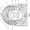
- a frontal view of a separating unit 7 of a combine harvester 1 that operates according to the axial flow principle is shown.
- the separating unit 7 has a rotatably mounted separating rotor 24 that is surrounded by a housing 25 arranged parallel to the separating rotor 24.
- the housing 25 comprises at least one sieve-like separating basket 26 that forms the separating area of the separating unit 7, and a cover 27, each of which surrounds the separating rotor 24 approximately halfway in the circumferential direction.
- several separating baskets 26 are arranged one behind the other in the axial direction parallel to the longitudinal axis 28 of the separating rotor 24.
- the separating rotor 24 is provided with driving elements 30 on its circumferential surface 29 for conveying the crop.
- the direction of rotation of the separating rotor 24 or the direction of crop flow is indicated by an arrow FR.
- the lateral surface 31 of the Fig. 2 The cover 27 shown is stepped, with the outer surface 31 in the Fig. 2 illustrated embodiment comprises a plurality of steps 33 arranged one behind the other in the circumferential direction or in the direction of rotation of the separating rotor 24.
- the steps 33 are each designed in the shape of a ramp, so that a crop flow guided along the lateral surface 31 is deflected by the steps 33 in the direction of the separating rotor 24.
- the steps 33 are arranged equidistantly from one another in the circumferential direction of the housing 25.
- the lateral surface 31 is designed in a stepped manner along its entire extent in the circumferential direction. Between two adjacent guide elements 32 there is a channel 34 through which the steps 33 extend.
- the lateral surface 31 consists of interconnected steps 33, so that a one-piece lateral surface 31 is formed.
- the lateral surface 31 comprises thirteen steps 33 arranged one behind the other.
- the lateral surface 31 can comprise at least seven steps 33, but preferably at least nine steps 33.
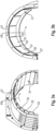
- Fig. 3a and 3b each show a cover 27 with a stepped outer surface 31, whereby the separating rotor 24, the separating basket 26 and the guide elements 32 are not shown here.
- Fig. 3a shows the design of the stepped outer surface 31 with a plurality of steps 33.
- the direction of rotation of the separating rotor 24 (not shown here) or the material flow direction is indicated by the arrow FR.
- Fig. 3b shows a version according to Fig. 3a alternative embodiment, wherein the stepped lateral surface 31 is formed by a plurality of edges 35.
- the lateral surface 31 comprises a plurality of flat sections 37.
- the flat sections 37 are each connected to one another to form an edge 35.
- the edges 35 extend axially parallel to the longitudinal axis 28 of the separator rotor 24.
- no guide elements 32 are shown, it is within the scope of the invention to arrange corresponding guide elements 32 on the side of the casing surface 31 facing the separating rotor 24.
- the casing surface 31 comprises seven flat sections 37 which are connected to one another to form six edges 35.
- Fig. 4 shows a cover 27 with a shell surface 31.
- the stepped shell surface 31 shown here comprises a plurality of edges 35.
- a rake 36 is located on the shell surface 31.
- the rake 36 is arranged downstream of the edges 35 when viewed in the intended material flow direction FR of the separating unit 7.
- the rake 36 comprises a plurality of fingers 38 which protrude in the radial direction towards the separating rotor 24. It is within the scope of the invention to arrange a corresponding rake 36 equally on a shell surface 31 with steps 33.
Landscapes
- Life Sciences & Earth Sciences (AREA)
- Environmental Sciences (AREA)
- Threshing Machine Elements (AREA)
Applications Claiming Priority (1)
| Application Number | Priority Date | Filing Date | Title |
|---|---|---|---|
| DE102023117474.6A DE102023117474A1 (de) | 2023-07-03 | 2023-07-03 | Abscheideaggregat für einen Mähdrescher |
Publications (1)
| Publication Number | Publication Date |
|---|---|
| EP4494450A1 true EP4494450A1 (fr) | 2025-01-22 |
Family
ID=91302081
Family Applications (1)
| Application Number | Title | Priority Date | Filing Date |
|---|---|---|---|
| EP24178499.0A Pending EP4494450A1 (fr) | 2023-07-03 | 2024-05-28 | Unité de séparation pour une moissonneuse-batteuse |
Country Status (2)
| Country | Link |
|---|---|
| EP (1) | EP4494450A1 (fr) |
| DE (1) | DE102023117474A1 (fr) |
Citations (3)
| Publication number | Priority date | Publication date | Assignee | Title |
|---|---|---|---|---|
| EP2428109B1 (fr) | 2010-09-09 | 2013-06-12 | CLAAS Selbstfahrende Erntemaschinen GmbH | Séparateur pour moissonneuse-batteuse |
| EP3714678A1 (fr) * | 2019-03-27 | 2020-09-30 | CLAAS Selbstfahrende Erntemaschinen GmbH | Séparateur axial pour une moissonneuse-batteuse |
| EP3479675B1 (fr) * | 2017-11-07 | 2021-06-23 | CNH Industrial Belgium NV | Cage de rotor avec des parois planes pour un véhicule agricole |
-
2023
- 2023-07-03 DE DE102023117474.6A patent/DE102023117474A1/de active Pending
-
2024
- 2024-05-28 EP EP24178499.0A patent/EP4494450A1/fr active Pending
Patent Citations (3)
| Publication number | Priority date | Publication date | Assignee | Title |
|---|---|---|---|---|
| EP2428109B1 (fr) | 2010-09-09 | 2013-06-12 | CLAAS Selbstfahrende Erntemaschinen GmbH | Séparateur pour moissonneuse-batteuse |
| EP3479675B1 (fr) * | 2017-11-07 | 2021-06-23 | CNH Industrial Belgium NV | Cage de rotor avec des parois planes pour un véhicule agricole |
| EP3714678A1 (fr) * | 2019-03-27 | 2020-09-30 | CLAAS Selbstfahrende Erntemaschinen GmbH | Séparateur axial pour une moissonneuse-batteuse |
Also Published As
| Publication number | Publication date |
|---|---|
| DE102023117474A1 (de) | 2025-01-09 |
Similar Documents
| Publication | Publication Date | Title |
|---|---|---|
| DE602004005553T2 (de) | System zum Ausstossen von Ernteresten aus einem Mähdrescher | |
| DE2628706C2 (fr) | ||
| EP2965614B1 (fr) | Boîtier de collecteur d'entrée | |
| DE2725588C2 (fr) | ||
| EP2594126B1 (fr) | Panier de séparation | |
| DE2430718A1 (de) | Dreschmaschine, insbesondere maehdrescher | |
| EP3753393B1 (fr) | Moissonneuse-batteuse automotrice | |
| EP3203829B1 (fr) | Dispositif pour traiter un produit récolté et procédé pour commander un flux de produit récolté dans ce dispositif | |
| EP2011384B1 (fr) | Unité de traitement de récoltes dotée d'un nombre de rotations dépendant du débit | |
| EP2428109B1 (fr) | Séparateur pour moissonneuse-batteuse | |
| EP1226747B1 (fr) | Tambour avec éléments entraíneurs interchangeables | |
| EP2071935B1 (fr) | Moissonneuse-batteuse dotée d'un ventilateur de nettoyage | |
| DE3025380A1 (de) | Maehdrescher | |
| DE102005027726A1 (de) | Radialgebläse für eine Reinigungseinrichtung für einen Mähdrescher | |
| EP3369301B1 (fr) | Moissonneuse | |
| EP4230024A1 (fr) | Moissonneuse-batteuse automotrice | |
| EP1214873A1 (fr) | Dispositif d'introduction pour moissonneuse à écoulement axial | |
| EP4151072A1 (fr) | Dispositif de séparation pour une moissonneuse-batteuse, ainsi que moissonneuse-batteuse dotée d'un tel dispositif de séparation | |
| EP3208466A1 (fr) | Soufflante de nettoyage avec carter en plastique et utilisation d'une méthode de moulage rotatif pour fabriquer un carter intégral | |
| EP3797577B1 (fr) | Moissonneuse-batteuse pourvue de capteur de grains restants | |
| EP4494450A1 (fr) | Unité de séparation pour une moissonneuse-batteuse | |
| EP4230025A1 (fr) | Moissonneuse-batteuse automotrice | |
| EP2805602A2 (fr) | Moissonneuse-batteuse | |
| DE102011088543B4 (de) | Mähdrescher mit einer zwischen der Drescheinrichtung und der Reinigung angeordneten Nachdrescheinrichtung | |
| EP4000378B1 (fr) | Machine de travail agricole dotée d'un tambour |
Legal Events
| Date | Code | Title | Description |
|---|---|---|---|
| PUAI | Public reference made under article 153(3) epc to a published international application that has entered the european phase |
Free format text: ORIGINAL CODE: 0009012 |
|
| STAA | Information on the status of an ep patent application or granted ep patent |
Free format text: STATUS: THE APPLICATION HAS BEEN PUBLISHED |
|
| AK | Designated contracting states |
Kind code of ref document: A1 Designated state(s): AL AT BE BG CH CY CZ DE DK EE ES FI FR GB GR HR HU IE IS IT LI LT LU LV MC ME MK MT NL NO PL PT RO RS SE SI SK SM TR |
|
| P01 | Opt-out of the competence of the unified patent court (upc) registered |
Free format text: CASE NUMBER: APP_6713/2025 Effective date: 20250210 |
|
| STAA | Information on the status of an ep patent application or granted ep patent |
Free format text: STATUS: REQUEST FOR EXAMINATION WAS MADE |
|
| 17P | Request for examination filed |
Effective date: 20250722 |