EP4494579A1 - Rotablatator - Google Patents
Rotablatator Download PDFInfo
- Publication number
- EP4494579A1 EP4494579A1 EP23826188.7A EP23826188A EP4494579A1 EP 4494579 A1 EP4494579 A1 EP 4494579A1 EP 23826188 A EP23826188 A EP 23826188A EP 4494579 A1 EP4494579 A1 EP 4494579A1
- Authority
- EP
- European Patent Office
- Prior art keywords
- drive shaft
- rotational atherectomy
- atherectomy device
- pumping liquid
- rotary grinding
- Prior art date
- Legal status (The legal status is an assumption and is not a legal conclusion. Google has not performed a legal analysis and makes no representation as to the accuracy of the status listed.)
- Pending
Links
Images

Classifications
-
- A—HUMAN NECESSITIES
- A61—MEDICAL OR VETERINARY SCIENCE; HYGIENE
- A61B—DIAGNOSIS; SURGERY; IDENTIFICATION
- A61B17/00—Surgical instruments, devices or methods
- A61B17/32—Surgical cutting instruments
- A61B17/3205—Excision instruments
- A61B17/3207—Atherectomy devices working by cutting or abrading; Similar devices specially adapted for non-vascular obstructions
- A61B17/320758—Atherectomy devices working by cutting or abrading; Similar devices specially adapted for non-vascular obstructions with a rotating cutting instrument, e.g. motor driven
-
- A—HUMAN NECESSITIES
- A61—MEDICAL OR VETERINARY SCIENCE; HYGIENE
- A61B—DIAGNOSIS; SURGERY; IDENTIFICATION
- A61B17/00—Surgical instruments, devices or methods
- A61B2017/00367—Details of actuation of instruments, e.g. relations between pushing buttons, or the like, and activation of the tool, working tip, or the like
- A61B2017/00398—Details of actuation of instruments, e.g. relations between pushing buttons, or the like, and activation of the tool, working tip, or the like using powered actuators, e.g. stepper motors, solenoids
-
- A—HUMAN NECESSITIES
- A61—MEDICAL OR VETERINARY SCIENCE; HYGIENE
- A61B—DIAGNOSIS; SURGERY; IDENTIFICATION
- A61B17/00—Surgical instruments, devices or methods
- A61B17/32—Surgical cutting instruments
- A61B2017/320004—Surgical cutting instruments abrasive
-
- A—HUMAN NECESSITIES
- A61—MEDICAL OR VETERINARY SCIENCE; HYGIENE
- A61B—DIAGNOSIS; SURGERY; IDENTIFICATION
- A61B17/00—Surgical instruments, devices or methods
- A61B17/32—Surgical cutting instruments
- A61B17/3205—Excision instruments
- A61B17/3207—Atherectomy devices working by cutting or abrading; Similar devices specially adapted for non-vascular obstructions
- A61B17/320758—Atherectomy devices working by cutting or abrading; Similar devices specially adapted for non-vascular obstructions with a rotating cutting instrument, e.g. motor driven
- A61B2017/320766—Atherectomy devices working by cutting or abrading; Similar devices specially adapted for non-vascular obstructions with a rotating cutting instrument, e.g. motor driven eccentric
-
- A—HUMAN NECESSITIES
- A61—MEDICAL OR VETERINARY SCIENCE; HYGIENE
- A61B—DIAGNOSIS; SURGERY; IDENTIFICATION
- A61B17/00—Surgical instruments, devices or methods
- A61B17/32—Surgical cutting instruments
- A61B17/3205—Excision instruments
- A61B17/3207—Atherectomy devices working by cutting or abrading; Similar devices specially adapted for non-vascular obstructions
- A61B17/320758—Atherectomy devices working by cutting or abrading; Similar devices specially adapted for non-vascular obstructions with a rotating cutting instrument, e.g. motor driven
- A61B2017/320775—Morcellators, impeller or propeller like means
-
- A—HUMAN NECESSITIES
- A61—MEDICAL OR VETERINARY SCIENCE; HYGIENE
- A61B—DIAGNOSIS; SURGERY; IDENTIFICATION
- A61B2217/00—General characteristics of surgical instruments
- A61B2217/002—Auxiliary appliance
- A61B2217/005—Auxiliary appliance with suction drainage system
-
- A—HUMAN NECESSITIES
- A61—MEDICAL OR VETERINARY SCIENCE; HYGIENE
- A61B—DIAGNOSIS; SURGERY; IDENTIFICATION
- A61B2217/00—General characteristics of surgical instruments
- A61B2217/002—Auxiliary appliance
- A61B2217/007—Auxiliary appliance with irrigation system
Definitions
- the present disclosure relates to the technical field of medical equipment, and in particular to a rotational atherectomy device.
- Atherosclerotic plaques are typically located in the vasculature of coronary arteries or peripheral arteries, and may have different characteristics depending on the texture of the plaques.
- Heavily calcified lesions need to be pretreated with an atherectomy device, of which the principle involves grinding up the vascular lesions by rotating a rotational atherectomy device at a high speed to ablate the calcified or fibrotic atherosclerotic plaques, thereby opening the blood vessels blocked by the plaques, obtaining an enlarged smooth vascular lumen, and thus facilitating subsequent stent implantation.
- the rotary grinding head is mainly propelled to rotate at a high speed by the rotational catheter via the drive shaft, and is advanced forward to contact, grind up, and thereby ablate the lesions. Since heat will be generated during the process of grinding up lesions, in order to reduce the thermal damage to blood vessel tissues and blood, during the rotary grinding process a cooling solution (such as saline) needs to be infused to cool and flush the debris and microparticles that are ground off.
- a cooling solution such as saline
- the rotational atherectomy device in the related art mainly delivers and infuses the cooling solution in the reservoir bag to the distal end of the catheter through a pressure bag or an infusion pump, playing a role in cooling and flushing the generated debris and microparticles, but cannot timely and effectively adjust the flow rate of the infusion of the cooling solution according to the actual rotational atherectomy situation.
- a rotational atherectomy device is provided to solve the issue that the flow rate of the infusion of the cooling solution cannot be timely and effectively adjusted.
- a rotational atherectomy device including:
- the proximal end is the end of the medical device that is close to the operator (such as a doctor), and the distal end is the end of the medical device away from the operator.
- the present disclosure provides a rotational atherectomy device, including:
- the drive shaft extends through the liquid feeding cavity, and the pumping liquid member is coaxially provided on the drive shaft.
- the pumping liquid member has at least one axial groove, the axial groove enables a peripheral side of the pumping liquid member to form at least one rotor blade, and the rotor blade is configured to deliver liquid toward the distal end of the liquid feeding pipe along the liquid feeding cavity when the pumping liquid member rotates.
- an outer diameter of the rotor blade gradually increases from a proximal end thereof to a distal end thereof.
- the liquid feeding pipe includes a guide cavity spaced apart from the liquid feeding cavity, and the drive shaft extends through the guide cavity and is in transmission connection with the pumping liquid member through a transmission mechanism.
- the transmission mechanism includes a gear transmission assembly
- the gear transmission assembly includes a driving wheel and a driven wheel engaged with each other, the driving wheel is connected to the drive shaft, and the driven wheel is connected to the pumping liquid member.
- the gear transmission assembly includes at least one intermediate gear engaged between the driving wheel and the driven wheel.
- a transmission ratio between the driving wheel and the driven wheel is greater than 1.
- a transmission ratio between the driving wheel and the driven wheel is in a range from 1.1:1 to 3: 1.
- the transmission mechanism includes a worm gear and a worm engaged with each other, the worm is coaxially connected to the drive shaft, and the pumping liquid member includes a plurality of rotor blades connected to the worm gear, when the worm drives the worm gear to rotate, the worm gear drives the plurality of rotor blades to rotate.
- the surface where the rotor blade is located are inclined to an axial direction of the pumping liquid member.
- a rotation axis of the pumping liquid member is parallel to and spaced apart from the drive shaft.
- the rotational atherectomy device further includes a liquid inlet pipeline in communication with the liquid feeding cavity.
- the rotational atherectomy device further includes a drive assembly, the drive assembly is connected to a proximal end of the drive shaft and is configured to drive the drive shaft to rotate.
- the drive assembly is an electric motor or a pneumatic motor.
- the rotational atherectomy device further includes a guide wire extending through the drive shaft and the rotary grinding assembly, wherein the drive shaft and the rotary grinding assembly can move axially along the guide wire and rotate around the guide wire.
- the rotary grinding assembly includes a rotary grinding head, at least a portion of a surface of the rotary grinding head is covered with abrasive particles.
- the abrasive particles include diamond particles.
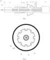
- a rotational atherectomy device 10 includes a rotary grinding assembly 11, a drive shaft 12, a guide wire 13, a liquid feeding pipe 14, a pumping liquid member 15, a liquid inlet pipeline 16, and a drive assembly 17.
- the rotary grinding assembly 11 is connected to a distal end of the drive shaft 12, and the guide wire 13 extends through the rotary grinding assembly 11 and the drive shaft 12.
- the drive shaft 12 and the rotary grinding assembly 11 can move axially along the guide wire 13, and the drive shaft 12 and the rotary grinding assembly 11 can rotate around the guide wire 13.
- the drive shaft 12 and the rotary grinding assembly 11 when performing the rotational atherectomy operation, can be operated to move back and forth along the guide wire 13.
- the "move axially” refers to moving toward the distal and proximal ends along the guide wire 13 to perform a rotational atherectomy on the position where the lumen (e.g., a blood vessel) needs the rotational atherectomy, so as to unclog the lumen.
- the rotary grinding assembly 11 includes a rotary grinding head, and at least a portion of the surface of the rotary grinding head is covered with abrasive particles.
- the abrasive particles include, but are not limited to, diamond particles, such that a good rotary grinding effect can be obtained during the rotation of the rotary grinding head along with the drive shaft 12.
- the guide wire 13 is not an essential structure, which can be omitted.
- the liquid inlet line 16 is configured to input a cooling solution, the cooling solution includes, but is not limited to saline.
- the cooling solution is saline as an example.
- the liquid inlet pipeline 16 is in communication with the liquid feeding pipe 14.
- the saline is delivered to the distal end through the liquid feeding cavity 141 of the liquid feeding pipe 14 to flow out, so as to flush the microparticles generated by the rotary grinding and take away the heat generated by the rotary grinding, thereby reducing the temperature rise caused by the rotation of the rotary grinding assembly 11 and the resulting thermal damage to blood vessel tissues and blood, and thus avoiding complications such as slow blood flow/no reflow.
- the pumping liquid member 15 is an element capable of pumping liquid. Specifically, the pumping liquid member 15 is in transmission connection with the drive shaft 12, such that the pumping liquid member 15 can be driven by the drive shaft 12 to rotate, so as to pump liquid.
- the drive assembly 17 is connected to the drive shaft 12. Driven by the drive assembly 17, the drive shaft 12 drives the pumping liquid member 15 and the rotary grinding assembly 11 to rotate.
- the pumping liquid member 15 is coaxially provided on the drive shaft 12, so that when the drive shaft 12 is driven by the drive assembly 17 to rotate, the pumping liquid member 15 can rotate along with the drive shaft 12.
- the flow rate of saline can be controlled by controlling the rotation speed of the pumping liquid member 15. Since the power sources of the pumping liquid member 15 and the drive shaft 12 are both the drive assembly 17, the rotational atherectomy device 10 can change the amount of saline delivered to the distal end of the rotational atherectomy device 10 by changing the rotation speed of the drive shaft 12.
- the pumping liquid member 15 since the pumping liquid member 15 is coaxially provided on the drive shaft 12, as the rotation speed of the drive shaft 12 increases, the pumping liquid member 15 increases the amount of saline delivered and infused at the distal end, thereby increasing the flow rate of saline to flush the debris and microparticles generated during the rotary grinding of the rotary grinding assembly 11, and reduce the temperature rise caused by the rotation of the rotary grinding assembly 11 and the resulting thermal damage caused to blood vessel tissue and blood, and thus avoid complications such as slow blood flow/no reflow.
- a liquid feeding cavity 141 is formed between an outer wall of the drive shaft 12 and an inner wall of the liquid feeding pipe 14.
- the liquid feeding cavity 141 can not only deliver saline to the distal end of the rotational atherectomy device 10 to wash away the debris generated during the rotary grinding, but also take away the heat generated during the rotation of the drive shaft 12 to cool the drive shaft 12, thereby reducing the temperature rise caused by the rotation of the rotary grinding assembly 11 and the resulting thermal damage to blood vessel tissues and blood, and thus avoiding complications such as slow blood flow/no reflow.
- a rotation axis of the pumping liquid member 15 coincides with the guide wire 13.
- the pumping liquid member 15 rotates about the guide wire 13.
- the rotation axis of the pumping liquid member 15 is an axis around which the pumping liquid member 15 rotates.
- the liquid feeding pipe 14 may be a single pipe piece or may be formed by combining a plurality of pipe pieces.
- a diameter of a portion of the liquid feeding pipe 14 corresponding to the pumping liquid member 15 may be set to be larger than that of the other portions, so as to facilitate the mounting of the pumping liquid member 15.
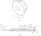
- the pumping liquid member 15 has at least one axial groove 151, which enables a peripheral side of the pumping liquid member 15 to form at least one rotor blade 152.
- the rotor blade 152 pushes the saline along the liquid feeding cavity 141 toward the distal end of the liquid feeding pipe 14, and finally enables the saline to be discharged from the distal end of the liquid feeding pipe 14.
- the distal end of the liquid feeding pipe 14 is located at the position of the rotary grinding. Specifically, the debris generated during the rotary grinding of the rotary grinding assembly 11 can be flushed by the saline output from the liquid feeding pipe 14.
- an outer diameter of the rotor blade 152 gradually increases from the proximal end to the distal end.
- the saline can flow through the surface of the rotor blade 152 via the liquid feeding cavity 141.
- the liquid pressure is lower where the flow rate at the distal end of the pumping liquid member 15 is larger, and the liquid pressure is higher where the flow rate at the proximal end of the pumping liquid member 15 is lower. Under the action of the pressure difference, the liquid is accelerated to flow from the proximal end to the distal end. Therefore, the use of such pumping liquid member 15 can improve the delivery performance of saline, and facilitate the delivery of saline along the liquid feeding pipe 14 to the rotary grinding position at the distal end.
- the saline always flows toward the distal end along the liquid feeding pipe 14. Therefore, during the rotary grinding process, the flow rate of the saline increases with the increase of the rotation speed of the worm gear, and is not affected by the rotation direction of the pumping liquid member 15.
- the pumping liquid member 15 has eight rotor blades 152. In some embodiments, the pumping liquid member 15 has more rotor blades 152, for example, 9 or 10. The number of rotor blades 152 of the pumping liquid member 15 is not limited herein.
- the rotation speeds of the drive shaft 12, the rotary grinding assembly 11 and the pumping liquid member 15 that are of the rotational atherectomy device 10 are the same, and the rotation speed is obtained from the drive assembly 17.
- the drive assembly 17 may be an electric motor or a pneumatic motor, as long as it can drive the drive shaft 12 to rotate.
- the rotation speed of the rotary grinding assembly 11 driven by the drive assembly 17 is in a range from 1000 rad/min to 200,000 rad/min, such as 1,000 rad/min, 2,000 rad/min, 5,000 rad/min, 10,000 rad/min, 15,000 rad/min, 150,000 rad/min, 170,000 rad/min, or 200,000 rad/min.
- the flow rate of saline delivered from the liquid feeding cavity 141 of the liquid feeding pipe 14 to the distal end of the rotational atherectomy device 10 is in a range from 0.1 ml/min to 100 ml/min.
- the rotation speed of the rotary grinding assembly 11 is 200,000 rad/min
- the flow rate of saline generated by the rotation of the pumping liquid member 15 is 50 ml/min, so that the effect of the rotary grinding performed by the rotary grinding assembly 11 is ensured, and the saline is effectively used to flush the debris generated by the rotary grinding.
- the rotational atherectomy device 20 according to the second embodiment is similar to the rotational atherectomy device 10 according to the first embodiment, and the rotational atherectomy device 20 includes a rotary grinding assembly 21, a drive shaft 22, a guide wire 23, a liquid feeding pipe 24, a pumping liquid member 25, a liquid inlet pipeline 26, and a drive assembly 27.
- the guide wire 23 is not an essential structure. In the embodiment in which the rotational atherectomy device 20 includes the guide wire 23, as shown in FIGS. 4 and 5 , the guide wire 23 extends through the rotary grinding assembly 21 and the drive shaft 22.
- the drive shaft 22 and the rotary grinding assembly 21 can move axially along the guide wire 23, and the drive shaft 22 and the rotary grinding assembly 21 can rotate around the guide wire 23.
- the pumping liquid member 25 and the drive shaft 22 are not coaxial.
- the rotational atherectomy device 20 includes a transmission mechanism, through which the pumping liquid member 25 is in transmission connection with the drive shaft 22.
- the drive shaft 22 can drive the pumping liquid member 25 to rotate through the transmission mechanism.
- the pumping liquid member 25 can deliver saline toward the distal end through the liquid feeding pipe 24 to the rotary grinding position.
- the pumping liquid member 25 Since the pumping liquid member 25 is in transmission connection with the drive shaft 22 by the transmission mechanism, when the drive shaft 22 accelerates, the pumping liquid member 25 also accelerates together, so as to increase the flow rate of saline flushing the debris and microparticles, thereby reducing the temperature rise caused by the high-speed rotation of the rotary grinding head and the resulting thermal damage to blood vessel tissues and blood, and thus avoiding complications such as slow blood flow/no reflow.
- the transmission mechanism includes, but is not limited to, a gear transmission assembly.
- the gear transmission assembly includes a driving wheel 28 and a driven wheel 29 that engage with each other.
- the driving wheel 28 is connected to the drive shaft 22, and the driven wheel 29 is connected to the pumping liquid member 25.
- the driven wheel 29 is connected to the pumping liquid member 25 through a transmission shaft.
- the driving wheel 28 is engaged with and drives the driven wheel 29 to rotate, so that the driven wheel 29 drives the pumping liquid member 25 to rotate through the transmission shaft.
- the transmission ratio between the driving wheel 28 and the driven wheel 29 is greater than 1, so that when the drive shaft 22 rotates, the driven wheel 29 can transmit as much torque as possible to the pumping liquid member 25 via the transmission shaft, so that the pump liquid member 25 has enough thrust force to deliver the saline through the liquid feeding pipe 24 to the rotary grinding position.
- the transmission ratio between the driving wheel 28 and the driven wheel 29 may be specifically in a range from 1.1:1 to 3: 1.
- the transmission ratio between the driving wheel 28 and the driven wheel 29 may also be less than or equal to 1.
- the pumping liquid member 25 When the transmission ratio between the driving wheel 28 and the driven wheel 29 is equal to 1, the pumping liquid member 25 always maintains the same rotation speed as the drive shaft 22 during the rotation of the drive shaft 22.
- the transmission ratio between the driving wheel 28 and the driven wheel 29 is less than 1, during the rotation of the drive shaft 22, the pumping liquid member 25 can inject the saline into the liquid feeding pipe 24 at a rotation speed greater than that of the drive shaft 22, thereby effectively increasing the flow rate of saline for flushing the debris and microparticles.
- the gear transmission assembly is not limited to a structure in which the driving wheel 28 and the driven wheel 29 are engaged.
- the gear transmission assembly further includes at least one intermediate gear, and the intermediate gear is engaged between the driving wheel 28 and the driven wheel 29, such that there is a suitable transmission ratio between the driving wheel 28 and the driven wheel 29.
- the transmission mechanism may be a worm gear-worm transmission structure.
- the transmission mechanism includes a worm gear and a worm that are engaged with each other.
- the worm is coaxially connected to the drive shaft 22, so that when the drive shaft 22 rotates, the worm drives the worm gear to rotate.
- the torque of the drive shaft 22 can be transmitted to the pumping liquid member 25 by means of the worm of the transmission mechanism driving the worm gear, so as to realize the transmission connection between the drive shaft 22 and the pumping liquid member 25.
- the pumping liquid member 25 includes a plurality of rotor blades 251, and the plurality of rotor blades 251 are connected to the worm gear.
- the rotor blades 251 located on the worm gear also rotate together, thereby realizing the delivery of saline to the rotary grinding position through the liquid feeding pipe 24, and flushing the debris generated in the rotary grinding process as an example.
- the rotation axis of the pumping liquid member 25 does not coincide with the drive shaft 22.
- they are parallel to and spaced apart from each other.
- the liquid feeding cavity 241 for providing the pumping liquid member 25 does not coincide with the drive shaft 22.
- an independent liquid feeding cavity 241 is formed by the liquid feeding pipe 24 sleeved outside the drive shaft 22.
- the liquid feeding pipe 24 includes at least two pipe cavities separated from each other. Taking the liquid feeding pipe 24 including two pipe cavities as an example, as shown in FIG.
- one of the two pipe cavities is used as the liquid feeding cavity 241 for delivering saline, and the other one can be used as the guide cavity 242 for the drive shaft 22, and the drive shaft 22 has good stability when moving in the axial direction under the guidance of the guide cavity 242.
- the pumping liquid member 25 includes a plurality of oblique rotor blades 251. Specifically, the surfaces where the rotor blades 251 are located are inclined rather than perpendicular to the axial direction of the pumping liquid member 25, similar to the blades of a fan.
- the rotor blades 251 when rotates, can increase the flow rate of the liquid in the liquid feeding cavity 241.
- the flow direction of the saline driven by the pumping liquid member 25 is related to the rotation direction of the pumping liquid member 25, the flow direction of the saline can be adjusted by controlling the rotation direction of the drive shaft 22.
- the number of the rotor blades 251 of the pumping liquid member 25 may be specifically four, or may be two or three, and the number of the rotor blades 251 is not limited herein.
- the rotation speed of the drive shaft 22 is 200,000 rad/min
- the rotation speed of the pumping liquid member 25 is 20,000 rad/min
- the flow rate of saline generated by the rotation of the pumping liquid member 25 is 30 ml/min. It should be noted that, in some other embodiments, the rotation speed of the drive shaft 22 and the rotation speed of the pumping liquid member 25 may be other values.
- the rotation speed of the drive shaft 22 is in a range from 150,000 rad/min to 250,000 rad/min, and the rotation speed of the pumping liquid member 25 is 1/10 to 1/2 of the rotation speed of the drive shaft 22, which is not limited herein.
- the drive assembly 27 may be an electric motor or a pneumatic motor, which is not limited herein.
- first and second are used for descriptive purposes only, which cannot be construed as indicating or implying a relative importance, or implicitly specifying the number of the indicated technical features.
- the features defined with “first” and “second” may explicitly or implicitly include at least one feature.
- a plurality of means two or more, such as two or three, unless otherwise defined explicitly and specifically.
- the terms “install”, “connect”, “join”, and “fix” should be understood in a broad sense.
- they may refer to a fixed connection, a detachable connection, or an integral connection, may refer to a mechanical connection or electrical connection, and may refer to a direct connection, an indirect connection via an intermediate medium, an internal connection between two elements, or interaction between two elements.
- a first feature being "on” or “under” a second feature may be the case that the first feature is in direct contact with the second feature, or the first feature is in indirect contact with the second feature via an intermediate medium.
Landscapes
- Health & Medical Sciences (AREA)
- Surgery (AREA)
- Life Sciences & Earth Sciences (AREA)
- Biomedical Technology (AREA)
- Nuclear Medicine, Radiotherapy & Molecular Imaging (AREA)
- Engineering & Computer Science (AREA)
- Vascular Medicine (AREA)
- Heart & Thoracic Surgery (AREA)
- Medical Informatics (AREA)
- Molecular Biology (AREA)
- Animal Behavior & Ethology (AREA)
- General Health & Medical Sciences (AREA)
- Public Health (AREA)
- Veterinary Medicine (AREA)
- Surgical Instruments (AREA)
Applications Claiming Priority (2)
| Application Number | Priority Date | Filing Date | Title |
|---|---|---|---|
| CN202210696567.1A CN114948107A (zh) | 2022-06-20 | 2022-06-20 | 旋磨装置 |
| PCT/CN2023/099612 WO2023246539A1 (zh) | 2022-06-20 | 2023-06-12 | 旋磨装置 |
Publications (2)
| Publication Number | Publication Date |
|---|---|
| EP4494579A1 true EP4494579A1 (de) | 2025-01-22 |
| EP4494579A4 EP4494579A4 (de) | 2025-07-02 |
Family
ID=82964047
Family Applications (1)
| Application Number | Title | Priority Date | Filing Date |
|---|---|---|---|
| EP23826188.7A Pending EP4494579A4 (de) | 2022-06-20 | 2023-06-12 | Rotablatator |
Country Status (4)
| Country | Link |
|---|---|
| US (1) | US20250255641A1 (de) |
| EP (1) | EP4494579A4 (de) |
| CN (1) | CN114948107A (de) |
| WO (1) | WO2023246539A1 (de) |
Families Citing this family (2)
| Publication number | Priority date | Publication date | Assignee | Title |
|---|---|---|---|---|
| CN114948107A (zh) * | 2022-06-20 | 2022-08-30 | 上海微创旋律医疗科技有限公司 | 旋磨装置 |
| CN117547330A (zh) * | 2023-11-17 | 2024-02-13 | 上海微创医疗器械(集团)有限公司 | 旋磨装置、旋磨设备和旋磨转速获取方法 |
Family Cites Families (27)
| Publication number | Priority date | Publication date | Assignee | Title |
|---|---|---|---|---|
| US5284486A (en) * | 1991-06-11 | 1994-02-08 | Microvena Corporation | Self-centering mechanical medical device |
| US5524180A (en) * | 1992-08-10 | 1996-06-04 | Computer Motion, Inc. | Automated endoscope system for optimal positioning |
| US5490859A (en) * | 1992-11-13 | 1996-02-13 | Scimed Life Systems, Inc. | Expandable intravascular occlusion material removal devices and methods of use |
| US6217595B1 (en) * | 1996-11-18 | 2001-04-17 | Shturman Cardiology Systems, Inc. | Rotational atherectomy device |
| US8920402B2 (en) * | 2004-04-27 | 2014-12-30 | The Spectranetics Corporation | Thrombectomy and soft debris removal device |
| US8011551B2 (en) * | 2008-07-01 | 2011-09-06 | Tyco Healthcare Group Lp | Retraction mechanism with clutch-less drive for use with a surgical apparatus |
| US9808146B2 (en) * | 2011-12-02 | 2017-11-07 | Interscope, Inc. | Endoscopic tool for debriding and removing polyps |
| US9546662B2 (en) * | 2012-11-20 | 2017-01-17 | Smith & Nephew, Inc. | Medical pump |
| US10052122B2 (en) * | 2014-01-17 | 2018-08-21 | Cardiovascular Systems, Inc. | Spin-to-open atherectomy device with electric motor control |
| US10405878B2 (en) * | 2014-07-25 | 2019-09-10 | Boston Scientific Scimed, Inc. | Rotatable medical device |
| WO2016089847A1 (en) * | 2014-12-04 | 2016-06-09 | Boston Scientific Scimed, Inc. | Rotatable medical device |
| JP2016221081A (ja) * | 2015-06-02 | 2016-12-28 | テルモ株式会社 | 医療デバイス |
| US10307175B2 (en) * | 2016-03-26 | 2019-06-04 | Rex Medical, L.P | Atherectomy device |
| EP3808403A1 (de) * | 2016-07-21 | 2021-04-21 | Tc1 Llc | Fluiddichtungen für katheterpumpenmotoranordnung |
| CN110582242B (zh) * | 2017-05-03 | 2023-03-10 | 美敦力瓦斯科尔勒公司 | 组织移除导管 |
| EP3723634B1 (de) * | 2017-12-12 | 2024-02-28 | Boston Scientific Scimed, Inc. | Medizinische drehvorrichtung |
| EP3817673B1 (de) * | 2018-08-07 | 2024-11-20 | Cardio Flow, Inc. | Atherektomievorrichtungen |
| EP3911255B1 (de) * | 2019-01-18 | 2023-03-01 | Boston Scientific Scimed Inc. | Getriebe für atherektomiesystem |
| US11337724B2 (en) * | 2019-03-15 | 2022-05-24 | Terumo Kabushiki Kaisha | Method and system for controlling rotational speed of an agitator or catheter |
| CN211132606U (zh) * | 2019-08-01 | 2020-07-31 | 杨礼瑾 | 动力源可置于人体内的旋转传动导管 |
| DE112020000311T5 (de) * | 2020-07-03 | 2022-02-24 | Vascupatent Medical (Shenzhen) Co., Ltd | Rotationsschleifvorrichtung für intravaskuläre verkalkte läsionen |
| CN113288334B (zh) * | 2021-05-28 | 2023-08-04 | 福建珞创医疗科技有限公司 | 心血管介入手术装置 |
| CN113855165A (zh) * | 2021-11-11 | 2021-12-31 | 上海融脉医疗科技有限公司 | 一种机械血栓切除导管装置 |
| CN216455184U (zh) * | 2021-12-02 | 2022-05-10 | 贵州梓锐科技有限公司 | 一种手术用磨头 |
| CN216535426U (zh) * | 2021-12-02 | 2022-05-17 | 贵州梓锐科技有限公司 | 一种手术用冷却磨头 |
| CN217793252U (zh) * | 2022-06-20 | 2022-11-15 | 上海微创旋律医疗科技有限公司 | 旋磨装置 |
| CN114948107A (zh) * | 2022-06-20 | 2022-08-30 | 上海微创旋律医疗科技有限公司 | 旋磨装置 |
-
2022
- 2022-06-20 CN CN202210696567.1A patent/CN114948107A/zh active Pending
-
2023
- 2023-06-12 WO PCT/CN2023/099612 patent/WO2023246539A1/zh not_active Ceased
- 2023-06-12 US US18/857,131 patent/US20250255641A1/en active Pending
- 2023-06-12 EP EP23826188.7A patent/EP4494579A4/de active Pending
Also Published As
| Publication number | Publication date |
|---|---|
| EP4494579A4 (de) | 2025-07-02 |
| CN114948107A (zh) | 2022-08-30 |
| US20250255641A1 (en) | 2025-08-14 |
| WO2023246539A1 (zh) | 2023-12-28 |
Similar Documents
| Publication | Publication Date | Title |
|---|---|---|
| EP4494579A1 (de) | Rotablatator | |
| JP7062140B2 (ja) | 継続的な浸軟および吸引を伴う断続二重作用(研磨および切断)力のためのシステム、およびデバイス | |
| EP2922482B1 (de) | Medizinische pumpe | |
| CA1302829C (en) | Single-stage axial flow blood pump | |
| US5116350A (en) | Catheter system having distal tip for opening obstructions | |
| US7713235B2 (en) | Interventional catheters incorporating an active aspiration system | |
| US20180280005A1 (en) | Ultrasonic Endovascular Catheter with Expandable Portion | |
| US20110118660A1 (en) | Interventional catheters incorporating an active aspiration system | |
| CN110573099A (zh) | 组织移除导管 | |
| US10702300B2 (en) | Methods, devices and systems for slow rotation of drive shaft driven atherectomy systems | |
| CN114098903A (zh) | 一种轨道式机械血栓抽吸导管 | |
| CN113288334A (zh) | 基于钙化组织去除、回收及降温一体化的心血管介入手术装置的工作方法 | |
| WO2019188657A1 (ja) | 医療デバイス | |
| EP4238516B1 (de) | Antriebsvorrichtung und rotationsschleifvorrichtung | |
| CN217793252U (zh) | 旋磨装置 | |
| CN117562629A (zh) | 医用旋磨装置及旋磨方法 | |
| WO2025102421A1 (zh) | 旋磨导管及旋磨设备 | |
| CN115581511B (zh) | 旋磨系统及旋磨组件 | |
| CN216823579U (zh) | 一种轨道式机械血栓抽吸导管 | |
| CN120392243A (zh) | 血管旋切疏通装置 | |
| CN116250900A (zh) | 旋磨系统及其驱动手柄 | |
| CN121338209A (zh) | 导管手柄及导管装置 | |
| CN120227579A (zh) | 泵体及介入式导管泵系统 | |
| CN118021388A (zh) | 血管内凝塞物清除系统的旋转体 |
Legal Events
| Date | Code | Title | Description |
|---|---|---|---|
| STAA | Information on the status of an ep patent application or granted ep patent |
Free format text: STATUS: THE INTERNATIONAL PUBLICATION HAS BEEN MADE |
|
| PUAI | Public reference made under article 153(3) epc to a published international application that has entered the european phase |
Free format text: ORIGINAL CODE: 0009012 |
|
| STAA | Information on the status of an ep patent application or granted ep patent |
Free format text: STATUS: REQUEST FOR EXAMINATION WAS MADE |
|
| 17P | Request for examination filed |
Effective date: 20241017 |
|
| AK | Designated contracting states |
Kind code of ref document: A1 Designated state(s): AL AT BE BG CH CY CZ DE DK EE ES FI FR GB GR HR HU IE IS IT LI LT LU LV MC ME MK MT NL NO PL PT RO RS SE SI SK SM TR |
|
| A4 | Supplementary search report drawn up and despatched |
Effective date: 20250603 |
|
| RIC1 | Information provided on ipc code assigned before grant |
Ipc: A61B 17/3207 20060101AFI20250527BHEP |
|
| DAV | Request for validation of the european patent (deleted) | ||
| DAX | Request for extension of the european patent (deleted) |