EP3808403A1 - Fluiddichtungen für katheterpumpenmotoranordnung - Google Patents
Fluiddichtungen für katheterpumpenmotoranordnung Download PDFInfo
- Publication number
- EP3808403A1 EP3808403A1 EP20210775.1A EP20210775A EP3808403A1 EP 3808403 A1 EP3808403 A1 EP 3808403A1 EP 20210775 A EP20210775 A EP 20210775A EP 3808403 A1 EP3808403 A1 EP 3808403A1
- Authority
- EP
- European Patent Office
- Prior art keywords
- assembly
- motor
- fluid
- motor assembly
- catheter
- Prior art date
- Legal status (The legal status is an assumption and is not a legal conclusion. Google has not performed a legal analysis and makes no representation as to the accuracy of the status listed.)
- Pending
Links
Images








Classifications
-
- A—HUMAN NECESSITIES
- A61—MEDICAL OR VETERINARY SCIENCE; HYGIENE
- A61M—DEVICES FOR INTRODUCING MEDIA INTO, OR ONTO, THE BODY; DEVICES FOR TRANSDUCING BODY MEDIA OR FOR TAKING MEDIA FROM THE BODY; DEVICES FOR PRODUCING OR ENDING SLEEP OR STUPOR
- A61M60/00—Blood pumps; Devices for mechanical circulatory actuation; Balloon pumps for circulatory assistance
- A61M60/40—Details relating to driving
- A61M60/403—Details relating to driving for non-positive displacement blood pumps
- A61M60/408—Details relating to driving for non-positive displacement blood pumps the force acting on the blood contacting member being mechanical, e.g. transmitted by a shaft or cable
- A61M60/411—Details relating to driving for non-positive displacement blood pumps the force acting on the blood contacting member being mechanical, e.g. transmitted by a shaft or cable generated by an electromotor
- A61M60/414—Details relating to driving for non-positive displacement blood pumps the force acting on the blood contacting member being mechanical, e.g. transmitted by a shaft or cable generated by an electromotor transmitted by a rotating cable, e.g. for blood pumps mounted on a catheter
-
- A—HUMAN NECESSITIES
- A61—MEDICAL OR VETERINARY SCIENCE; HYGIENE
- A61M—DEVICES FOR INTRODUCING MEDIA INTO, OR ONTO, THE BODY; DEVICES FOR TRANSDUCING BODY MEDIA OR FOR TAKING MEDIA FROM THE BODY; DEVICES FOR PRODUCING OR ENDING SLEEP OR STUPOR
- A61M60/00—Blood pumps; Devices for mechanical circulatory actuation; Balloon pumps for circulatory assistance
- A61M60/80—Constructional details other than related to driving
- A61M60/802—Constructional details other than related to driving of non-positive displacement blood pumps
- A61M60/827—Sealings between moving parts
- A61M60/829—Sealings between moving parts having a purge fluid supply
-
- A—HUMAN NECESSITIES
- A61—MEDICAL OR VETERINARY SCIENCE; HYGIENE
- A61M—DEVICES FOR INTRODUCING MEDIA INTO, OR ONTO, THE BODY; DEVICES FOR TRANSDUCING BODY MEDIA OR FOR TAKING MEDIA FROM THE BODY; DEVICES FOR PRODUCING OR ENDING SLEEP OR STUPOR
- A61M25/00—Catheters; Hollow probes
- A61M25/0021—Catheters; Hollow probes characterised by the form of the tubing
- A61M25/0023—Catheters; Hollow probes characterised by the form of the tubing by the form of the lumen, e.g. cross-section, variable diameter
- A61M25/0026—Multi-lumen catheters with stationary elements
-
- A—HUMAN NECESSITIES
- A61—MEDICAL OR VETERINARY SCIENCE; HYGIENE
- A61M—DEVICES FOR INTRODUCING MEDIA INTO, OR ONTO, THE BODY; DEVICES FOR TRANSDUCING BODY MEDIA OR FOR TAKING MEDIA FROM THE BODY; DEVICES FOR PRODUCING OR ENDING SLEEP OR STUPOR
- A61M60/00—Blood pumps; Devices for mechanical circulatory actuation; Balloon pumps for circulatory assistance
- A61M60/10—Location thereof with respect to the patient's body
- A61M60/122—Implantable pumps or pumping devices, i.e. the blood being pumped inside the patient's body
- A61M60/126—Implantable pumps or pumping devices, i.e. the blood being pumped inside the patient's body implantable via, into, inside, in line, branching on, or around a blood vessel
- A61M60/13—Implantable pumps or pumping devices, i.e. the blood being pumped inside the patient's body implantable via, into, inside, in line, branching on, or around a blood vessel by means of a catheter allowing explantation, e.g. catheter pumps temporarily introduced via the vascular system
-
- A—HUMAN NECESSITIES
- A61—MEDICAL OR VETERINARY SCIENCE; HYGIENE
- A61M—DEVICES FOR INTRODUCING MEDIA INTO, OR ONTO, THE BODY; DEVICES FOR TRANSDUCING BODY MEDIA OR FOR TAKING MEDIA FROM THE BODY; DEVICES FOR PRODUCING OR ENDING SLEEP OR STUPOR
- A61M60/00—Blood pumps; Devices for mechanical circulatory actuation; Balloon pumps for circulatory assistance
- A61M60/20—Type thereof
- A61M60/205—Non-positive displacement blood pumps
- A61M60/216—Non-positive displacement blood pumps including a rotating member acting on the blood, e.g. impeller
-
- A—HUMAN NECESSITIES
- A61—MEDICAL OR VETERINARY SCIENCE; HYGIENE
- A61M—DEVICES FOR INTRODUCING MEDIA INTO, OR ONTO, THE BODY; DEVICES FOR TRANSDUCING BODY MEDIA OR FOR TAKING MEDIA FROM THE BODY; DEVICES FOR PRODUCING OR ENDING SLEEP OR STUPOR
- A61M60/00—Blood pumps; Devices for mechanical circulatory actuation; Balloon pumps for circulatory assistance
- A61M60/40—Details relating to driving
- A61M60/403—Details relating to driving for non-positive displacement blood pumps
- A61M60/422—Details relating to driving for non-positive displacement blood pumps the force acting on the blood contacting member being electromagnetic, e.g. using canned motor pumps
-
- A—HUMAN NECESSITIES
- A61—MEDICAL OR VETERINARY SCIENCE; HYGIENE
- A61M—DEVICES FOR INTRODUCING MEDIA INTO, OR ONTO, THE BODY; DEVICES FOR TRANSDUCING BODY MEDIA OR FOR TAKING MEDIA FROM THE BODY; DEVICES FOR PRODUCING OR ENDING SLEEP OR STUPOR
- A61M60/00—Blood pumps; Devices for mechanical circulatory actuation; Balloon pumps for circulatory assistance
- A61M60/80—Constructional details other than related to driving
- A61M60/802—Constructional details other than related to driving of non-positive displacement blood pumps
- A61M60/804—Impellers
- A61M60/806—Vanes or blades
- A61M60/808—Vanes or blades specially adapted for deformable impellers, e.g. expandable impellers
-
- A—HUMAN NECESSITIES
- A61—MEDICAL OR VETERINARY SCIENCE; HYGIENE
- A61M—DEVICES FOR INTRODUCING MEDIA INTO, OR ONTO, THE BODY; DEVICES FOR TRANSDUCING BODY MEDIA OR FOR TAKING MEDIA FROM THE BODY; DEVICES FOR PRODUCING OR ENDING SLEEP OR STUPOR
- A61M25/00—Catheters; Hollow probes
- A61M25/0067—Catheters; Hollow probes characterised by the distal end, e.g. tips
- A61M25/0074—Dynamic characteristics of the catheter tip, e.g. openable, closable, expandable or deformable
- A61M2025/0079—Separate user-activated means, e.g. guidewires, guide tubes, balloon catheters or sheaths, for sealing off an orifice, e.g. a lumen or side holes, of a catheter
-
- A—HUMAN NECESSITIES
- A61—MEDICAL OR VETERINARY SCIENCE; HYGIENE
- A61M—DEVICES FOR INTRODUCING MEDIA INTO, OR ONTO, THE BODY; DEVICES FOR TRANSDUCING BODY MEDIA OR FOR TAKING MEDIA FROM THE BODY; DEVICES FOR PRODUCING OR ENDING SLEEP OR STUPOR
- A61M25/00—Catheters; Hollow probes
- A61M25/10—Balloon catheters
- A61M25/1018—Balloon inflating or inflation-control devices
- A61M2025/1022—Balloon inflating or inflation-control devices driven by a rotary motor-activated pump
Definitions
- This application is directed to catheter pumps for mechanical circulatory support of a heart.
- Heart disease is a major health problem that has high mortality rate. Physicians increasingly use mechanical circulatory support systems for treating heart failure. The treatment of acute heart failure requires a device that can provide support to the patient quickly. Physicians desire treatment options that can be deployed quickly and minimally-invasively.
- a heart pump that can be placed minimally-invasively, for example, through an 18FR, 14FR, or 8FR incision. In one aspect, there is a need for a heart pump that can provide an average flow rate of 4 Lpm or more during operation, for example, at 62 mmHg of aortic pressure.
- a catheter pump system in one embodiment, can include a shaft assembly and an impeller coupled with a distal portion of the shaft assembly.
- the catheter pump system can include a motor assembly comprising a motor configured to impart rotation to the impeller through the shaft assembly.
- the catheter pump system can include a fluid pathway for supplying a fluid from outside the body, the fluid pathway conveying at least a portion of the supplied fluid proximally during operation of the catheter pump system.
- the catheter pump system can include a guidewire guide tube disposed in the lumen, the guidewire guide tube configured to receive a guidewire therein for guiding the impeller to a target site of a patient.
- the shaft assembly extends through at least a portion of the motor, through the opening of the seal, and to the impeller.
- the motor can comprise a direct drive electric motor, e.g., a motor without any gear reduction and/or a clutch.
- the motor can comprise a rotor and a stator assembly disposed about the rotor.
- the rotor can be disposed in a chamber, and wherein the seal prevents or impedes the proximally-flowing fluid from entering the chamber.
- the catheter pump system can include an insulating coating over the shaft assembly to electrically separate the shaft assembly from a patient.
- the seal can comprise a lip seal disposed about the shaft assembly, the lip seal biased radially inward to bear against the outer periphery of the shaft assembly.
- the seal comprises a flange which converts axial fluid pressure to radially inward pressure to further bear against the outer periphery of the shaft assembly.
- the catheter pump system can include a chamber, the seal disposed in the chamber, the chamber defining a portion of the fluid pathway.
- a catheter assembly can be disposed between the motor assembly and the impeller, the catheter assembly defining at least a portion of the fluid pathway.
- a catheter pump system can include a shaft assembly and an impeller coupled with a distal portion of the shaft assembly.
- the catheter pump system can include a motor assembly that imparts rotation on the impeller through the shaft assembly, the motor assembly comprising a motor that rotates the shaft assembly, the shaft assembly comprising an output shaft portion through the motor, the output shaft portion comprising a motor lumen.
- the catheter pump system can include a fluid pathway for supplying a fluid from outside the body, the fluid pathway conveying at least a portion of the supplied fluid proximally during operation of the catheter pump system.
- the catheter pump system can include a seal disposed between the motor assembly and the impeller, the seal configured to impede or prevent the fluid from the fluid pathway from entering the motor assembly at least about an outer periphery of the shaft assembly.
- the seal comprises an opening through which a portion of the shaft assembly extends.
- the shaft assembly can further comprise a drive shaft portion coupled with the impeller, a distal portion of the output shaft portion coupled with a proximal portion of the drive shaft portion.
- the shaft assembly can comprise a guidewire guide lumen therethrough, the guidewire guide lumen comprising the motor lumen, wherein the guidewire guide lumen passes through the catheter pump system from a distal end of the catheter pump system to a proximal end of the catheter pump system.
- the lumen can define a portion of the fluid pathway such that at least some of the fluid passes through the lumen.
- the catheter pump system can include a guidewire guide tube disposed in the lumen, the guidewire guide tube configured to receive a guidewire therein for guiding the impeller to a target site of a patient.
- a second seal can be disposed between the motor assembly and the impeller, the second seal configured to further impede or prevent the fluid from the fluid pathway from entering the motor assembly at least about the outer periphery of the shaft assembly.
- a barrier can separate the motor assembly from a majority of the proximally-conveyed fluid, wherein the seal is disposed distal and adjacent the barrier, and wherein the second seal can be disposed proximal and adjacent the barrier.
- An insulating coating can be disposed over the shaft assembly to electrically separate the shaft assembly from a patient.
- the seal can comprise a lip seal disposed about the shaft assembly, the lip seal biased radially inward to bear against the outer periphery of the shaft assembly.
- the seal can comprise a flange which converts axial fluid pressure to radially inward pressure to further bear against the outer periphery of the shaft assembly.
- the catheter pump system can include a flow diverter comprising a chamber, the seal disposed in the chamber, the chamber defining a portion of the fluid pathway.
- a first channel can be configured to permit fluid to flow from proximally to distally in the catheter pump system and a second channel can convey the at least a portion of the supplied fluid proximally.
- a method of operating a pump comprising an impeller and a motor assembly comprising a motor coupled with the impeller.
- the method can include rotating a shaft assembly with the motor to impart rotation to the impeller.
- the method can include directing fluid into the pump from outside the body, at least a portion of the fluid flowing back proximally along a fluid pathway between the impeller and the motor assembly.
- the method can include impeding the fluid from entering the motor assembly at least about an outer periphery of the shaft assembly with a seal, the seal comprising an opening through which a portion of the shaft assembly extends.
- a catheter pump system can include a shaft assembly and an impeller coupled with a distal portion of the shaft assembly.
- the catheter pump system can include a motor assembly that imparts rotation on the impeller through the shaft assembly, the motor assembly comprising a motor that rotates the shaft assembly, the shaft assembly comprising an output shaft portion through the motor, the output shaft portion comprising a motor lumen.
- the catheter pump system can include a fluid pathway that conveys fluid proximally during operation of the catheter pump system, the fluid pathway comprising a first fluid pathway comprising a conduit that directs a first portion of the fluid to bypass the motor assembly and a second fluid pathway that directs a second portion of the fluid through the motor lumen, the conduit connecting with the fluid pathway at a position distal the motor assembly.
- the catheter pump system can include a seal disposed between the motor assembly and the position, the seal configured to impede or prevent the fluid from the fluid pathway from entering the motor assembly at least about an outer periphery of the shaft assembly, the seal comprising an opening through which a portion of the shaft assembly extends.
- the motor assembly can also include a rotor disposed in the at least a portion of the chamber, the rotor mechanically coupled with a proximal portion of the drive shaft such that rotation of the rotor causes the drive shaft to rotate.
- the motor assembly can include a stator assembly disposed about the rotor and configured to cause the rotor to rotate. No cooling fins extend outside an exterior surface of the motor assembly.
- a catheter pump system in another embodiment, can include an impeller and a catheter body having a lumen therethrough, the impeller mechanically coupled with a distal portion of the catheter body.
- the catheter pump system can include a guidewire guide tube disposed through the lumen from a proximal portion of the catheter pump to a distal portion of the catheter pump, the guidewire guide tube configured to receive a guidewire therein.
- the catheter pump system can include an end cap secured to a proximal end portion of the guide tube, the end cap configured such that axial movement of the end cap relative to the catheter body causes the guidewire guide tube to be removed from the catheter pump.
- the catheter pump system can include a resealable closure device disposed at a proximal portion of the catheter pump, the closure device configured such that when the guidewire guide tube is removed from the catheter pump, the closure device encloses the proximal portion of the catheter pump system.
- a catheter pump system in another embodiment, can include a pump including an impeller for pumping blood.
- the catheter pump system can include a motor assembly for imparting rotation on the impeller through a drive shaft.
- the motor assembly can comprise a stator carrying electrical windings and a rotor disposed in at least a portion of the stator, the rotor mechanically coupled with a proximal portion of the drive shaft.
- the catheter pump system can include a fluid supply system for delivering fluid to the pump during operation of the pump and returning at least some of the supplied fluid to a waste reservoir.
- the fluid supply system can comprise a fluid channel extending within the stator and a fluid pathway which passes outside the stator. During operation of the pump, at least a first portion of the returning fluid can pass through the fluid channel and at least a second portion of the returning fluid can pass through the fluid pathway.
- FIGS 1A-1B show aspects of an exemplary catheter pump 100A that can provide relatively high blood flow rates (i.e. full or near full blood flow).
- the pump 100A includes a motor assembly 1 driven by a console 122, which can include an electronic controller and various fluid handling systems.
- the console 122 directs the operation of the motor 1 and an infusion system that supplies a flow of fluid in the pump 100A. Additional details regarding the exemplary console 122 may be understood from U.S. Patent Publication No. US 2014/0275725 , the contents of which are incorporated by reference herein in their entirety and for all purposes.
- the pump 100A includes a catheter assembly 101 that can be coupled with the motor assembly 1 and can house an impeller in an impeller assembly 116A within a distal portion of the catheter assembly 101 of the pump 100A.
- the impeller is rotated remotely by the motor 1 when the pump 100A is operating.
- the motor 1 can be disposed outside the patient.
- the motor 1 is separate from the console 122, e.g., to be placed closer to the patient.
- the pump is placed in the patient in a sterile environment and the console is outside the sterile environment.
- the motor is disposed on the sterile side of the system.
- the motor 1 is part of the console 122.
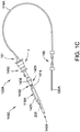
- Figure 1C is a schematic view of another embodiment of a catheter pump system.
- Figure 1C is similar to Figure 1B , except the motor 1 is miniaturized for insertion into the body.
- the motor 1 can be disposed proximal the impeller assembly 116A.
- the motor 1 can be generally similar to the motor assembly shown in Figure 2 , except the motor 1 is sized and shaped to be inserted into the patient's vasculature.
- One or more electrical lines may extend from the motor to the console outside the patient. The electrical lines can send signals for controlling the operation of the motor.
- Such embodiments allow a drive shaft coupled with the impeller and disposed within the catheter assembly 101 to be much shorter, e.g., shorter than the distance from the aortic valve to the aortic arch (about 5 cm or less).
- Various embodiments of the motor assembly 1 are disclosed herein, including embodiments having a rotor disposed within a stator assembly.
- waste fluid can pass through a housing in which the rotor is disposed to help cool the motor assembly 1.
- the housing in which the motor 1 of Figure 1C is disposed can be sealed from fluids (e.g., blood and/or saline) so as to isolate the electrical lines from the fluids.
- fluids e.g., blood and/or saline
- one or more seals can be provided to impede or prevent the flow of liquids into the housing.
- FIG. 1A illustrates one use of the catheter pump 100A.
- a distal portion of the pump 100A including a catheter assembly including the impeller assembly 116A is placed in the left ventricle (LV) of the heart to pump blood from the LV into the aorta.
- the pump 100A can be used in this way to treat a wide range of heart failure patient populations including, but not limited to, cardiogenic shock (such as acute myocardial infarction, acute decompensated heart failure, or postcardiotomy), myocarditis, and others.
- the pump can also be used for various other indications including to support a patient during a cardiac invention such as as a high-risk percutaneous coronary intervention (PCI) or ablation.
- PCI percutaneous coronary intervention
- One convenient manner of placement of the distal portion of the pump 100A in the heart is by percutaneous access and delivery using a modified Seldinger technique or other methods familiar to cardiologists. These approaches enable the pump 100A to be used in emergency medicine, a catheter lab and in other medical settings. Modifications can also enable the pump 100A to support the right side of the heart. Example modifications that could be used for right side support include providing delivery features and/or shaping a distal portion that is to be placed through at least one heart valve from the venous side, such as is discussed in US 6,544,216 ; US 7,070,555 ; and US 2012-0203056A1 , all of which are hereby incorporated by reference herein in their entirety for all purposes.
- the impeller assembly 116A (e.g., the impeller and cannula) can be expandable and collapsible. In the collapsed state, the distal end of the catheter pump 100A can be advanced to the heart, for example, through an artery. In the expanded state the impeller assembly 116A is able to pump blood at relatively high flow rates.
- the expandable cannula and impeller configuration allows for decoupling of the insertion size and flow rate, in other words, it allows for higher flow rates than would be possible through a lumen limited to the insertion size with all other things being equal.
- the impeller assembly 116A is illustrated in the expanded state.
- the collapsed state can be provided by advancing a distal end 170A of an elongate body 174A distally over the impeller assembly 116A to cause the impeller assembly 116A to collapse.
- This provides an outer profile throughout the catheter assembly and catheter pump 100A that is of small diameter during insertion, for example, to a catheter size of about 12.5 FR in various arrangements.
- the impeller assembly 116A is not expandable.
- the mechanical components rotatably supporting the impeller within the impeller assembly 116A permit relatively high rotational speeds while controlling heat and particle generation that can come with high speeds.
- the infusion system delivers a cooling and lubricating solution to the distal portion of the catheter pump 100A for these purposes.
- the space for delivery of this fluid is extremely limited. Some of the space is also used for return of the fluid as waste fluid. Providing secure connection and reliable routing of fluid into and out of the catheter pump 100A is critical and challenging in view of the small profile of the catheter assembly 101.
- the catheter pump 100A When activated, the catheter pump 100A can effectively support, restore and/or increase the flow of blood out of the heart and through the patient's vascular system.
- the pump 100A can be configured to produce a maximum flow rate (e.g. zero mm Hg backpressure) of greater than 4 Lpm, greater than 4.5 Lpm, greater than 5 Lpm, greater than 5.5 Lpm, greater than 6 Lpm, greater than 6.5 Lpm, greater than 7 Lpm, greater than 7.5 Lpm, greater than 8 Lpm, greater than 9 Lpm, or greater than 10 Lpm.
- a maximum flow rate e.g. zero mm Hg backpressure
- the pump 100A can be configured to produce an average flow rate at 62 mmHg of greater than 2 Lpm, greater than 2.5 Lpm, greater than 3 Lpm, greater than 3.5 Lpm, greater than 4 Lpm, greater than 4.25 Lpm, greater than 4.5 Lpm, greater than 5 Lpm, greater than 5.5 Lpm, greater than 6 Lpm, greater than 6.5 Lpm, greater than 7 Lpm, greater than 8 Lpm, or greater than 9 Lpm.
- a priming apparatus 1400 can be disposed over the impeller assembly 116A.
- the impeller assembly 116A can include an expandable cannula or housing and an impeller with one or more blades. As the impeller rotates, blood can be pumped proximally (or distally in some implementations) to function as a cardiac assist device.
- the pump is configured to be primed with fluid.
- a priming apparatus 1400 can be disposed over the impeller assembly 116A near the distal end portion 170A of the elongate body 174A.
- the priming apparatus 1400 can be used in connection with a procedure to expel air from the impeller assembly 116A, e.g., any air that is trapped within the housing or that remains within the elongate body 174A near the distal end 170A.
- the priming procedure may be performed before the pump is inserted into the patient's vascular system, so that air bubbles are not allowed to enter and/or injure the patient.
- the priming apparatus 1400 can include a primer housing 1401 configured to be disposed around both the elongate body 174A and the impeller assembly 116A.
- a sealing cap 1406 can be applied to the proximal end 1402 of the primer housing 1401 to substantially seal the priming apparatus 1400 for priming, i.e., so that air does not proximally enter the elongate body 174A and also so that priming fluid does not flow out of the proximal end of the housing 1401.
- the sealing cap 1406 can couple to the primer housing 1401 in any way known to a skilled artisan.
- the sealing cap 1406 is threaded onto the primer housing by way of a threaded connector 1405 located at the proximal end 1402 of the primer housing 1401.
- the sealing cap 1406 can include a sealing recess disposed at the distal end of the sealing cap 1406. The sealing recess can be configured to allow the elongate body 174A to pass through the sealing cap 1406.
- the catheter pump 100A can be removed from the priming apparatus 1400 before a percutaneous heart procedure is performed, e.g., before the pump 100A is activated to pump blood.
- the embodiments disclosed herein may be implemented such that the total time for infusing the system is minimized or reduced.
- the time to fully infuse the system can be about six minutes or less.
- the time to infuse can be about three minutes or less.
- the total time to infuse the system can be about 45 seconds or less. It should be appreciated that lower times to infuse can be advantageous for use with cardiovascular patients.
- the described pump is primed with fluid, one will appreciate from the description herein that the priming may be optional.
- the pump can be prepared such that all air is removed before it is packaged. In another example, air is removed by placing the pump under vacuum.
- a fluid supply line 6 can fluidly couple with the console 122 to supply saline or other fluid to the catheter pump 100A.
- the saline or other fluid can pass through an internal lumen of the internal catheter body 120A and can provide lubrication to the impeller assembly 116A and/or chemicals to the patient.
- the supplied fluid e.g., saline, dextrose, glucose solution, or infusate
- the fluid is supplied to the patient at a flow rate in a range of 15 mL/hr to 50 mL/hr, or more particularly, in a range of 20 mL/hr to 40 mL/hr, or more particularly, in a range of 25 mL/hr to 35 mL/hr.
- One or more electrical conduits 124 can provide electrical communication between the console 122 and the motor assembly 1.
- a controller within the console 122 can control the operation of the motor assembly 1 during use.
- Fluid e.g., saline
- the fluid can be provided from outside the patient (e.g., by way of one or more supply bags) to the pump through a supply lumen in the catheter body.
- the fluid can return to the motor assembly 1 by way of a lumen (e.g., a central or interior lumen) of the catheter body.
- a waste line 7 can extend from the motor assembly 1 to a waste reservoir 126. Waste fluid from the catheter pump 100A can pass through the motor assembly 1 and out to the reservoir 126 by way of the waste line 7.
- the waste fluid flows to the motor assembly 1 and the reservoir 126 at a flow rate which is lower than that at which the fluid is supplied to the patient.
- some of the supplied fluid may flow out of the catheter body 120A and into the patient by way of one or more bearings.
- the waste fluid (e.g., a portion of the fluid which passes proximally back through the motor from the patient) may flow through the motor assembly 1 at any suitable flow rate, e.g., at a flow rate in a range of 5 mL/hr to 20 mL/hr, or more particularly, in a range of 10 mL/hr to 15 mL/hr.
- the pump and motor be configured to operate without fluid flushing.
- One purpose of the fluid supply is to cool the motor.
- a micromotor dimensioned and configured to be inserted percutaneously, there may not be a need for fluid cooling because the motor heat will be dissipated by the body.
- Access can be provided to a proximal end of the catheter assembly 101 of the catheter pump 100A prior to or during use.
- the catheter assembly 101 is delivered over a guidewire 235.
- the guidewire 235 may be conveniently extended through the entire length of the catheter assembly 101 of the catheter pump 100A and out of a proximal end 1455 of the catheter assembly 101.
- the connection between the motor assembly 1 and the catheter assembly 101 is configured to be permanent, such that the catheter pump, the motor housing and the motor are disposable components.
- the coupling between the motor housing and the catheter assembly 101 is disengageable, such that the motor and motor housing can be decoupled from the catheter assembly 101 after use.
- the catheter assembly 101 distal of the motor can be disposable, and the motor and motor housing can be re-usable.
- Figure 1B illustrates the guidewire 235 extending from a proximal guidewire opening 237 in the motor assembly 1.
- a clinician may insert the guidewire 235 through the patient's vascular system to the heart to prepare a path for the impeller assembly 116A to the heart.
- the catheter pump 100A can include a guidewire guide tube 20 (see Figure 3 ) passing through a central internal lumen of the catheter pump 100A from the proximal guidewire opening 237.
- the guidewire guide tube 20 can be pre-installed in the catheter pump 100A to provide the clinician with a preformed pathway along which to insert the guidewire 235.
- the guidewire 235 is placed into a peripheral blood vessel, and along the path between that blood vessel and the heart and into a heart chamber, e.g., into the left ventricle. Thereafter, a distal end opening of the catheter pump 100A and guidewire guide tube 20 can be advanced over the proximal end of the guidewire 235 to enable delivery of the catheter pump 100A. After the proximal end of the guidewire 235 is urged proximally within the catheter pump 100A and emerges from the guidewire opening 237 and/or guidewire guide tube 20, the catheter pump 100A can be advanced into the patient. In one method, the guidewire guide tube 20 is withdrawn proximally while holding the catheter pump 100A.
- the clinician can insert the guidewire 235 through the proximal guidewire opening 237 and urge the guidewire 235 along the guidewire guide tube.
- the clinician can continue urging the guidewire 235 through the patient's vascular system until the distal end of the guidewire 235 is positioned in the desired position, e.g., in a chamber of the patient's heart, a major blood vessel or other source of blood.
- a proximal end portion of the guidewire 235 can extend from the proximal guidewire opening 237.
- catheter pump 100A is configured to be inserted using a modified Seldinger technique.
- the pump may be configured with a lumen therethrough for receiving a guidewire.
- the guidewire is threaded through the pump without a guidewire guide tube.
- Other configurations may be employed for loading the pump onto a guidewire and/or moving the pump to the target location in the body. Examples of similar techniques are described in U.S. Pat. No. 7,022,100 and U.S. Pub. No. 2005/0113631 , the entire contents of which patent and publication are incorporated herein for all purposes.
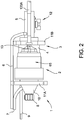
- FIGs 2 and 3 further illustrate aspects of embodiments of the motor assembly 1 shown in Figure 1B .
- the motor assembly 1 can include a stator assembly 2 ( Figs. 2-3 ) and a rotor 15 disposed radially within the stator assembly 2 ( Fig. 3 ).
- the motor assembly 1 also includes a flow diverter 3, which can be configured as a manifold for directing fluid through one or more passages in the catheter pump 100A. In some cases, the flow diverter 3 is at least partially disposed radially between the stator assembly 2 and the rotor 15 ( Figs. 2-3 ).
- the flow diverter 3 can be fluidly sealed about the rotor 15 and a proximal portion 56 of the catheter body 120A.
- the seal prevents leakage and also can prevent the fluid from contacting the stator assembly 2.
- the flow diverter 3 can include a distal chamber 5 within which the proximal portion 56 of the catheter body 120A is disposed and a rotor chamber 4 within which the rotor 15 is disposed.
- the distal chamber 5 is fluidly connected with the catheter.
- the rotor chamber 4 is fluidly connected with the waste line 7.
- the flow diverter 3 can also have a proximal chamber 10 in some embodiments. Where provided, the distal chamber 5, rotor chamber 4, and proximal chamber 10 can be in fluid communication within the flow diverter 3.
- One or more flanges 11A, 11B can mechanically couple the flow diverter 3 to an external housing (not shown).
- the rotor 15 and stator assembly 2 are configured as or are components of a frameless-style motor for driving the impeller assembly 116A at the distal end of the pump 100A.
- the stator assembly 2 can comprise a stator and a plurality of conductive windings producing a controlled magnetic field. The windings can be wrapped about or in a stationary portion 65 of the stator assembly 2.
- the rotor 15 can comprise a magnetic material, e.g., can include one or more permanent magnets.
- the rotor 15 can comprise a multi-pole magnet, e.g., a four-pole or six-pole magnet.
- the console 122 can provide electrical power (e.g., 24V) to the stator assembly 2 to drive the motor assembly 1.
- One or more leads 9 can electrically communicate with the stator assembly 2, e.g., with one or more Hall sensors used to detect the speed and/or position of the motor. In other embodiments, other sensors (e.g ., optical sensors) can be used to measure motor speed.
- the rotor 15 can be secured to an output shaft 13 (which can comprise a hollow shaft with a central lumen) such that rotation of the rotor 15 causes the output shaft 13 to rotate.
- Figure 4A shows that the output shaft 13 (which is secured to the rotor 15) can be mechanically coupled with the proximal end portion of a drive shaft 16.
- the drive shaft 16 extends distally through an internal lumen of the catheter body 120A.
- a distal end portion of the drive shaft 16 is mechanically connected with the impeller.
- rotation of the rotor 15 causes the output shaft 13 to rotate, which, in turn, causes the drive shaft 16 and the impeller to rotate.
- Figure 4A also shows that a lumen 55 can extend through the output shaft 13 and the rotor 15.
- the lumen 55 is coupled with a lumen of the catheter body 120A such that the guidewire guide tube 20 can extend through the lumen 55 within the rotor 15 and into the lumen of the catheter body 120A.
- the drive shaft 16 comprises a braided shaft having an internal lumen.
- the braided drive shaft 16 or cable can be permeable to liquid such that supply fluid or waste fluid can flow from outside the drive shaft 16 to within the internal lumen of the drive shaft 16 (and vice versa).
- Figure 4A shows the tube end cap 8 welded or otherwise secured to a proximal end portion of the guide tube 20.
- the cap 8 can be removably engaged (e.g., screwed or otherwise removably locked) over a female receiver 71 that is secured in a proximal end of the proximal chamber 10.
- the proximal end of the female receiver 71 can be disposed in a counterbore of the cap 8, while the guide tube 20 extends through the central opening of the cap 8.
- one or more tabs of the receiver 71 can be rotated such that the tab(s) slide under a corresponding tab in the counterbore of the cap 8.
- FIG. 7 shows one embodiment of the cap 8 and of the female receiver 71 that can be coupled with the guide tube 20 (not shown).
- the cap 8 can be fixed to the guide tube 20; in other embodiments, the receiver 71 can be fixed to the guide tube 20.
- Engaging the cap 8 to the receiver 71 can advantageously prevent the guide tube 20 from accidentally being removed from or slid within the catheter pump 100A, e.g., if the patient or clinician impacts the cap 8.
- the clinician can disengage the cap 8 from the receiver 71 and can pull the guide tube 20 from the catheter pump 100A, for example, by pulling proximally on the end cap 8.
- a resealable septum 72 e.g., a resealable closure member
- the septum 72 will naturally reseal the pathway proximally from the motor assembly 1 such that fluid does not exit the assembly 1.
- cap 8 is locked and will not be dislodged without rotating and unlocking cap 8 from receiver 71. Otherwise, the cap 8 can slide axially if it is inadvertently bumped by the patient or clinician. This potentially results in the guide tube 20 being pulled out from the distal-most end of the impeller assembly 116A, and because the guide tube cannot be re-inserted, the clinician either has to use the catheter pump 100A without a guide or get a new pump.
- an external surface of an external housing of the motor assembly 1 may be kept at or below this temperature.
- regulatory guidelines can require that no part in contact with skin exceed 40°C.
- various strategies for heat management are employed by the inventions described herein.
- cooling refers to transferring away or dissipating heat, and in certain respects, cooling is used interchangeably with removing heat. In some embodiments, however, the fluids passing through or around the motor assembly 1 may not be utilized for cooling purposes.
- Various components of the motor assembly 1 generate heat.
- moving parts within the motor assembly 1 e.g., the rotating output shaft 13 and/or drive shaft 16
- heat can be generated by the electrical current flowing through the stator assembly 2 and/or by induction heating caused by conductive components inside a rotating magnetic field.
- friction between the bearings 18A, 18B and the output shaft 13 and/or friction between the drive shaft 16 and the inner wall of catheter body 120A may also generate undesirable heat in the motor assembly. Inadequate cooling can result in temperature increases of the motor assembly 1, which can present patient discomfort, health risks, or performance losses.
- various embodiments disclosed herein can advantageously transfer away generated heat and cool the motor assembly 1 such that the operating temperature of the assembly 1 is sufficiently low to avoid such complexities of use or operation and/or other components of the system.
- various heat transfer components can be used to move heat away from thermal generation sources and away from the patient.
- Various aspects of the illustrated device herein are designed to reduce the risk of hot spots, reduce the risk of heat spikes, and/or improve heat dissipation to the environment and away from the patient.
- the catheter pump makes use of the fluid supply system already embedded in the pump to cool the motor assembly 1 and housing.
- heat absorbing capacity of fluid flowing through the flow diverter 3 is used to cool the motor assembly 1.
- the supply line 6 can supply fluid 35 from a source (e.g., a fluid bag) to an outer lumen 57 of the catheter body 120A.
- the supplied fluid 35 can travel distally toward the impeller assembly 116A to lubricate rotating components in the catheter assembly 101 and/or supply fluid to the patient.
- a seal 19 e.g., an o-ring
- backflow is flow of fluid 35 proximally into the distal chamber 5 rather than distally within the lumen 57. Such flow is to be prevented to ensure that the fluid 35 is initially exposed to moving parts in a distal portion of the catheter assembly 101 to lubricate and cool such distal components.
- Fluid from the catheter pump 100A can flow proximally through an inner lumen 58 of the catheter body 120A.
- some or all of the supplied fluid 35 can flow within the drive shaft 16 and/or around the periphery of the drive shaft 16.
- some or all of the supplied fluid 35 can flow in a space disposed radially between the drive shaft 16 and the catheter body 120A.
- the proximally-flowing fluid can flow along a flow pathway which removes heat from the motor assembly 1. As shown in Figure 4A , the proximally-flowing fluid (or other cooling fluid) can flow into the rotor chamber 4 of the flow diverter 3.
- a first portion 17A of the waste fluid can pass proximally through the motor assembly 1 about a periphery of the rotor 15, e.g., in a gap between the rotor 15 and a wall of the flow diverter 3.
- a second portion 17B of the waste fluid can pass proximally through the motor assembly 1 through the lumen 55 of the output shaft 13.
- the fluid portions 17A, 17B can pass from the rotor chamber 4 into the proximal chamber 10 of the flow diverter 3, where the fluid 17A, 17B can flow out to a reservoir (not shown) by way of line 7.
- the embodiment of Figure 4A can advantageously convey heat from the heat generating components (e.g ., rotor 15 and stator assembly 2) into the fluid 35 or other cooling fluid and to the reservoir 126 by way of the waste line 7.
- the first portion 17A of the fluid that passes about the periphery of the rotor 15 can direct heat radially outward from the rotor 15 and other components of the flow diverter 3.
- the first portion 17A of the fluid that passes about the periphery of the rotor 15 can direct heat inward from the stator assembly 2 and other components outside the flow diverter 3.
- the second portion 17B of the waste fluid can draw heat radially inward, e.g., radially inward from the rotor 15 and other components of the flow diverter 3.
- the temperature of the motor housing can be reduced or maintained at a suitable operational temperature for the medical staff, the patient and/or for the catheter pump system.
- a gap between the stator assembly and the external motor housing e.g., the outer shell or housing surrounding the motor assembly
- air which has the added benefit of being readily available and a good, natural insulator
- inert gas which has the added benefit of being readily available and a good, natural insulator
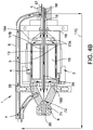
- Figure 4B is a side cross-sectional view of a motor assembly 1, according to another embodiment.
- components numbered similar to those in Figure 4A represent the same or similar components and functionalities.
- a first portion 17A of the fluid can pass proximally through the motor assembly 1 about a periphery of the rotor 15, e.g., in a gap between the rotor 15 and a wall of the flow diverter 3.
- a second portion 17B of the fluid can pass proximally through the motor assembly 1 through the lumen 55 of the output shaft 13.
- the third portion 17C of the proximally-flowing fluid can be more than, less than, or about the same in volume as the combined volume of the first and second fluid portions 17A, 17B.
- the third portion 17C can be transported by a conduit to a heat exchanger to further cool the motor assembly 1.
- the third fluid portion 17C can be conveyed to coiled tubing or a tubular sleeve disposed about the stator assembly 2, as shown in various embodiments of the following concurrently filed application: Application No. 15/003,682 , entitled "MOTOR ASSEMBLY WITH HEAT EXCHANGER FOR CATHETER PUMP," which is expressly incorporated by reference herein in its entirety and for all purposes.
- the fluid may flow back proximally through the flow diverter at rate such that the combined flow rate of the first and second portions 17A, 17B is in a range of 5 mL/hr to 20 mL/hr, or more particularly, in a range of 10 mL/hr to 15 mL/hr.
- the proximally-flowing fluid is diverted around the flow diverter 3 and other components of the motor along the second fluid pathway as the third fluid portion 17C.
- the amount of the fluid portion 17C diverted around the motor assembly 1 can be any suitable amount so as to maintain an adequate external temperature of the motor assembly 1.
- the third fluid portion 17C represents a relatively small volume of fluid diverted from the inner lumen 58.
- the third fluid portion 17C flows around the motor assembly 1 at a flow rate in a range of 1 mL/hr to 30 mL/hr.
- the third fluid portion 17C may have a flow rate in a range of 5.5 mL/hr to 12 mL/hr, in a range of 5.5 mL/hr to 10 mL/hr, in a range of 5.5 mL/hr to 8 mL/hr, in a range of 5.5 mL/hr to 7 mL/hr, in a range of 10 mL/hr to 14 mL/hr, or in a range of 8 mL/hr to 12 mL/hr.
- diverting some of the proximally-flowing fluid around the motor assembly 1 can improve the transfer of heat away from the motor assembly 1, for example, in situations in which the first and second fluid portions 17A, 17B become too hot.
- the console 122 can be configured to change the amount of the third fluid portion 17C flowing along the second fluid pathway before and/or during a treatment procedure to adjust the volume of fluid that is diverted from the inner lumen 58 around the motor assembly 1.
- the console 122 can send instructions to a pump (such as a peristaltic pump) to adjust the flow rate of fluid shunted or bypassed around the motor assembly 1.
- a pump such as a peristaltic pump
- bypassed and bypassed
- a common pump is applied to all three fluid portions 17A-17C. In other embodiments, one pump is applied to draw the first and second fluid portions 17A, 17B, and a separate pump is applied to draw the third fluid portion 17C.
- all or substantially all the fluid flowing proximally through the inner lumen 58 is shunted around the motor assembly 1 along the second fluid pathway.
- the shunted third fluid portion 17C can be diverted to a waste reservoir and/or to a heat exchanger disposed about the stator assembly 2, as explained above.
- all (100%) or substantially all (i.e., between 90% and 100%) of the proximally-flowing fluid does not flow within the motor assembly 1 (e.g., within the flow diverter 3), but is instead diverted around the motor assembly 1.
- the motor assembly 1 may be adequately cooled without the fluid portions 17A, 17B flowing proximally through the flow diverter 3.
- the fluid flowing proximally through the inner lumen 58 may also provide sufficient pressure so as to prevent air or other gases from passing distally through the catheter body 120A to the patient.
- the embodiments disclosed in Figures 1A-4B can adequately remove heat from the motor assembly 1 without requiring the use of external cooling fins exposed to the outside environs. That is, the thermal performance of the heat removal systems disclosed in Figures 2-4B can adequately reduce the temperature of the outer surface of the motor housing without using cooling fins exposed outside of the motor housing ( e.g ., outside of an exterior surface of the motor assembly 1) to the ambient environment. Rather, the heat removal systems may be disposed entirely within the motor housing, e.g., within the housing which encloses the rotor and stator. For example, in some embodiments, the systems disclosed in Figures 1A-4B can ensure that the temperature of the exterior surface of the motor assembly 1 is not more than about 40 °C.
- the systems disclosed in Figures 1A-4B can ensure that the temperature of the exterior surface of the motor assembly 1 is in a range of 15 °C to 42 °C, or more particularly in a range of 20 °C to 42 °C, in a range of 20 °C to 40 °C, in a range of 20 °C to 35 °C, or in a range of 20 °C to 30 °C, without requiring the use of external cooling fins exposed outside the motor housing.
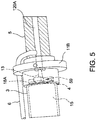
- Figure 5 is a schematic perspective view of an interface between the distal chamber 5 and the rotor chamber 4 of the flow diverter 3, with the stator assembly 2 hidden for ease of illustration.
- Figure 5 shows the output shaft 13 coupled with a proximal portion of the drive shaft 16 through an aperture in the flange 11B.
- the journal bearings 18A ( Figs. 3 and 5 ) and 18B ( Fig. 3 ) can be provided on opposite axial sides of the rotor 15 to help maintain the rotor 15 in radial alignment with the rotor chamber 4 and/or in axial alignment with the stator assembly 2. Improving radial alignment of the rotor 15 and output shaft 13 relative to the rotor chamber 4 can reduce or eliminate eccentricity during rotation, which can reduce vibrations.
- the passages 59 are defined at least in part by a cross-shaped structure of the bearings 18A, 18B, but other variations for the passages 59 may be suitable.
- the bearings 18A, 18B can form radially-extending arms with one or more gaps disposed between the arms. Such gaps can be enclosed peripherally by a housing enclosing the stator assembly 2.
- one or more openings can be provided through the bearings 18A, 18B to define the passages.
- Figures 6A and 6B show one embodiment of an interface 22 between the output shaft 13 and the drive shaft 16.
- the interface 22 can comprise a connection between a distal portion of the output shaft 13 and a proximal portion of the drive shaft 16.
- the distal portion of the output shaft 13 can comprise a radially-inward taper and one or more holes 61 formed through the output shaft 13.
- the proximal portion of the drive shaft 16 can be inserted within the lumen 55 of the output shaft 13 such that the lumen 55 and the inner lumen 58 of the catheter body 120A form a continuous passage. This passage can be used to advance the guidewire guide tube 20, sensors, and other instruments, or to provide fluid communication for cooling fluid or medications.
- Cooling fluid can flow proximally from the inner lumen 58 of the catheter body 120A and the first portion 17A of the fluid can pass outwardly about the periphery of the rotor 15.
- the second portion 17B of the fluid can pass through the lumen 55 of the output shaft 13.
- a sleeve 21 can be disposed about the proximal portion of the catheter body 120A, and the seal 19 can be provided about the sleeve 21 to seal the distal chamber 5 from the rotor chamber 4.
- the output shaft 13 is permanently coupled with, e.g., laser welded to the drive shaft 16.
- a welding machine can access the interface 22 by way of the holes 61 formed in the output shaft 13 to weld the output shaft 13 to the drive shaft 16.
- the output shaft 13 can be secured to the drive shaft 16 in other ways, e.g., by friction or interference fit, by adhesives, by mechanical fasteners, etc.
- the motor assembly 1 shown in Figures 1B-1C can be sealed from the fluids (e.g., saline and/or bodily fluids) that pass proximally through the catheter assembly.
- the proximally-flowing fluid may flow from the catheter body 120A through a chamber near the motor assembly 1.
- the proximally-flowing fluid may flow through a chamber in which a portion of the motor assembly (e.g ., the rotor) is disposed, such as the flow diverter 3.
- the catheter pump system can include a shaft assembly 302 and an impeller coupled with a distal portion of the shaft assembly 302.
- the catheter pump system can include a motor assembly 1 which imparts rotation on the impeller through the shaft assembly 302.
- the motor assembly 1 can comprise a motor 300 (e.g., an electric motor such as a direct drive electric motor) which rotates the shaft assembly 302.
- a direct drive motor can comprise a motor that lacks a gear reduction and/or a clutch.
- a fluid pathway can convey fluid (e.g., waste fluid) proximally during operation of the catheter pump system.
- a seal 303 can be disposed between the motor assembly 1 and the impeller to impede or prevent proximally-flowing fluids from entering the motor assembly 1 at least about an outer periphery 308 of the shaft assembly 302.
- the seal 303 can comprise an opening 309 through which a portion of the shaft assembly 302 extends.
- a lumen can comprise a motor lumen extending through at least the motor 300. The lumen can pass through the catheter pump system from a distal end of the catheter pump to a proximal end of the catheter pump system.
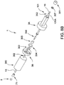
- FIGS 8A-8E an example of a motor assembly 1 is disclosed, according to some embodiments.
- the motor assembly 1 of Figures 8A-8E may be used in combination with any suitable features disclosed above in connection with Figures 1A-7 .
- like reference numerals refer to components that are the same as or generally similar to the components shown in Figures 1A-7 .
- the motor assembly 1 can comprise a motor 300.
- the motor 300 can comprise a direct drive electrical motor.
- the motor can be a direct current (DC) motor.
- an end cap 8 and receiver 71 can be provided at the proximal end of the motor assembly 1 to provide access to an internal lumen within the assembly 1.
- the end cap comprises a resealable material, e.g., to provide resealable access for a guidewire guide tube and/or guidewire.
- any suitable type of chamber may be disposed distal the motor assembly 1 to direct fluids into and/or out of the catheter assembly.
- the flow diverter 3 can comprise a distal flow diverter portion 3A and a proximal flow diverter portion 3B.
- the retaining cap 301 can couple with the distal flow diverter portion 3A with a washer 307 disposed therebetween.
- the retaining cap 301 and washer 307 can be disposed over the catheter body 120A.
- the flow diverter 3 can comprise a chamber in which various components are disposed.
- a motor coupling 305, a motor adapter 306, a gasket 304, and a seal 303 can be disposed in the chamber of the flow diverter 3.
- the motor coupling 305 can connect to a distal end portion of the motor output shaft 13, and can connect to a proximal portion of the motor adapter 306.
- the motor coupling 305 can comprise a first opening 311A sized and shaped to receive the proximal portion of the motor adapter 306 therein, and a second opening 311B sized and shaped to receive the distal end portion of the motor output shaft 13.
- at least one of the openings 311A, 311B can comprise a polygonal opening, e.g., a rectangular or square opening with at least one flat surface or edge.
- the first opening 311A can comprise a polygonal opening
- the second opening 311B can comprise a rounded opening.
- fluids can flow proximally through the catheter pump system during operation of the impeller.
- a supply fluid pathway 335 can direct fluid (e.g., saline, infusate, etc.) distally through a lumen disposed within, but in some embodiments located off-center relative to a central longitudinal axis of, the catheter body 120A to provide a lubricant, e.g., saline, to the impeller.
- a return fluid pathway 317 can be provided along the inner lumen 358 of the catheter body 120A such that proximally flowing fluid flows towards the motor assembly 1 from a distal portion of the device adjacent to the impeller.
- the return fluid pathway 317 can flow within and/or around the drive shaft 16, which can be disposed inside the inner lumen 358.
- the seal 303 and the gasket 304 can be disposed in the chamber of the flow diverter 3 to prevent or impede fluids from damaging sensitive components of the motor.
- some or all of the fluid conveyed along the returning fluid pathway 317 exits the flow diverter 3 by way of a first return pathway 317A.
- the first return pathway 317A can be in fluid communication with a waste line to convey fluid flowing therein to and along the waste line (such as waste line 7 described above) to a reservoir.
- the first return pathway 317A may comprise a conduit that directs a portion of the fluid to bypass the motor assembly 1.
- some of the returning fluid can pass within the lumen 355 of the motor output shaft 13.
- the returning fluid 317 can flow through the inner lumen 358 of the catheter body 120A, which can fluidly communicate with the lumen 355 of the motor output shaft 13.
- Fluid conveyed in the returning fluid pathway 317 can flow proximally within and/or around the drive shaft 16 (which can be disposed inside the inner lumen 358 of the catheter body 120A), through the motor adapter 306, the motor coupler 305, the seal 303, and the proximal flow diverter portion 3B, and into the lumen 355 of the motor output shaft 13.
- no or little fluid may flow through the lumen 355 of the output shaft 13.
- the shaft assembly 302 (e.g., including the motor output shaft 13) can extend through at least a portion of the motor 300, through the proximal flow diverter portion 3B, through an opening 309 of the seal 303, and into the motor coupling 305.
- the shaft assembly 302 (e.g., including the drive shaft 16) can further extend from the motor adapter 306 distally to the impeller assembly.
- the shaft assembly 302 and a lumen thereof can extend through the seal 303.
- a guidewire guide tube (not shown in Figures 8A-8E ) may be disposed in a lumen which comprises the lumen 355 of the output shaft 13 and the inner lumen 358 of the catheter body 120A.
- the guidewire guide tube may extend through a lumen which extends between the distal end of the catheter pump system and the proximal end of the catheter pump system ( i.e., proximally out the end cap 8).
- the clinician may insert a guidewire through the guidewire guide tube and may advance the impeller assembly over the guidewire guide tube to a treatment location, as explained above.
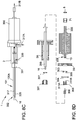
- Figure 8E is a schematic side sectional view of the motor assembly 1 shown in Figures 8A-8D .
- Figure 8F is a magnified schematic side sectional view of the motor assembly shown in Figure 8E .
- the shaft assembly 302 may extend from the motor 300 into the chamber of the flow diverter 3 through the opening 309 in the seal 303.
- the shaft assembly 302 (which may comprise the drive shaft 16 and the motor output shaft 13) may rotate relative to the proximal flow diverter portion 3B and the seal 303.
- the seal 303 can comprise a lip seal having a flange 310 which extends towards and contacts the outer periphery 308 of the shaft assembly 302 (e.g., the output shaft 13 in some embodiments).
- the seal 303 can be disposed about the shaft assembly 302 and can be biased radially inward to bear against the outer periphery 308 of the shaft assembly 302 to enhance the fluid sealing effect of the seal 303.
- a biasing member 345 e.g., a spring or other biasing member such as a canted coil spring
- the seal has a cupped or canted shape.
- the flange 310 can also define a recess into which some fluid being conveyed with the returning fluid pathway 317 can flow.
- the axial fluid flow component of the fluid that is conveyed in the returning fluid pathway 317 i.e., the component of the fluid which flows generally parallel to the shaft assembly 302
- the axial fluid flow component of the fluid that is conveyed in the returning fluid pathway 317 can press against the flange 310 to convert the axial fluid forces (i.e., the force of the proximally-flowing fluid along a direction parallel to the shaft assembly 302) to radially inward pressure P to further bear against the outer periphery 308 of the shaft assembly 302.
- Figure 8G is a schematic side sectional view of the seal 303 shown in Figures 8A-8F .
- a second seal 303A (which may be similar to the seal 303) may be disposed adjacent and proximal the proximal flow diverter portion 3B, which may act as a barrier between the motor 300 and the chamber (which may be defined by the flow diverter in some arrangements).
- the second seal 303A may also include an opening 309A through which a portion of the shaft assembly 302 may extend.
- the second seal 303A may be positioned between the flow diverter portion 3B and the motor 300. As shown, the seal 303 may be disposed adjacent and distal the proximal flow diverter portion 3B.
- the second seal 303A may be positioned between the flow diverter portion 3B and a distal portion of the catheter body 120A.
- the proximal flow diverter portion 3B can act as a fluid barrier between the motor assembly 1 and a majority of the proximally-flowing fluid.
- the second seal 303A is illustrated in Figure 8G , in various arrangements, the second seal 303A may not be provided.
- the seal 303 may be disposed in the chamber of the flow diverter 3 (or other suitable structure which defines a chamber), and the second seal 303A may be disposed outside the chamber of the flow diverter 3.
- the shaft assembly 302 may extend from the motor 300 into the chamber of the flow diverter 3 through the opening 309 in the seal 303.
- the shaft assembly 302 (which may comprise the drive shaft 16 and the motor output shaft 13) may rotate relative to the proximal flow diverter portion 3B and the seals 303, 303A.
- Figures 9A-9B illustrate another embodiment of a motor assembly 1 with a seal 303 that prevents or impedes proximally-flowing fluid from entering the motor assembly 1 at least about an outer periphery 308 of a shaft assembly 302.
- the motor assembly 1 is similar to the motor assembly 1 shown and described above in connection with Figures 2-7 , except as noted herein.
- the motor assembly of Figures 9A-9B can comprise a rotor 15 disposed inside a rotor chamber 4.
- a stator assembly 2 can be disposed outside the rotor chamber 4 about the rotor 15 and rotor chamber 4.
- the windings of the stator assembly 2 can be energized to cause the rotor 15 to rotate.
- Rotation of the rotor 15 can cause the output shaft 13 to impart rotation to the drive shaft 16 and the impeller at the distal portion of the system.
- a flow diverter 3 can be disposed distal the motor assembly 1. As explained above, the flow diverter 3 can route fluid distally to the impeller assembly and proximally to a waste reservoir.
- the rotor 15, rotor chamber 4, and stator assembly 2 may be disposed proximal and outside the flow diverter 3.
- all or a portion of the fluid flowing proximally through the catheter body 120A may be shunted around the motor assembly 1, and the motor assembly 1 can be sealed such that little or no fluid enters the motor assembly 1, e.g., little or no fluid enters the rotor chamber 4.
- a seal 303 can be provided between the rotor chamber 4 and the flow diverter 3 (which may act as a barrier between the rotor chamber 4 and the proximally-flowing fluid.
- the pump system is configured to selectively shunt fluid around the motor assembly.
- the seal 303 used in connection with Figures 9A-9B can be similar to the seals 303, 303A described in relation to Figures 8A-8G .
- the seal 303 can be disposed about the shaft assembly 302 and can be biased radially inward to bear against the outer periphery 308 of the shaft assembly 302 to enhance the fluid sealing effect of the seal 303.
- a second seal (such as seal 303A) can be disposed opposite the barrier, e.g., on the distal side of the barrier defined by the flow diverter 3.
Landscapes
- Health & Medical Sciences (AREA)
- Heart & Thoracic Surgery (AREA)
- Engineering & Computer Science (AREA)
- Life Sciences & Earth Sciences (AREA)
- Veterinary Medicine (AREA)
- Public Health (AREA)
- Biomedical Technology (AREA)
- Hematology (AREA)
- Anesthesiology (AREA)
- Animal Behavior & Ethology (AREA)
- General Health & Medical Sciences (AREA)
- Mechanical Engineering (AREA)
- Cardiology (AREA)
- Vascular Medicine (AREA)
- Biophysics (AREA)
- Pulmonology (AREA)
- External Artificial Organs (AREA)
- Transplantation (AREA)
Applications Claiming Priority (3)
| Application Number | Priority Date | Filing Date | Title |
|---|---|---|---|
| US201662365215P | 2016-07-21 | 2016-07-21 | |
| EP17746274.4A EP3487549B1 (de) | 2016-07-21 | 2017-07-19 | Fluiddichtungen für katheterpumpenmotoranordnung |
| PCT/US2017/042803 WO2018017678A1 (en) | 2016-07-21 | 2017-07-19 | Fluid seals for catheter pump motor assembly |
Related Parent Applications (2)
| Application Number | Title | Priority Date | Filing Date |
|---|---|---|---|
| EP17746274.4A Division EP3487549B1 (de) | 2016-07-21 | 2017-07-19 | Fluiddichtungen für katheterpumpenmotoranordnung |
| EP17746274.4A Division-Into EP3487549B1 (de) | 2016-07-21 | 2017-07-19 | Fluiddichtungen für katheterpumpenmotoranordnung |
Publications (1)
| Publication Number | Publication Date |
|---|---|
| EP3808403A1 true EP3808403A1 (de) | 2021-04-21 |
Family
ID=59501567
Family Applications (3)
| Application Number | Title | Priority Date | Filing Date |
|---|---|---|---|
| EP20210773.6A Pending EP3804804A1 (de) | 2016-07-21 | 2017-07-19 | Fluiddichtungen für katheterpumpenmotoranordnung |
| EP20210775.1A Pending EP3808403A1 (de) | 2016-07-21 | 2017-07-19 | Fluiddichtungen für katheterpumpenmotoranordnung |
| EP17746274.4A Active EP3487549B1 (de) | 2016-07-21 | 2017-07-19 | Fluiddichtungen für katheterpumpenmotoranordnung |
Family Applications Before (1)
| Application Number | Title | Priority Date | Filing Date |
|---|---|---|---|
| EP20210773.6A Pending EP3804804A1 (de) | 2016-07-21 | 2017-07-19 | Fluiddichtungen für katheterpumpenmotoranordnung |
Family Applications After (1)
| Application Number | Title | Priority Date | Filing Date |
|---|---|---|---|
| EP17746274.4A Active EP3487549B1 (de) | 2016-07-21 | 2017-07-19 | Fluiddichtungen für katheterpumpenmotoranordnung |
Country Status (3)
| Country | Link |
|---|---|
| US (5) | US11160970B2 (de) |
| EP (3) | EP3804804A1 (de) |
| WO (1) | WO2018017678A1 (de) |
Families Citing this family (61)
| Publication number | Priority date | Publication date | Assignee | Title |
|---|---|---|---|---|
| CA2646277C (en) | 2006-03-23 | 2016-01-12 | The Penn State Research Foundation | Heart assist device with expandable impeller pump |
| US9446179B2 (en) | 2012-05-14 | 2016-09-20 | Thoratec Corporation | Distal bearing support |
| DE102013008159A1 (de) | 2012-05-14 | 2013-11-14 | Thoratec Corporation | Mantelsystem für Katheterpumpe |
| GB2504176A (en) | 2012-05-14 | 2014-01-22 | Thoratec Corp | Collapsible impeller for catheter pump |
| US9358329B2 (en) | 2012-07-03 | 2016-06-07 | Thoratec Corporation | Catheter pump |
| EP3834876B1 (de) | 2013-03-13 | 2022-09-14 | Tc1 Llc | Flüssigkeitsbehandlungssystem |
| US10583232B2 (en) | 2014-04-15 | 2020-03-10 | Tc1 Llc | Catheter pump with off-set motor position |
| US10363349B2 (en) | 2014-04-15 | 2019-07-30 | Tc1 Llp | Heart pump providing adjustable outflow |
| EP3804804A1 (de) * | 2016-07-21 | 2021-04-14 | Tc1 Llc | Fluiddichtungen für katheterpumpenmotoranordnung |
| EP4732889A2 (de) | 2017-06-07 | 2026-04-29 | Supira Medical, Inc. | Vorrichtungen, systeme und verfahren zur bewegung intravaskulärer flüssigkeiten |
| JP7319266B2 (ja) | 2017-11-13 | 2023-08-01 | シファメド・ホールディングス・エルエルシー | 血管内流体移動デバイス、システム、および使用方法 |
| DE102018201030B4 (de) | 2018-01-24 | 2025-10-16 | Kardion Gmbh | Magnetkuppelelement mit magnetischer Lagerungsfunktion |
| EP4085965A1 (de) | 2018-02-01 | 2022-11-09 | Shifamed Holdings, LLC | Intravaskuläre blutpumpen und verfahren zur verwendung und herstellung |
| EP3542837B1 (de) * | 2018-03-23 | 2020-09-02 | Abiomed Europe GmbH | Intravaskuläre blutpumpe |
| US11167121B2 (en) * | 2018-05-15 | 2021-11-09 | Cardiovascular Systems, Inc. | Intravascular pump with integrated isolated conductor(s) and methods thereof |
| DE102018207611A1 (de) | 2018-05-16 | 2019-11-21 | Kardion Gmbh | Rotorlagerungssystem |
| DE102018207575A1 (de) | 2018-05-16 | 2019-11-21 | Kardion Gmbh | Magnetische Stirndreh-Kupplung zur Übertragung von Drehmomenten |
| DE102018207594A1 (de) | 2018-05-16 | 2019-11-21 | Kardion Gmbh | Rotor, Magnetkupplungsvorrichtung, Elektromotor für ein Herzunterstützungssystem, Pumpeneinheit für ein Herzunterstützungssystem sowie Verfahren zum Herstellen eines Rotors |
| DE102018208555A1 (de) | 2018-05-30 | 2019-12-05 | Kardion Gmbh | Vorrichtung zum Verankern eines Herzunterstützungssystems in einem Blutgefäß, Verfahren zum Betreiben und Herstellverfahren zum Herstellen einer Vorrichtung und Herzunterstützungssystem |
| DE102018208537A1 (de) | 2018-05-30 | 2019-12-05 | Kardion Gmbh | Vorrichtung zum Anbinden eines Herzunterstützungssystems an eine Einführeinrichtung und Verfahren zum Herstellen einer Vorrichtung zum Anbinden eines Herzunterstützungssystems an eine Einführeinrichtung |
| DE102018208541A1 (de) | 2018-05-30 | 2019-12-05 | Kardion Gmbh | Axialpumpe für ein Herzunterstützungssystem und Verfahren zum Herstellen einer Axialpumpe für ein Herzunterstützungssystem |
| DE102018208549A1 (de) | 2018-05-30 | 2019-12-05 | Kardion Gmbh | Elektronikmodul für ein Herzunterstützungssystem und Verfahren zum Herstellen eines Elektronikmoduls für ein Herzunterstützungssystem |
| DE102018208564A1 (de) | 2018-05-30 | 2019-12-05 | Kardion Gmbh | Steuerbare Einführungshülse |
| DE102018208539A1 (de) | 2018-05-30 | 2019-12-05 | Kardion Gmbh | Motorgehäusemodul zum Abdichten eines Motorraums eines Motors eines Herzunterstützungssystems und Herzunterstützungssystem und Verfahren zum Montieren eines Herzunterstützungssystems |
| DE102018208538A1 (de) | 2018-05-30 | 2019-12-05 | Kardion Gmbh | Intravasale Blutpumpe und Verfahren zur Herstellung von elektrischen Leiterbahnen |
| DE102018208550A1 (de) | 2018-05-30 | 2019-12-05 | Kardion Gmbh | Leitungsvorrichtung zum Leiten eines Blutstroms für ein Herzunterstützungssystem, Herzunterstützungssystem und Verfahren zum Herstellen einer Leitungsvorrichtung |
| DE102018210058A1 (de) | 2018-06-21 | 2019-12-24 | Kardion Gmbh | Statorschaufelvorrichtung zur Strömungsführung eines aus einer Austrittsöffnung eines Herzunterstützungssystems ausströmenden Fluids, Herzunterstützungssystem mit Statorschaufelvorrichtung, Verfahren zum Betreiben einer Statorschaufelvorrichtung und Herstellverfahren |
| DE102018210076A1 (de) | 2018-06-21 | 2019-12-24 | Kardion Gmbh | Verfahren und Vorrichtung zum Erkennen eines Verschleißzustands eines Herzunterstützungssystems, Verfahren und Vorrichtung zum Betreiben eines Herzunterstützungssystems und Herzunterstützungssystem |
| DE102018211297A1 (de) | 2018-07-09 | 2020-01-09 | Kardion Gmbh | Herzunterstützungssystem und Verfahren zur Überwachung der Integrität einer Haltestruktur eines Herzunterstützungssystems |
| DE102018211328A1 (de) | 2018-07-10 | 2020-01-16 | Kardion Gmbh | Laufradgehäuse für ein implantierbares, vaskuläres Unterstützungssystem |
| DE102018211327A1 (de) | 2018-07-10 | 2020-01-16 | Kardion Gmbh | Laufrad für ein implantierbares, vaskuläres Unterstützungssystem |
| DE102018212153A1 (de) | 2018-07-20 | 2020-01-23 | Kardion Gmbh | Zulaufleitung für eine Pumpeneinheit eines Herzunterstützungssystems, Herzunterstützungssystem und Verfahren zum Herstellen einer Zulaufleitung für eine Pumpeneinheit eines Herzunterstützungssystems |
| US12161857B2 (en) | 2018-07-31 | 2024-12-10 | Shifamed Holdings, Llc | Intravascular blood pumps and methods of use |
| EP3833410B1 (de) | 2018-08-07 | 2025-10-08 | Kardion GmbH | Lagervorrichtung für ein herzunterstützungssystem und verfahren zum spülen eines zwischenraums in einer lagervorrichtung für ein herzunterstützungssystem |
| WO2020073047A1 (en) | 2018-10-05 | 2020-04-09 | Shifamed Holdings, Llc | Intravascular blood pumps and methods of use |
| NL2022660B1 (en) | 2019-03-01 | 2020-09-15 | Stichting Katholieke Univ | Heart Assist Device |
| EP3996797A4 (de) | 2019-07-12 | 2023-08-02 | Shifamed Holdings, LLC | Intravaskuläre blutpumpen und verfahren zur herstellung und verwendung |
| US11654275B2 (en) | 2019-07-22 | 2023-05-23 | Shifamed Holdings, Llc | Intravascular blood pumps with struts and methods of use and manufacture |
| CN110393846B (zh) * | 2019-08-01 | 2024-12-03 | 杨礼瑾 | 一种动力源可置于人体内的旋转传动导管 |
| EP4010046A4 (de) | 2019-08-07 | 2023-08-30 | Calomeni, Michael | Katheterblutpumpen und zusammenklappbare pumpengehäuse |
| US12121713B2 (en) | 2019-09-25 | 2024-10-22 | Shifamed Holdings, Llc | Catheter blood pumps and collapsible blood conduits |
| US12102815B2 (en) | 2019-09-25 | 2024-10-01 | Shifamed Holdings, Llc | Catheter blood pumps and collapsible pump housings |
| EP4034192B1 (de) | 2019-09-25 | 2025-12-24 | Supira Medical, Inc. | Intravaskuläre blutpumpensysteme und verfahren zur verwendung und steuerung davon |
| EP4072650A4 (de) | 2019-12-11 | 2024-01-10 | Shifamed Holdings, LLC | Absteigende aorten- und hohlvenenblutpumpen |
| WO2021127503A1 (en) | 2019-12-19 | 2021-06-24 | Shifamed Holdings, Llc | Intravascular blood pumps, motors, and fluid control |
| CN110743051B (zh) * | 2019-12-24 | 2020-05-15 | 丰凯医疗器械(上海)有限公司 | 用于医用介入器械的快接型磁传动装置 |
| DE102020102474A1 (de) | 2020-01-31 | 2021-08-05 | Kardion Gmbh | Pumpe zum Fördern eines Fluids und Verfahren zum Herstellen einer Pumpe |
| AU2021340802A1 (en) | 2020-09-14 | 2023-05-18 | Kardion Gmbh | Cardiovascular support pump having an impeller with a variable flow area |
| AU2021383931A1 (en) | 2020-11-20 | 2023-07-06 | Kardion Gmbh | Mechanical circulatory support system with guidewire aid |
| NL2028130B1 (en) | 2021-05-03 | 2022-11-10 | Cardiacbooster B V | Cardiac assist device with high frequency operation |
| US12551685B2 (en) | 2021-07-07 | 2026-02-17 | Fbr Medical, Inc. | Partially-deformable impeller and catheter blood pump incorporating same |
| CN113559408B (zh) * | 2021-07-09 | 2022-08-02 | 苏州心擎医疗技术有限公司 | 用于对心脏在发生功能衰竭时进行辅助的装置 |
| WO2023283751A1 (zh) * | 2021-07-12 | 2023-01-19 | 苏州心擎医疗技术有限公司 | 用于对心脏在发生功能衰竭时进行辅助的装置 |
| US20230096277A1 (en) * | 2021-09-30 | 2023-03-30 | Tc1 Llc | Catheter pump motor assembly including lubricated rotor chamber |
| US20230181893A1 (en) * | 2021-12-10 | 2023-06-15 | Tc1 Llc | Fluid seals for catheter pump motor assembly |
| CN114948107A (zh) * | 2022-06-20 | 2022-08-30 | 上海微创旋律医疗科技有限公司 | 旋磨装置 |
| CN115364337B (zh) * | 2022-09-28 | 2023-06-30 | 苏州心擎医疗技术有限公司 | 导管装置 |
| CN115970152A (zh) * | 2022-12-30 | 2023-04-18 | 丰凯利医疗器械(上海)有限公司 | 有源介入式医疗器械的电机组件 |
| CN116196549B (zh) * | 2023-02-14 | 2023-11-03 | 上海玮启医疗器械有限公司 | 心脏辅助系统驱动装置 |
| CN118718235A (zh) * | 2023-03-22 | 2024-10-01 | 丰凯利医疗器械(上海)有限公司 | 一种灌注装置 |
| CN121511114A (zh) * | 2023-04-13 | 2026-02-10 | 阿比奥梅德欧洲有限责任公司 | 血泵 |
Citations (34)
| Publication number | Priority date | Publication date | Assignee | Title |
|---|---|---|---|---|
| US4625712A (en) | 1983-09-28 | 1986-12-02 | Nimbus, Inc. | High-capacity intravascular blood pump utilizing percutaneous access |
| US4686982A (en) | 1985-06-19 | 1987-08-18 | John Nash | Spiral wire bearing for rotating wire drive catheter |
| US4747406A (en) | 1985-02-13 | 1988-05-31 | Intravascular Surgical Instruments, Inc. | Shaft driven, flexible intravascular recanalization catheter |
| WO1989005668A2 (en) * | 1987-12-07 | 1989-06-29 | Nimbus Medical, Inc. | Drive mechanism for powering intravascular blood pumps |
| US4944722A (en) | 1989-02-23 | 1990-07-31 | Nimbus Medical, Inc. | Percutaneous axial flow blood pump |
| US5921913A (en) * | 1996-04-03 | 1999-07-13 | Guidant Corporation | Statorless intravascular microaxial flow pump |
| US6176848B1 (en) | 1996-04-04 | 2001-01-23 | Impella Cardiotechnik Gmbh | Intravascular blood pump |
| WO2001017581A2 (en) * | 1999-09-03 | 2001-03-15 | A-Med Systems, Inc. | Guidable intravascular blood pump and related methods |
| US6544216B1 (en) | 1998-05-13 | 2003-04-08 | Impella Cardiotechnik Aktiengesellschaft | Intracardiac blood pump |
| US20050113631A1 (en) | 2003-11-12 | 2005-05-26 | Bolling Steven F. | Cannulae having a redirecting tip |
| US6926662B1 (en) | 1998-12-23 | 2005-08-09 | A-Med Systems, Inc. | Left and right side heart support |
| US7022100B1 (en) | 1999-09-03 | 2006-04-04 | A-Med Systems, Inc. | Guidable intravascular blood pump and related methods |
| US7070555B2 (en) | 2000-08-18 | 2006-07-04 | Impella Cardiosystems Ag | Intracardiac blood pump |
| US7393181B2 (en) | 2004-09-17 | 2008-07-01 | The Penn State Research Foundation | Expandable impeller pump |
| US7841976B2 (en) | 2006-03-23 | 2010-11-30 | Thoratec Corporation | Heart assist device with expandable impeller pump |
| US20110004046A1 (en) | 2009-07-01 | 2011-01-06 | The Penn State Research Foundation | Blood pump with expandable cannula |
| US7998054B2 (en) | 1997-10-09 | 2011-08-16 | Thoratec Corporation | Implantable heart assist system and method of applying same |
| US20110295345A1 (en) | 2010-05-28 | 2011-12-01 | Lockheed Martin Corporation | Implantable infrared nerve stimulation devices for peripheral and cranial nerve interfaces |
| US8157719B1 (en) | 2002-06-28 | 2012-04-17 | Advanced Cardiovascular Systems, Inc. | Devices and methods to perform minimally invasive surgeries |
| US20120172655A1 (en) | 2011-01-05 | 2012-07-05 | Campbell Robert L | Impeller housing for percutaneous heart pump |
| US20120178986A1 (en) | 2011-01-06 | 2012-07-12 | Campbell Robert L | Percutaneous heart pump |
| US20120178985A1 (en) | 2011-01-06 | 2012-07-12 | Walters Daniel A | Percutaneous heart pump |
| US20120203056A1 (en) | 2010-05-26 | 2012-08-09 | Corbett Scott C | Anatomic fit of a percutaneous vad for right heart support |
| US8489190B2 (en) | 2007-10-08 | 2013-07-16 | Ais Gmbh Aachen Innovative Solutions | Catheter device |
| US20130303970A1 (en) | 2012-05-14 | 2013-11-14 | Thoratec Corporation | Distal bearing support |
| US20130303969A1 (en) | 2012-05-14 | 2013-11-14 | Thoratec Corporation | Sheath system for catheter pump |
| US20130303830A1 (en) | 2012-05-14 | 2013-11-14 | Thoratec Corporation | Impeller for catheter pump |
| US8597170B2 (en) | 2011-01-05 | 2013-12-03 | Thoratec Corporation | Catheter pump |
| US20140012065A1 (en) | 2012-07-03 | 2014-01-09 | Thoratec Corporation | Catheter pump |
| WO2014008102A1 (en) * | 2012-07-03 | 2014-01-09 | Thoratec Corporation | Motor assembly for catheter pump |
| US20140031606A1 (en) | 2012-07-27 | 2014-01-30 | John Freddy Hansen | Thermal Management for Implantable Wireless Power Transfer Systems |
| US20140275725A1 (en) | 2013-03-13 | 2014-09-18 | Thoratec Corporation | Fluid handling system |
| WO2015055515A1 (de) * | 2013-10-14 | 2015-04-23 | Ecp Entwicklungsgesellschaft Mbh | Verfahren zum betrieb einer versorgungseinrichtung, die einen kanal mit einer flüssigkeit beaufschlagt, sowie versorgungseinrichtung, hohlkatheter und katheterpumpe |
| WO2016118777A1 (en) * | 2015-01-22 | 2016-07-28 | Thoratec Corporation | Reduced rotational mass motor assembly for catheter pump |
Family Cites Families (577)
| Publication number | Priority date | Publication date | Assignee | Title |
|---|---|---|---|---|
| US264134A (en) | 1882-09-12 | Steam-pump | ||
| US1902418A (en) | 1931-11-02 | 1933-03-21 | Jensen Salsbery Lab Inc | Surgical instrument |
| US2356659A (en) | 1941-11-24 | 1944-08-22 | Aguiar Clovis De Paiva | Nozzle for duodenal pump tubes |
| US2649052A (en) | 1947-04-17 | 1953-08-18 | Marine Products Company | Rotary pump or motor |
| US2684035A (en) | 1947-10-02 | 1954-07-20 | Philip G Kemp | Fluid pump |
| US2664050A (en) | 1949-03-02 | 1953-12-29 | Gen Motors Corp | Domestic appliance |
| US2789511A (en) | 1953-05-25 | 1957-04-23 | Jabsco Pump Co | Flexible vane pump impeller |
| US2776161A (en) | 1954-04-09 | 1957-01-01 | Ford Motor Co | Motor vehicle handle assembly |
| US2935068A (en) | 1955-08-04 | 1960-05-03 | Donaldson John Shearman | Surgical procedure and apparatus for use in carrying out the same |
| US2896926A (en) | 1956-01-10 | 1959-07-28 | Chapman Harold Eric | Device for mixing or treating fluids or free-flowing powders |
| US3012079A (en) | 1957-07-01 | 1961-12-05 | Olin Mathieson | Substituted dichlorocyclopropanes |
| US3025647A (en) | 1960-01-12 | 1962-03-20 | Harvey H Moody | Two-way positive cable drive mechanism |
| GB886219A (en) | 1960-07-05 | 1962-01-03 | Tait Mfg Co The | Improvements in or relating to discharge pipe connections for pumps |
| US3080824A (en) | 1961-02-27 | 1963-03-12 | James A Boyd | Fluid moving device |
| US3135943A (en) | 1962-04-10 | 1964-06-02 | Welex Electronics | Underwater thermometric apparatus |
| US3455540A (en) | 1968-01-04 | 1969-07-15 | Emil G Marcmann | Stirring device |
| US3510229A (en) | 1968-07-23 | 1970-05-05 | Maytag Co | One-way pump |
| US3860968A (en) | 1969-11-20 | 1975-01-21 | Max Shapiro | Compact, implantable apparatus for pumping blood to sustain blood circulation in a living body |
| US3860713A (en) | 1970-01-02 | 1975-01-14 | Betz Laboratories | Slime controlling compositions and their use |
| JPS4823295U (de) | 1971-07-23 | 1973-03-16 | ||
| US3995617A (en) | 1972-05-31 | 1976-12-07 | Watkins David H | Heart assist method and catheter |
| CH591178A5 (de) | 1972-11-03 | 1977-09-15 | Anvar | |
| US3812812A (en) | 1973-06-25 | 1974-05-28 | M Hurwitz | Trolling propeller with self adjusting hydrodynamic spoilers |
| FR2267800A1 (en) | 1974-04-17 | 1975-11-14 | Anvar | Catheter insertion system - uses auxiliary fluid injected in catheter and forming propulsion jets |
| US4458366C1 (en) | 1975-05-09 | 2001-02-20 | David C Macgregor | Artificial implantable blood pump |
| LU77252A1 (de) | 1976-05-06 | 1977-08-22 | ||
| DE2624058C2 (de) | 1976-05-28 | 1984-11-15 | Franz Klaus-Union, 4630 Bochum | Permanentmagnetpumpe |
| US4066556A (en) | 1976-10-28 | 1978-01-03 | Johnson & Johnson | Fluid filter and method of making same |
| US4105016A (en) | 1976-11-18 | 1978-08-08 | Donovan Jr Francis M | Heart pump |
| US4135253A (en) | 1976-11-30 | 1979-01-23 | Medtronic, Inc. | Centrifugal blood pump for cardiac assist |
| US4129129A (en) | 1977-03-18 | 1978-12-12 | Sarns, Inc. | Venous return catheter and a method of using the same |
| US4155040A (en) | 1977-07-27 | 1979-05-15 | Rockwell International Corporation | Frequency programmable RF communications |
| US4143425A (en) | 1977-10-27 | 1979-03-13 | Runge Thomas M | Left atrial to descending thoracic aorta left ventricular assist device |
| USD264134S (en) | 1979-05-07 | 1982-04-27 | Stewart-Reiss Laboratories, Inc. | Disposable cassette for use in a peristaltic pump |
| GB2058231B (en) | 1979-09-07 | 1982-01-20 | Woodcoxon Eng International Lt | Variable pitch marine propellers |
| US4675361A (en) | 1980-02-29 | 1987-06-23 | Thoratec Laboratories Corp. | Polymer systems suitable for blood-contacting surfaces of a biomedical device, and methods for forming |
| JPH0247496Y2 (de) | 1980-05-21 | 1990-12-13 | ||
| US4382199A (en) | 1980-11-06 | 1983-05-03 | Nu-Tech Industries, Inc. | Hydrodynamic bearing system for a brushless DC motor |
| US4944748A (en) * | 1986-10-12 | 1990-07-31 | Bramm Gunter W | Magnetically suspended and rotated rotor |
| DE3214397C2 (de) | 1982-04-20 | 1984-07-26 | Karl Dr. 6301 Pohlheim Aigner | Perfusions-Doppellumenkatheter |
| US4537561A (en) | 1983-02-24 | 1985-08-27 | Medical Technology, Ltd. | Peristaltic infusion pump and disposable cassette for use therewith |
| US4560375A (en) | 1983-06-30 | 1985-12-24 | Pudenz-Schulte Medical Research Corp. | Flow control valve |
| US4704121A (en) | 1983-09-28 | 1987-11-03 | Nimbus, Inc. | Anti-thrombogenic blood pump |
| US4673334A (en) | 1984-05-25 | 1987-06-16 | Isco, Inc. | Peristaltic pump |
| US4589822A (en) | 1984-07-09 | 1986-05-20 | Mici Limited Partnership Iv | Centrifugal blood pump with impeller |
| US4682015A (en) | 1985-03-07 | 1987-07-21 | Hewlett-Packard Company | Low powered high ambient light bar code reader circuit |
| US4769006A (en) | 1985-05-13 | 1988-09-06 | Kos Medical Technologies, Ltd. | Hydrodynamically propelled pacing catheter |
| US4655745A (en) | 1985-07-29 | 1987-04-07 | Corbett Joseph E | Ventricular catheter |
| US4696667A (en) | 1986-03-20 | 1987-09-29 | Helmut Masch | Intravascular catheter and method |
| US4728319A (en) | 1986-03-20 | 1988-03-01 | Helmut Masch | Intravascular catheter |
| US4819653A (en) | 1986-04-11 | 1989-04-11 | Lloyd A. Marks | Multi-function fluid communication control system |
| US4930341A (en) | 1986-08-08 | 1990-06-05 | Scimed Life Systems, Inc. | Method of prepping a dilatation catheter |
| US4790315A (en) | 1986-09-02 | 1988-12-13 | Advanced Cardiovascular Systems, Inc. | Perfusion dilatation catheter and method of manufacture |
| US4777951A (en) | 1986-09-19 | 1988-10-18 | Mansfield Scientific, Inc. | Procedure and catheter instrument for treating patients for aortic stenosis |
| US4753221A (en) | 1986-10-22 | 1988-06-28 | Intravascular Surgical Instruments, Inc. | Blood pumping catheter and method of use |
| US5195960A (en) | 1987-04-27 | 1993-03-23 | Site Microsurgical Systems, Inc. | Disposable vacuum/peristaltic pump cassette system |
| US4902272A (en) | 1987-06-17 | 1990-02-20 | Abiomed Cardiovascular, Inc. | Intra-arterial cardiac support system |
| US4846152A (en) | 1987-11-24 | 1989-07-11 | Nimbus Medical, Inc. | Single-stage axial flow blood pump |
| US4817586A (en) | 1987-11-24 | 1989-04-04 | Nimbus Medical, Inc. | Percutaneous bloom pump with mixed-flow output |
| AT388565B (de) | 1987-12-02 | 1989-07-25 | Koelbl Oskar | Verfahren zur vermehrung des erregers der viralen haemorrhagischen septikaemie (vhs) der forellen in warmblueterzellkulturen |
| AU2807389A (en) | 1987-12-07 | 1989-07-05 | Nimbus Medical, Inc. | Inflow cannula for intravascular blood pumps |
| US5061256A (en) | 1987-12-07 | 1991-10-29 | Johnson & Johnson | Inflow cannula for intravascular blood pumps |
| US4906229A (en) | 1988-05-03 | 1990-03-06 | Nimbus Medical, Inc. | High-frequency transvalvular axisymmetric blood pump |
| US5246347A (en) | 1988-05-17 | 1993-09-21 | Patients Solutions, Inc. | Infusion device with disposable elements |
| US5074756A (en) | 1988-05-17 | 1991-12-24 | Patient Solutions, Inc. | Infusion device with disposable elements |
| FR2632686B1 (de) | 1988-06-14 | 1993-07-16 | Thomson Brandt Armements | |
| US4908012A (en) | 1988-08-08 | 1990-03-13 | Nimbus Medical, Inc. | Chronic ventricular assist system |
| US4964864A (en) | 1988-09-27 | 1990-10-23 | American Biomed, Inc. | Heart assist pump |
| JPH0653161B2 (ja) | 1988-09-28 | 1994-07-20 | 東洋紡績株式会社 | 循環装置 |
| US4919647A (en) | 1988-10-13 | 1990-04-24 | Kensey Nash Corporation | Aortically located blood pumping catheter and method of use |
| US4957504A (en) | 1988-12-02 | 1990-09-18 | Chardack William M | Implantable blood pump |
| US5112292A (en) | 1989-01-09 | 1992-05-12 | American Biomed, Inc. | Helifoil pump |
| US4969865A (en) | 1989-01-09 | 1990-11-13 | American Biomed, Inc. | Helifoil pump |
| FR2644212B1 (fr) | 1989-03-13 | 1991-11-15 | Malbec Edouard | Cassette pour pompe peristaltique a tube deformable, et pompe peristaltique equipee d'une telle cassette |
| US5163900A (en) | 1989-03-16 | 1992-11-17 | Surgin Surgical Instrumentation, Inc. | Disposable cassette systems |
| US4968293A (en) | 1989-03-20 | 1990-11-06 | Medtronic, Inc. | Circulatory assist device |
| US4976270A (en) | 1989-03-28 | 1990-12-11 | Vanderbilt University | Apparatus for continuously sampling plasma |
| US4995857A (en) | 1989-04-07 | 1991-02-26 | Arnold John R | Left ventricular assist device and method for temporary and permanent procedures |
| US5324177A (en) | 1989-05-08 | 1994-06-28 | The Cleveland Clinic Foundation | Sealless rotodynamic pump with radially offset rotor |
| US5049134A (en) | 1989-05-08 | 1991-09-17 | The Cleveland Clinic Foundation | Sealless heart pump |
| US5045072A (en) | 1989-06-13 | 1991-09-03 | Cordis Corporation | Catheter having highly radiopaque, flexible tip |
| US5089016A (en) | 1989-06-15 | 1992-02-18 | Abiomed Cardiovascular, Inc. | Blood pump |
| US4927407A (en) | 1989-06-19 | 1990-05-22 | Regents Of The University Of Minnesota | Cardiac assist pump with steady rate supply of fluid lubricant |
| US4955856A (en) | 1989-06-30 | 1990-09-11 | Phillips Steven J | Method and apparatus for installing a ventricular assist device cannulae |
| US4985014A (en) | 1989-07-11 | 1991-01-15 | Orejola Wilmo C | Ventricular venting loop |
| US5147186A (en) | 1989-08-04 | 1992-09-15 | Bio Medicus, Inc. | Blood pump drive system |
| US5021048A (en) | 1989-08-04 | 1991-06-04 | Medtronic, Inc. | Blood pump drive system |
| US5346568A (en) | 1989-09-28 | 1994-09-13 | Isovolta Osterreichische Isolierstoffwerke Aktiengesellschaft | Expanding electrical insulating laminate, method for its manufacture and application |
| US5098256A (en) | 1989-11-21 | 1992-03-24 | The Cleveland Clinic Foundation | Viscous seal blood pump |
| GB2239675A (en) | 1989-12-05 | 1991-07-10 | Man Fai Shiu | Pump for pumping liquid |
| US5000177A (en) | 1990-01-29 | 1991-03-19 | Cardiac Pacemakers, Inc. | Bipolar lead adapter with resilient housing and rigid retainers for plug seals |
| US5163910A (en) | 1990-04-10 | 1992-11-17 | Mayo Foundation For Medical Education And Research | Intracatheter perfusion pump apparatus and method |
| US5092844A (en) | 1990-04-10 | 1992-03-03 | Mayo Foundation For Medical Education And Research | Intracatheter perfusion pump apparatus and method |
| EP0452827B1 (de) | 1990-04-16 | 1995-08-02 | Nikkiso Co., Ltd. | Blutpumpe und Apparat für die extracorporale Blutzirkulation |
| US5106368A (en) | 1990-04-20 | 1992-04-21 | Cook Incorporated | Collapsible lumen catheter for extracorporeal treatment |
| US5153910A (en) | 1990-05-15 | 1992-10-06 | Gte Products Corporation | Protected telephone network interface device |
| US5145637A (en) | 1990-05-24 | 1992-09-08 | General Electric Company | Incore housing examination system |
| US5112200A (en) | 1990-05-29 | 1992-05-12 | Nu-Tech Industries, Inc. | Hydrodynamically suspended rotor axial flow blood pump |
| US5211546A (en) | 1990-05-29 | 1993-05-18 | Nu-Tech Industries, Inc. | Axial flow blood pump with hydrodynamically suspended rotor |
| DE4020120A1 (de) | 1990-06-25 | 1991-01-31 | Klaus Prof Dr Ing Affeld | Medizinische vorrichtung zur erzeugung eines alternierenden volumenstroms fuer den antrieb von implantierbaren blutpumpen |
| ES2020787A6 (es) | 1990-07-20 | 1991-09-16 | Figuera Aymerich Diego | Bomba intra-ventricular expansible de asistencia circulatoria. |
| CA2022019C (en) | 1990-07-26 | 1992-12-29 | Michael Black | Catheter |
| US5059174A (en) | 1990-08-23 | 1991-10-22 | Vaillancourt Vincent L | Fluid infusion delivery system |
| US5190528A (en) | 1990-10-19 | 1993-03-02 | Boston University | Percutaneous transseptal left atrial cannulation system |
| US5171212A (en) | 1991-02-08 | 1992-12-15 | Minnesota Mining And Manufacturing Company | Blood pumping system with backflow warning |
| US5234407A (en) | 1991-03-06 | 1993-08-10 | Baxter International Inc. | Method and device for exchanging cardiovascular guide catheter while a previously inserted angioplasty guide wire remains in place |
| US5142155A (en) | 1991-03-11 | 1992-08-25 | Hewlett-Packard Company | Catheter tip fluorescence-quenching fiber optic pressure sensor |
| US5234416A (en) | 1991-06-06 | 1993-08-10 | Advanced Cardiovascular Systems, Inc. | Intravascular catheter with a nontraumatic distal tip |
| US5221270A (en) | 1991-06-28 | 1993-06-22 | Cook Incorporated | Soft tip guiding catheter |
| US5217474A (en) | 1991-07-15 | 1993-06-08 | Zacca Nadim M | Expandable tip atherectomy method and apparatus |
| US5584803A (en) | 1991-07-16 | 1996-12-17 | Heartport, Inc. | System for cardiac procedures |
| US6027863A (en) | 1991-09-05 | 2000-02-22 | Intratherapeutics, Inc. | Method for manufacturing a tubular medical device |
| US5741429A (en) | 1991-09-05 | 1998-04-21 | Cardia Catheter Company | Flexible tubular device for use in medical applications |
| JP2713515B2 (ja) | 1991-09-17 | 1998-02-16 | 禎祐 山内 | カテーテル装置 |
| US5449342A (en) | 1991-09-30 | 1995-09-12 | Nippon Zeon Co., Ltd. | Apparatus for assisting blood circulation |
| US5201679A (en) | 1991-12-13 | 1993-04-13 | Attwood Corporation | Marine propeller with breakaway hub |
| US5267956A (en) | 1992-02-05 | 1993-12-07 | Alcon Surgical, Inc. | Surgical cassette |
| DE69332950T2 (de) | 1992-03-31 | 2004-05-13 | Boston Scientific Corp., Natick | Blutgefässfilter |
| DE4222380A1 (de) | 1992-07-08 | 1994-01-13 | Ernst Peter Prof Dr M Strecker | In den Körper eines Patienten perkutan implantierbare Endoprothese |
| US5300112A (en) | 1992-07-14 | 1994-04-05 | Aai Corporation | Articulated heart pump |
| EP0653022B1 (de) | 1992-07-30 | 2001-12-05 | Cobe Cardiovascular, Inc. | Kreiselblutpumpe |
| US5458459A (en) | 1992-07-30 | 1995-10-17 | Haemonetics Corporation | Centrifugal blood pump with impeller blades forming a spin inducer |
| US5290227A (en) | 1992-08-06 | 1994-03-01 | Pasque Michael K | Method of implanting blood pump in ascending aorta or main pulmonary artery |
| US5676651A (en) | 1992-08-06 | 1997-10-14 | Electric Boat Corporation | Surgically implantable pump arrangement and method for pumping body fluids |
| US5312341A (en) | 1992-08-14 | 1994-05-17 | Wayne State University | Retaining apparatus and procedure for transseptal catheterization |
| SE501215C2 (sv) | 1992-09-02 | 1994-12-12 | Oeyvind Reitan | Kateterpump |
| US5344443A (en) | 1992-09-17 | 1994-09-06 | Rem Technologies, Inc. | Heart pump |
| JP3265650B2 (ja) | 1992-09-30 | 2002-03-11 | 日本ゼオン株式会社 | 血液循環補助装置 |
| US5376114A (en) | 1992-10-30 | 1994-12-27 | Jarvik; Robert | Cannula pumps for temporary cardiac support and methods of their application and use |
| US5336178A (en) | 1992-11-02 | 1994-08-09 | Localmed, Inc. | Intravascular catheter with infusion array |
| US5393207A (en) | 1993-01-21 | 1995-02-28 | Nimbus, Inc. | Blood pump with disposable rotor assembly |
| US5643226A (en) | 1993-02-24 | 1997-07-01 | Minnesota Mining And Manufacturing | Low velocity aortic cannula |
| US5415637A (en) | 1993-04-14 | 1995-05-16 | Advanced Cardiovascular Systems, Inc. | Temporary stenting catheter with drug delivery capabilities |
| ES2114964T3 (es) | 1993-04-23 | 1998-06-16 | Schneider Europ Ag | Endoprotesis con una capa de recubrimiento de material elastico y metodo para aplicar la capa sobre la endoprotesis. |
| JP3085835B2 (ja) | 1993-04-28 | 2000-09-11 | 京セラ株式会社 | 血液ポンプ |
| US5752932A (en) | 1993-04-29 | 1998-05-19 | Scimed Life Systems, Inc. | Intravascular catheter with a recoverable guide wire lumen and method of use |
| US5405341A (en) | 1993-06-03 | 1995-04-11 | Med-Pro Design, Inc. | Catheter with multiple lumens |
| JP3734281B2 (ja) | 1993-09-10 | 2006-01-11 | 株式会社デンソー | インタンク式燃料ポンプ |
| WO1995010989A1 (en) | 1993-10-19 | 1995-04-27 | Scimed Life Systems, Inc. | Intravascular stent pump |
| US5397222A (en) | 1993-11-01 | 1995-03-14 | Moss; Richard | Reusable medical cassette for ambulatory medical infusion pumps |
| US5393197A (en) | 1993-11-09 | 1995-02-28 | Lemont Aircraft Corporation | Propulsive thrust ring system |
| US5527159A (en) | 1993-11-10 | 1996-06-18 | The United States Of America As Represented By The Administrator Of The National Aeronautics And Space Administration | Rotary blood pump |
| ES2077519B1 (es) | 1993-11-22 | 1996-07-01 | Fernandez De Lomana Euge Anaya | Cateter intraaortico para perfusion y conservacion renal. |
| US5437541A (en) | 1993-12-30 | 1995-08-01 | Vainrub; John | Blade for axial fan |
| CA2261941C (en) | 1994-04-01 | 2005-06-21 | Prograft Medical, Inc. | Self-expandable stent and stent-graft and method of using them |
| US5597377A (en) | 1994-05-06 | 1997-01-28 | Trustees Of Boston University | Coronary sinus reperfusion catheter |
| ATE245040T1 (de) | 1994-05-13 | 2003-08-15 | Abbott Lab | Einweginfusionskassette mit einem druckknopfbetätigten apsperrventil |
| US5403292A (en) | 1994-05-18 | 1995-04-04 | Schneider (Usa) Inc. | Thin wall catheter having enhanced torqueability characteristics |
| US5601420A (en) | 1994-09-12 | 1997-02-11 | Ivac Medical Systems, Inc. | Interlock, latching, and retaining mechanism for an infusion pump |
| US5490763A (en) | 1994-09-15 | 1996-02-13 | Abrams; Andrew L. | Pump for shear sensitive fluids |
| US5554114A (en) | 1994-10-20 | 1996-09-10 | Micro Therapeutics, Inc. | Infusion device with preformed shape |
| AU4242996A (en) | 1994-11-23 | 1996-06-17 | Navarre Biomedical, Ltd. | Flexible catheter |
| US5613935A (en) | 1994-12-16 | 1997-03-25 | Jarvik; Robert | High reliability cardiac assist system |
| US5904668A (en) | 1995-03-06 | 1999-05-18 | Sabratek Corporation | Cassette for an infusion pump |
| US6203528B1 (en) | 1995-03-06 | 2001-03-20 | Baxter International Inc. | Unitary molded elastomer conduit for use with a medical infusion pump |
| JP3386281B2 (ja) | 1995-03-22 | 2003-03-17 | 菱和株式会社 | 食品スライス機 |
| US5588812A (en) * | 1995-04-19 | 1996-12-31 | Nimbus, Inc. | Implantable electric axial-flow blood pump |
| US5707218A (en) | 1995-04-19 | 1998-01-13 | Nimbus, Inc. | Implantable electric axial-flow blood pump with blood cooled bearing |
| US5793974A (en) | 1995-06-30 | 1998-08-11 | Sun Microsystems, Inc. | Network navigation and viewing system for network management system |
| US6007479A (en) | 1996-07-08 | 1999-12-28 | H.D.S. Systems Ltd. | Heart assist system and method |
| US5702418A (en) | 1995-09-12 | 1997-12-30 | Boston Scientific Corporation | Stent delivery system |
| DE19535781C2 (de) | 1995-09-26 | 1999-11-11 | Fraunhofer Ges Forschung | Vorrichtung zur aktiven Strömungsunterstützung von Körperflüssigkeiten |
| US6287336B1 (en) | 1995-10-16 | 2001-09-11 | Medtronic, Inc. | Variable flexibility stent |
| US5776161A (en) | 1995-10-16 | 1998-07-07 | Instent, Inc. | Medical stents, apparatus and method for making same |
| JPH09114101A (ja) | 1995-10-18 | 1997-05-02 | Konica Corp | 画像形成材料の保存方法 |
| EP0862378A4 (de) | 1995-10-26 | 2000-01-18 | Medisystems Technology Corp | Druckmessung während das blutbehandlung |
| US5824070A (en) | 1995-10-30 | 1998-10-20 | Jarvik; Robert | Hybrid flow blood pump |
| DE19613565C1 (de) | 1996-04-04 | 1997-07-24 | Guenter Prof Dr Rau | Intravasale Blutpumpe |
| RU2193897C2 (ru) | 1996-04-04 | 2002-12-10 | Бакстер Акциенгезельшафт | Гемостатическая губка, основанная на коллагене, способ ее получения, повязка для ран, включающая такую губку, и набор для приготовления повязки для ран |
| US5868703A (en) | 1996-04-10 | 1999-02-09 | Endoscopic Technologies, Inc. | Multichannel catheter |
| US5738649A (en) | 1996-04-16 | 1998-04-14 | Cardeon Corporation | Peripheral entry biventricular catheter system for providing access to the heart for cardiopulmonary surgery or for prolonged circulatory support of the heart |
| US5746709A (en) | 1996-04-25 | 1998-05-05 | Medtronic, Inc. | Intravascular pump and bypass assembly and method for using the same |
| US5814011A (en) | 1996-04-25 | 1998-09-29 | Medtronic, Inc. | Active intravascular lung |
| US6254359B1 (en) | 1996-05-10 | 2001-07-03 | The United States Of America As Represented By The Administrator Of The National Aeronautics And Space Administration | Method for providing a jewel bearing for supporting a pump rotor shaft |
| DE19622335C2 (de) | 1996-06-04 | 1999-03-18 | Voelker Wolfram Priv Doz Dr Me | Ballonkatheter |
| CA2206729A1 (en) | 1996-06-13 | 1997-12-13 | Nitinol Devices & Components, Inc. | A stent |
| US6244835B1 (en) | 1996-06-26 | 2001-06-12 | James F. Antaki | Blood pump having a magnetically suspended rotor |
| US6015272A (en) | 1996-06-26 | 2000-01-18 | University Of Pittsburgh | Magnetically suspended miniature fluid pump and method of designing the same |
| US5741234A (en) | 1996-07-16 | 1998-04-21 | Aboul-Hosn; Walid Nagib | Anatomical cavity access sealing condit |
| DE19629614A1 (de) | 1996-07-23 | 1998-01-29 | Cardiotools Herzchirurgietechn | Linksherzassistpumpe |
| US5779721A (en) | 1996-07-26 | 1998-07-14 | Kensey Nash Corporation | System and method of use for revascularizing stenotic bypass grafts and other blood vessels |
| JP2807786B2 (ja) | 1996-07-26 | 1998-10-08 | 工業技術院長 | 人工心臓用ポンプ |
| US6245026B1 (en) | 1996-07-29 | 2001-06-12 | Farallon Medsystems, Inc. | Thermography catheter |
| FR2753235B1 (fr) | 1996-09-10 | 1998-12-04 | Conseilray Sa | Pompe peristaltique portable |
| WO1998011650A1 (de) | 1996-09-10 | 1998-03-19 | Sulzer Electronics Ag | Rotationspumpe und verfahren zum betrieb derselben |
| US5851174A (en) | 1996-09-17 | 1998-12-22 | Robert Jarvik | Cardiac support device |
| US5730628A (en) | 1996-09-25 | 1998-03-24 | Pacesetter, Inc. | Multi-contact connector for an implantable medical device |
| JP3488349B2 (ja) | 1996-09-27 | 2004-01-19 | テルモ株式会社 | カテーテル用プライミング器具およびプライミング器具を備えたカテーテル装置 |
| US5957941A (en) | 1996-09-27 | 1999-09-28 | Boston Scientific Corporation | Catheter system and drive assembly thereof |
| US6783328B2 (en) | 1996-09-30 | 2004-08-31 | Terumo Cardiovascular Systems Corporation | Method and apparatus for controlling fluid pumps |
| US5895557A (en) | 1996-10-03 | 1999-04-20 | Kimberly-Clark Worldwide, Inc. | Latex-saturated paper |
| ES2227718T3 (es) | 1996-10-04 | 2005-04-01 | United States Surgical Corporation | Sistema de apoyo circulatorio. |
| US6071093A (en) | 1996-10-18 | 2000-06-06 | Abiomed, Inc. | Bearingless blood pump and electronic drive system |
| US5888242A (en) | 1996-11-01 | 1999-03-30 | Nimbus, Inc. | Speed control system for implanted blood pumps |
| US5776111A (en) | 1996-11-07 | 1998-07-07 | Medical Components, Inc. | Multiple catheter assembly |
| US5807311A (en) | 1996-11-29 | 1998-09-15 | Palestrant; Aubrey M. | Dialysis catheter having rigid and collapsible lumens and related method |
| US5859482A (en) | 1997-02-14 | 1999-01-12 | General Electric Company | Liquid cooled electric motor frame |
| US5964694A (en) | 1997-04-02 | 1999-10-12 | Guidant Corporation | Method and apparatus for cardiac blood flow assistance |
| US6178922B1 (en) | 1997-04-15 | 2001-01-30 | Seefar Technologies, Inc. | Mastication article possessing microbe-inhibiting properties |
| US6093001A (en) | 1997-05-02 | 2000-07-25 | University Of Pittsburgh | Rotary pump having a bearing which dissipates heat |
| AUPO902797A0 (en) | 1997-09-05 | 1997-10-02 | Cortronix Pty Ltd | A rotary blood pump with hydrodynamically suspended impeller |
| US6129704A (en) | 1997-06-12 | 2000-10-10 | Schneider (Usa) Inc. | Perfusion balloon catheter having a magnetically driven impeller |
| EP0991622A1 (de) | 1997-06-27 | 2000-04-12 | MERCK SHARP & DOHME LTD. | Substituierte 3-(benzylamino)piperidin derivate und ihre verwendung als therapeutische wirkstoffe |
| US6395026B1 (en) | 1998-05-15 | 2002-05-28 | A-Med Systems, Inc. | Apparatus and methods for beating heart bypass surgery |
| US6532964B2 (en) | 1997-07-11 | 2003-03-18 | A-Med Systems, Inc. | Pulmonary and circulatory blood flow support devices and methods for heart surgery procedures |
| US6709418B1 (en) | 1997-07-11 | 2004-03-23 | A-Med Systems, Inc. | Apparatus and methods for entering cavities of the body |
| US6123725A (en) | 1997-07-11 | 2000-09-26 | A-Med Systems, Inc. | Single port cardiac support apparatus |
| US6059760A (en) | 1997-08-14 | 2000-05-09 | Medtronic, Inc. | Cannula having reverse flow tip |
| US6250880B1 (en) | 1997-09-05 | 2001-06-26 | Ventrassist Pty. Ltd | Rotary pump with exclusively hydrodynamically suspended impeller |
| US6371935B1 (en) | 1999-01-22 | 2002-04-16 | Cardeon Corporation | Aortic catheter with flow divider and methods for preventing cerebral embolization |
| US6042606A (en) | 1997-09-29 | 2000-03-28 | Cook Incorporated | Radially expandable non-axially contracting surgical stent |
| AU741646B2 (en) | 1997-09-30 | 2001-12-06 | L. Vad Technology, Inc. | Cardiovascular support control system |
| DE69836495T3 (de) | 1997-10-02 | 2015-08-06 | Micromed Technology, Inc. | Steuermodul für implantierbares Pumpsystem |
| US6387037B1 (en) | 1997-10-09 | 2002-05-14 | Orqis Medical Corporation | Implantable heart assist system and method of applying same |
| UA56262C2 (uk) | 1997-10-09 | 2003-05-15 | Орквіс Медікел Корпорейшн | Імплантовувана система підтримки серця |
| US6610004B2 (en) | 1997-10-09 | 2003-08-26 | Orqis Medical Corporation | Implantable heart assist system and method of applying same |
| US6007478A (en) | 1997-11-13 | 1999-12-28 | Impella Cardiotechnik Aktiengesellschaft | Cannula having constant wall thickness with increasing distal flexibility and method of making |
| US6234995B1 (en) | 1998-11-12 | 2001-05-22 | Advanced Interventional Technologies, Inc. | Apparatus and method for selectively isolating a proximal anastomosis site from blood in an aorta |
| US6422990B1 (en) | 1997-11-26 | 2002-07-23 | Vascor, Inc. | Blood pump flow rate control method and apparatus utilizing multiple sensors |
| US6056719A (en) | 1998-03-04 | 2000-05-02 | Scimed Life Systems, Inc. | Convertible catheter incorporating a collapsible lumen |
| DE29804046U1 (de) | 1998-03-07 | 1998-04-30 | Günther, Rolf W., Prof. Dr.med., 52074 Aachen | Perkutan implantierbare selbstentfaltbare Axialpumpe zur temporären Herzunterstützung |
| US6106460A (en) | 1998-03-26 | 2000-08-22 | Scimed Life Systems, Inc. | Interface for controlling the display of images of diagnostic or therapeutic instruments in interior body regions and related data |
| US6176822B1 (en) | 1998-03-31 | 2001-01-23 | Impella Cardiotechnik Gmbh | Intracardiac blood pump |
| US6086527A (en) | 1998-04-02 | 2000-07-11 | Scimed Life Systems, Inc. | System for treating congestive heart failure |
| US6190357B1 (en) | 1998-04-21 | 2001-02-20 | Cardiothoracic Systems, Inc. | Expandable cannula for performing cardiopulmonary bypass and method for using same |
| US6511492B1 (en) | 1998-05-01 | 2003-01-28 | Microvention, Inc. | Embolectomy catheters and methods for treating stroke and other small vessel thromboembolic disorders |
| US6508777B1 (en) | 1998-05-08 | 2003-01-21 | Cardeon Corporation | Circulatory support system and method of use for isolated segmental perfusion |
| US6162194A (en) | 1998-05-20 | 2000-12-19 | Apollo Camera, Llc | Surgical irrigation apparatus and methods for use |
| RU2128207C1 (ru) | 1998-05-22 | 1999-03-27 | Региональная общественная организация инвалидов - Патриотическое объединение инвалидов войны в Афганистане и воинов-интернационалистов "Панджшер" | Способ получения топливных дистиллятов |
| AU4690699A (en) | 1998-06-19 | 2000-01-05 | A-Med Systems, Inc. | Apparatus and methods for entering cavities of the body |
| US6056705A (en) | 1998-07-20 | 2000-05-02 | Stigar-Brown; Kathleen R | Clitoral clip |
| US6135943A (en) | 1998-08-07 | 2000-10-24 | Cardiac Assist Technologies, Inc. | Non-invasive flow indicator for a rotary blood pump |
| US6634364B2 (en) | 2000-12-15 | 2003-10-21 | Cardiac Pacemakers, Inc. | Method of deploying a ventricular lead containing a hemostasis mechanism |
| US6554798B1 (en) | 1998-08-18 | 2003-04-29 | Medtronic Minimed, Inc. | External infusion device with remote programming, bolus estimator and/or vibration alarm capabilities |
| DE69938002T2 (de) | 1998-08-27 | 2009-01-15 | A-Med Systems Inc., West Sacramento | Vorrichtung zum intravaskularen anbringen einer kanüle sowie anwendungsverfahren |
| US5927956A (en) | 1998-09-01 | 1999-07-27 | Linvatec Corporation | Peristaltic pump tubing system with latching cassette |
| US6254564B1 (en) | 1998-09-10 | 2001-07-03 | Percardia, Inc. | Left ventricular conduit with blood vessel graft |
| US6086570A (en) | 1998-09-29 | 2000-07-11 | A-Med Systems, Inc. | Hemostasis valve with membranes having offset apertures |
| US6210133B1 (en) | 1998-09-30 | 2001-04-03 | A-Med Systems, Inc. | Blood pump with sterile motor housing |
| US6234960B1 (en) | 1998-09-30 | 2001-05-22 | A-Med Systems, Inc. | Heart stabilizer apparatus |
| WO2000018448A2 (en) | 1998-09-30 | 2000-04-06 | A-Med Systems, Inc. | Method and apparatus for preventing air embolisms |
| WO2000019097A1 (en) | 1998-09-30 | 2000-04-06 | A-Med Systems, Inc. | Blood pump system with magnetic cable drive |
| US6152704A (en) | 1998-09-30 | 2000-11-28 | A-Med Systems, Inc. | Blood pump with turbine drive |
| US6113536A (en) | 1998-09-30 | 2000-09-05 | A-Med Systems, Inc. | Device and method of attaching a blood pump and tubes to a surgical retractor |
| DE29821565U1 (de) | 1998-12-02 | 2000-06-15 | Impella Cardiotechnik AG, 52074 Aachen | Lagerlose Blutpumpe |
| CA2256130A1 (en) | 1998-12-16 | 2000-06-16 | Scott L. Pool | Rotatable dynamic seal and guide for a medical obstruction treatment device sub-assembly attached to a drive motor unit |
| GB9828696D0 (en) | 1998-12-29 | 1999-02-17 | Houston J G | Blood-flow tubing |
| US6217541B1 (en) | 1999-01-19 | 2001-04-17 | Kriton Medical, Inc. | Blood pump using cross-flow principles |
| US7780628B1 (en) | 1999-01-11 | 2010-08-24 | Angiodynamics, Inc. | Apparatus and methods for treating congestive heart disease |
| US7329236B2 (en) | 1999-01-11 | 2008-02-12 | Flowmedica, Inc. | Intra-aortic renal drug delivery catheter |
| US7122019B1 (en) | 2000-11-28 | 2006-10-17 | Flowmedica Inc. | Intra-aortic renal drug delivery catheter |
| US6749598B1 (en) | 1999-01-11 | 2004-06-15 | Flowmedica, Inc. | Apparatus and methods for treating congestive heart disease |
| US6210397B1 (en) | 1999-01-13 | 2001-04-03 | A-Med Systems, Inc. | Sealing cannula device |
| US6186665B1 (en) | 1999-01-26 | 2001-02-13 | Nimbus, Inc. | Motor rotor bearing assembly for a blood pump |
| US6123659A (en) | 1999-01-26 | 2000-09-26 | Nimbus Inc. | Blood pump with profiled outflow region |
| US6018208A (en) | 1999-01-26 | 2000-01-25 | Nimbus, Inc. | Articulated motor stator assembly for a pump |
| US6245007B1 (en) | 1999-01-28 | 2001-06-12 | Terumo Cardiovascular Systems Corporation | Blood pump |
| DE19904975A1 (de) | 1999-02-06 | 2000-09-14 | Impella Cardiotech Ag | Vorrichtung zur intravasalen Herzklappenoperation |
| US6305962B1 (en) | 1999-02-16 | 2001-10-23 | Nimbus, Incorporated | Inline cable connector |
| US6210318B1 (en) | 1999-03-09 | 2001-04-03 | Abiomed, Inc. | Stented balloon pump system and method for using same |
| EP1034808A1 (de) | 1999-03-09 | 2000-09-13 | Paul Frederik Gründeman | Vorrichtung zur transventrikularen, mechanischen Herzunterstützung |
| US6106494A (en) | 1999-03-19 | 2000-08-22 | Stryker Corporation | Self-contained fluid management pump system for surgical procedures |
| US6295877B1 (en) | 1999-03-30 | 2001-10-02 | A-Med Systems, Inc. | Pressure sensing cannula |
| US6287319B1 (en) | 1999-03-30 | 2001-09-11 | Amed Systems, Inc. | Cannula with balloon tip |
| US20010016676A1 (en) | 1999-04-21 | 2001-08-23 | Jonathan Williams | Intra-aortic balloon pump condensation prevention system |
| AUPP995999A0 (en) | 1999-04-23 | 1999-05-20 | University Of Technology, Sydney | Non-contact estimation and control system |
| JP4489219B2 (ja) | 1999-09-17 | 2010-06-23 | 株式会社カネカ | バルーンカテーテル用保護具 |
| WO2000069489A1 (en) | 1999-05-18 | 2000-11-23 | A-Med Systems, Inc. | Supplemental port for catheter perfusion of surgical site |
| US20050165269A9 (en) | 1999-06-18 | 2005-07-28 | Aboul-Hosn Walid N. | Cannulation system and related methods |
| US6190304B1 (en) | 1999-07-13 | 2001-02-20 | University Of North Texas Health Science Center At Fort Worth | Enhanced intra-aortic balloon assist device |
| US6247892B1 (en) | 1999-07-26 | 2001-06-19 | Impsa International Inc. | Continuous flow rotary pump |
| US6136025A (en) | 1999-07-27 | 2000-10-24 | Barbut; Denise R. | Endoscopic arterial pumps for treatment of cardiac insufficiency and venous pumps for right-sided cardiac support |
| US7211919B2 (en) | 1999-08-16 | 2007-05-01 | American Superconductor Corporation | Thermally-conductive stator support structure |
| US20030225366A1 (en) | 1999-08-31 | 2003-12-04 | Morgan Michael D. | Liquid venting surgical cassette |
| US6293926B1 (en) | 1999-11-10 | 2001-09-25 | Alcon Universal Ltd. | Peristaltic pump and cassette |
| US20040253129A1 (en) | 1999-08-31 | 2004-12-16 | Sorensen Gary P. | Liquid venting surgical cassette |
| US6962488B2 (en) | 1999-11-10 | 2005-11-08 | Alcon, Inc. | Surgical cassette having an aspiration pressure sensor |
| AU778076B2 (en) | 1999-09-17 | 2004-11-11 | Tyco Healthcare Group Lp | Mechanical pump for removal of fragmented matter and methods of manufacture and use |
| US6702830B1 (en) | 1999-09-17 | 2004-03-09 | Bacchus Vascular, Inc. | Mechanical pump for removal of fragmented matter and methods of manufacture and use |
| US7655016B2 (en) | 1999-09-17 | 2010-02-02 | Covidien | Mechanical pump for removal of fragmented matter and methods of manufacture and use |
| US6454775B1 (en) | 1999-12-06 | 2002-09-24 | Bacchus Vascular Inc. | Systems and methods for clot disruption and retrieval |
| US6596235B2 (en) | 1999-09-30 | 2003-07-22 | Therox, Inc. | Method for blood oxygenation |
| JP4039776B2 (ja) | 1999-10-04 | 2008-01-30 | 新世代株式会社 | ボールパドルゲーム装置 |
| DE19947907A1 (de) | 1999-10-06 | 2001-04-19 | Thomas Wolffgram | Katheter für die kombinierte Untersuchung des linken Ventrikels sowie der rechten und der linken Koronararterien |
| DE19951607A1 (de) | 1999-10-26 | 2001-05-10 | Biotronik Mess & Therapieg | Stent mit geschlossener Struktur |
| US7758521B2 (en) | 1999-10-29 | 2010-07-20 | Medtronic, Inc. | Methods and systems for accessing the pericardial space |
| US20030205233A1 (en) | 1999-12-02 | 2003-11-06 | A-Med Systems, Inc. | Surgical drape and panel assembly |
| DE29921352U1 (de) | 1999-12-04 | 2001-04-12 | Impella Cardiotechnik AG, 52074 Aachen | Intravasale Blutpumpe |
| CA2404636A1 (en) | 2000-03-27 | 2001-10-04 | The Cleveland Clinic Foundation | Chronic performance control system for rotodynamic blood pumps |
| US20010031981A1 (en) | 2000-03-31 | 2001-10-18 | Evans Michael A. | Method and device for locating guidewire and treating chronic total occlusions |
| DE10016422B4 (de) | 2000-04-01 | 2013-10-31 | Impella Cardiosystems Ag | Parakardiale Blutpumpe |
| US6565588B1 (en) | 2000-04-05 | 2003-05-20 | Pathway Medical Technologies, Inc. | Intralumenal material removal using an expandable cutting device |
| DE60121556T2 (de) | 2000-04-05 | 2007-06-28 | Pathway Medical Technologies, Inc., Redmond | System und Verfahren zum Entfernen von intraluminalem Material |
| US6413222B1 (en) | 2000-04-13 | 2002-07-02 | Boston Scientific Corporation | Catheter drive shaft clutch |
| US6517528B1 (en) | 2000-04-13 | 2003-02-11 | Scimed Life Systems, Inc. | Magnetic catheter drive shaft clutch |
| JP4363746B2 (ja) | 2000-05-25 | 2009-11-11 | 株式会社東芝 | 永久磁石式リラクタンス型回転電機 |
| US6527699B1 (en) | 2000-06-02 | 2003-03-04 | Michael P. Goldowsky | Magnetic suspension blood pump |
| US6613008B2 (en) | 2000-06-13 | 2003-09-02 | A-Med Systems, Inc. | Integrated system for cardiopulmonary bypass and related methods |
| US20030018380A1 (en) | 2000-07-07 | 2003-01-23 | Craig Charles H. | Platinum enhanced alloy and intravascular or implantable medical devices manufactured therefrom |
| EP1365819B1 (de) | 2000-08-23 | 2005-12-07 | Thoratec Corporation | Beschichtete gefässtransplantate und verwendungsverfahren |
| DE10043151A1 (de) | 2000-08-31 | 2002-03-28 | Peter Steinruecke | Knochenzement mit antimikrobieller Wirksamkeit |
| GB0024304D0 (en) | 2000-10-04 | 2000-11-15 | Mcgill Shane R | Food blending apparatus |
| CN1157545C (zh) | 2000-10-25 | 2004-07-14 | 李国坤 | 磁悬浮轴承 |
| DE10058528A1 (de) | 2000-11-24 | 2002-05-29 | Emhart Inc | Clipanordnung zum lösbaren Befestigen eines Gegenstandes an mindestens einer Leitung |
| DE10058669B4 (de) | 2000-11-25 | 2004-05-06 | Impella Cardiotechnik Ag | Mikromotor |
| DE10059714C1 (de) | 2000-12-01 | 2002-05-08 | Impella Cardiotech Ag | Intravasale Pumpe |
| DE10060275A1 (de) | 2000-12-05 | 2002-06-13 | Impella Cardiotech Ag | Verfahren zum Kalibrieren eines Drucksensors oder eines Flussensors an einer Rotationspumpe |
| US6468298B1 (en) | 2000-12-28 | 2002-10-22 | Advanced Cardiovascular Systems, Inc. | Gripping delivery system for self-expanding stents and method of using the same |
| US6901289B2 (en) | 2000-12-29 | 2005-05-31 | Medtronic, Inc. | System for providing electrical stimulation to a left chamber of a heart |
| US6814718B2 (en) | 2001-01-09 | 2004-11-09 | Rex Medical, L.P | Dialysis catheter |
| EP1229244A1 (de) | 2001-01-31 | 2002-08-07 | Precimedix S.A. | Okklusiondetektor für eine peristaltische Pumpe |
| WO2002064194A1 (en) | 2001-02-14 | 2002-08-22 | Acist Medical Systems, Inc. | Fluid injector system |
| WO2002070039A2 (en) | 2001-03-01 | 2002-09-12 | Three Arch Partners | Intravascular device for treatment of hypertension |
| US6673105B1 (en) | 2001-04-02 | 2004-01-06 | Advanced Cardiovascular Systems, Inc. | Metal prosthesis coated with expandable ePTFE |
| EP1249606A1 (de) | 2001-04-10 | 2002-10-16 | Precimedix S.A. | Infusionspumpe mit einer programmierbaren Kassette |
| US6547519B2 (en) | 2001-04-13 | 2003-04-15 | Hewlett Packard Development Company, L.P. | Blower impeller apparatus with pivotable blades |
| US6494694B2 (en) | 2001-04-25 | 2002-12-17 | Abbott Laboratories | Disposable infusion cassette with low air bubble retention and improved valves |
| US6814713B2 (en) | 2001-04-25 | 2004-11-09 | A-Med Systems, Inc. | Systems for performing minimally invasive cardiac medical procedures |
| DE10164898B4 (de) | 2001-04-30 | 2010-09-23 | Berlin Heart Gmbh | Verfahren zur Regelung einer Unterstützungspumpe für Fluidfördersysteme mit pulsatilem Druck |
| US6517315B2 (en) | 2001-05-29 | 2003-02-11 | Hewlett-Packard Company | Enhanced performance fan with the use of winglets |
| US6887215B2 (en) | 2001-06-01 | 2005-05-03 | Boston Scientific Scimed, Inc. | Compressible ureteral stent for comfort |
| US20020188167A1 (en) | 2001-06-06 | 2002-12-12 | Anthony Viole | Multilumen catheter for minimizing limb ischemia |
| US6939373B2 (en) | 2003-08-20 | 2005-09-06 | Advanced Cardiovascular Systems, Inc. | Intravascular stent |
| WO2003015609A2 (en) | 2001-08-16 | 2003-02-27 | Apex Medical, Inc. | Physiological heart pump control |
| US6749584B2 (en) | 2001-08-17 | 2004-06-15 | Reva Medical, Inc. | Balloon protector sleeve |
| US6692318B2 (en) | 2001-10-26 | 2004-02-17 | The Penn State Research Foundation | Mixed flow pump |
| TW500877B (en) | 2001-11-09 | 2002-09-01 | Ind Tech Res Inst | Thermolysis reaction actuating pump system |
| US6981942B2 (en) | 2001-11-19 | 2006-01-03 | University Of Medicine And Dentristy Of New Jersey | Temporary blood circulation assist device |
| DE10158146A1 (de) | 2001-11-28 | 2003-06-18 | Horn Gmbh & Co Kg | Selbstansaugende Hybridpumpe |
| US6776794B1 (en) | 2001-11-28 | 2004-08-17 | Advanced Cardiovascular Systems, Inc. | Stent pattern with mirror image |
| DE10297559T5 (de) | 2001-12-20 | 2005-06-02 | Wit Ip Corporation(N.D.Ges.D.Staates Delaware), Southborough | Modulare thermische Behandlungssysteme mit einmal verwendbaren Wegwerfkatheteranordnungen und zugehörige Verfahren |
| US6866805B2 (en) | 2001-12-27 | 2005-03-15 | Advanced Cardiovascular Systems, Inc. | Hybrid intravascular stent |
| US7241307B2 (en) | 2001-12-31 | 2007-07-10 | Medcool, Inc. | Method and apparatus for managing temperature in a patient |
| DE60334677D1 (de) | 2002-01-08 | 2010-12-09 | Micromed Technology Inc | System zum nachweis von ventrikelkollaps |
| US8364278B2 (en) | 2002-01-29 | 2013-01-29 | Boston Scientific Neuromodulation Corporation | Lead assembly for implantable microstimulator |
| US7288111B1 (en) | 2002-03-26 | 2007-10-30 | Thoratec Corporation | Flexible stent and method of making the same |
| AU2003236497A1 (en) | 2002-06-11 | 2003-12-22 | Walid Aboul-Hosn | Expandable blood pump and related methods |
| US20060155158A1 (en) | 2002-06-11 | 2006-07-13 | Aboul-Hosn Walid N | Percutaneously introduced blood pump and related methods |
| US20030231959A1 (en) | 2002-06-12 | 2003-12-18 | William Hackett | Impeller assembly for centrifugal pumps |
| US7998190B2 (en) | 2002-06-17 | 2011-08-16 | California Institute Of Technology | Intravascular miniature stent pump |
| US7267667B2 (en) | 2002-07-11 | 2007-09-11 | Boston Scientific Scimed, Inc. | Fluid management system for coronary intervention |
| US6949066B2 (en) | 2002-08-21 | 2005-09-27 | World Heart Corporation | Rotary blood pump diagnostics and cardiac output controller |
| EP1393762A1 (de) | 2002-08-29 | 2004-03-03 | Precimedix S.A. | Peristaltische medizinische Pumpe |
| ITMI20021895A1 (it) | 2002-09-06 | 2004-03-07 | Gambro Lundia Ab | Organo di intercettazione di flusso. |
| US6817836B2 (en) | 2002-09-10 | 2004-11-16 | Miwatec Incorporated | Methods and apparatus for controlling a continuous flow rotary blood pump |
| US7284956B2 (en) | 2002-09-10 | 2007-10-23 | Miwatec Co., Ltd. | Methods and apparatus for controlling a continuous flow rotary blood pump |
| DE10244090A1 (de) | 2002-09-23 | 2004-04-01 | Ismatec S.A. | Schlauchkassette für eine peristaltische Pumpe |
| US6860713B2 (en) | 2002-11-27 | 2005-03-01 | Nidec Corporation | Fan with collapsible blades, redundant fan system, and related method |
| US6972956B2 (en) | 2003-01-16 | 2005-12-06 | Hewlett-Packard Development Company, L.P. | Collapsible fan and system and method incorporating same |
| JPWO2004071567A1 (ja) | 2003-02-14 | 2006-06-01 | 日本ゼオン株式会社 | 大動脈内バルーンポンピングカテーテル用バルーン、それを備えたカテーテルおよびバルーンの製造方法 |
| US20040249442A1 (en) | 2003-02-26 | 2004-12-09 | Fleming James A. | Locking stent having multiple locking points |
| US20070255167A1 (en) | 2004-03-01 | 2007-11-01 | Wolfe Tory Medical, Inc. | Apparatus for monitoring intra-abdominal pressure |
| US7018182B2 (en) | 2003-03-13 | 2006-03-28 | Chf Solutions, Inc. | Self-loading peristaltic pump for extracorporeal blood circuit |
| US20080269846A1 (en) | 2003-03-14 | 2008-10-30 | Light Sciences Oncology, Inc. | Device for treatment of blood vessels using light |
| DE20304533U1 (de) | 2003-03-21 | 2004-08-05 | Impella Cardiosystems Ag | Einführvorrichtung zum Einführen eines Gegenstandes in ein Körpergefäß |
| US7238010B2 (en) | 2003-04-14 | 2007-07-03 | Stryker Corporation | Surgical irrigation pump and tool system |
| CA2428741A1 (en) | 2003-05-13 | 2004-11-13 | Cardianove Inc. | Dual inlet mixed-flow blood pump |
| ITMO20030201A1 (it) | 2003-07-11 | 2005-01-12 | Hs Hospital Service Spa | Sistema di infusione di soluzioni farmacologiche |
| WO2005007223A2 (en) | 2003-07-16 | 2005-01-27 | Sasha John | Programmable medical drug delivery systems and methods for delivery of multiple fluids and concentrations |
| US20070005010A1 (en) | 2003-07-30 | 2007-01-04 | Kenji Mori | Intra-aortic balloon catheter |
| DE10336902C5 (de) | 2003-08-08 | 2019-04-25 | Abiomed Europe Gmbh | Intrakardiale Pumpvorrichtung |
| DE10337319A1 (de) | 2003-08-12 | 2005-03-17 | Basf Ag | Verfahren zur Herstellung von Polyetheralkoholen |
| US8340779B2 (en) | 2003-08-29 | 2012-12-25 | Medtronic, Inc. | Percutaneous flat lead introducer |
| US7909693B2 (en) | 2003-09-08 | 2011-03-22 | Aristocrat Technologies Australia Pty Ltd. | Gaming system for tracking player activity during virtual sessions at a gaming machine |
| US7229258B2 (en) | 2003-09-25 | 2007-06-12 | Medforte Research Foundation | Streamlined unobstructed one-pass axial-flow pump |
| WO2005030296A2 (en) | 2003-09-25 | 2005-04-07 | Medforte Research Foundation | Axial-flow blood pump with magnetically suspended, radially and axially stabilized impeller |
| US20050085683A1 (en) | 2003-10-15 | 2005-04-21 | Bolling Steven F. | Implantable heart assist system and method of applying same |
| US7037069B2 (en) | 2003-10-31 | 2006-05-02 | The Gorman-Rupp Co. | Impeller and wear plate |
| EP1690325A2 (de) | 2003-11-28 | 2006-08-16 | Health Equipment Denmark APS | Einrichtung zur medizinischen sicherung |
| US7763011B2 (en) | 2003-12-22 | 2010-07-27 | Boston Scientific Scimed, Inc. | Variable density braid stent |
| US7018172B2 (en) | 2003-12-22 | 2006-03-28 | United Technologies Corporation | Airfoil surface impedance modification for noise reduction in turbofan engines |
| DE102004001594B4 (de) | 2004-01-09 | 2006-09-21 | Bio-Gate Ag | Wundauflage und Verfahren zu deren Herstellung |
| US7290929B2 (en) | 2004-02-09 | 2007-11-06 | Varian Medical Systems Technologies, Inc. | Mounting system for an X-ray tube |
| AU2005214040B2 (en) | 2004-02-12 | 2011-03-31 | Neo Vista, Inc. | Methods and apparatus for intraocular brachytherapy |
| US7261205B2 (en) | 2004-02-12 | 2007-08-28 | Medtronic Vascular, Inc. | Packaged system including a protective housing for a treatment device carried on a catheter |
| EP1721077B1 (de) | 2004-03-04 | 2011-09-07 | Cole-Parmer Instrument Company | Schlauchpumpe |
| JP2007529273A (ja) | 2004-03-15 | 2007-10-25 | メドトロニック ヴァスキュラー インコーポレイテッド | 半径方向圧壊に耐えるステント |
| US7160243B2 (en) | 2004-03-25 | 2007-01-09 | Terumo Corporation | Method and system for controlling blood pump flow |
| US7172551B2 (en) | 2004-04-12 | 2007-02-06 | Scimed Life Systems, Inc. | Cyclical pressure coronary assist pump |
| US7942804B2 (en) | 2004-05-20 | 2011-05-17 | Cor-Med Vascular, Inc. | Replaceable expandable transmyocardial ventricular assist device |
| WO2005123158A1 (en) | 2004-06-10 | 2005-12-29 | Orqis Medical Corporation | Cannulae and system having reduced flow resistance |
| FR2871857B1 (fr) | 2004-06-22 | 2008-09-12 | Gilson Sas Soc Par Actions Sim | Cassette de pompe peristaltique comprenant un organe de reglage du pincement du tube |
| FR2871858B1 (fr) | 2004-06-22 | 2006-10-27 | Gilson Sas Soc Par Actions Sim | Pompe peristaltique comprenant une cassette amovible verrouillable |
| AU2005272610B2 (en) | 2004-08-13 | 2011-10-20 | Procyrion, Inc. | Method and apparatus for long-term assisting a left ventricle to pump blood |
| JP3857703B2 (ja) | 2004-08-19 | 2006-12-13 | 株式会社日本製鋼所 | 成形体の製造方法および製造装置 |
| US20060058869A1 (en) | 2004-09-14 | 2006-03-16 | Vascular Architects, Inc., A Delaware Corporation | Coiled ladder stent |
| US7597662B2 (en) | 2004-09-30 | 2009-10-06 | Boston Scientific Scimed, Inc. | Multi-fluid delivery system |
| EP1803460B1 (de) | 2004-10-05 | 2012-08-22 | Inovex Co., Ltd. | Verwendung von einer Platin-Kolloids Enthaltende Lösung zur Behandlung von Psychiatrische Symptomen |
| DE102004049986A1 (de) | 2004-10-14 | 2006-04-20 | Impella Cardiosystems Gmbh | Intrakardiale Blutpumpe |
| US20060089521A1 (en) | 2004-10-21 | 2006-04-27 | Chang Sheldon S L | Rotor driven linear flow blood pump |
| WO2006046779A1 (ja) | 2004-10-29 | 2006-05-04 | Zeria Pharmaceutical Co., Ltd. | カルバゾール誘導体、その溶媒和物、又は薬学的に許容されるその塩 |
| DE102004054714A1 (de) | 2004-11-12 | 2006-05-24 | Impella Cardiosystems Gmbh | Faltbare intravasal einführbare Blutpumpe |
| US8419609B2 (en) | 2005-10-05 | 2013-04-16 | Heartware Inc. | Impeller for a rotary ventricular assist device |
| US20060222533A1 (en) | 2005-04-01 | 2006-10-05 | The Cleveland Clinic Foundation | Portable blood pumping system |
| DE102005017546A1 (de) | 2005-04-16 | 2006-10-19 | Impella Cardiosystems Gmbh | Verfahren zur Steuerung einer Blutpumpe |
| EP2438937B1 (de) | 2005-06-06 | 2015-10-28 | The Cleveland Clinic Foundation | Blutpumpe |
| US7619560B2 (en) | 2005-06-08 | 2009-11-17 | Nxp B.V. | GPS processing arrangement |
| US20130209292A1 (en) | 2005-07-01 | 2013-08-15 | Doan Baykut | Axial flow blood pump with hollow rotor |
| US7878967B1 (en) | 2005-10-06 | 2011-02-01 | Sanjaya Khanal | Heart failure/hemodynamic device |
| DE102006008325B4 (de) | 2006-02-20 | 2013-09-12 | W.O.M. World Of Medicine Ag | Schlauchkassette für eine peristaltische Pumpe |
| US20070248477A1 (en) | 2006-03-29 | 2007-10-25 | Alcon, Inc. | Cassette having elastomeric clamping ribs |
| US8348991B2 (en) | 2006-03-29 | 2013-01-08 | Boston Scientific Scimed, Inc. | Stent with overlap and high expansion |
| US7955365B2 (en) | 2006-04-07 | 2011-06-07 | Medtronic Vascular, Inc. | Closed loop catheter photopolymerization system and method of treating a vascular condition |
| US20070255125A1 (en) | 2006-04-28 | 2007-11-01 | Moberg Sheldon B | Monitor devices for networked fluid infusion systems |
| US7914436B1 (en) | 2006-06-12 | 2011-03-29 | Abiomed, Inc. | Method and apparatus for pumping blood |
| US9314263B2 (en) | 2006-06-30 | 2016-04-19 | Atheromed, Inc. | Atherectomy devices, systems, and methods |
| US20090018566A1 (en) | 2006-06-30 | 2009-01-15 | Artheromed, Inc. | Atherectomy devices, systems, and methods |
| WO2008005111A1 (en) | 2006-06-30 | 2008-01-10 | Boston Scientific Limited | Stent design with variable expansion columns along circumference |
| US9492192B2 (en) | 2006-06-30 | 2016-11-15 | Atheromed, Inc. | Atherectomy devices, systems, and methods |
| US20080004645A1 (en) | 2006-06-30 | 2008-01-03 | Atheromed, Inc. | Atherectomy devices and methods |
| DE102006036948A1 (de) | 2006-08-06 | 2008-02-07 | Akdis, Mustafa, Dipl.-Ing. | Blutpumpe |
| CA2666881C (en) | 2006-08-30 | 2015-03-24 | Circulite, Inc. | Devices, methods and systems for establishing supplemental blood flow in the circulatory system |
| CA2663586C (en) | 2006-09-14 | 2014-10-28 | Circulite, Inc | Intravascular blood pump and catheter |
| US8852219B2 (en) | 2006-10-04 | 2014-10-07 | Bayer Medical Care Inc. | Interventional catheters having cutter assemblies and differential cutting surfaces for use in such assemblies |
| US9622888B2 (en) | 2006-11-16 | 2017-04-18 | W. L. Gore & Associates, Inc. | Stent having flexibly connected adjacent stent elements |
| US20100286791A1 (en) | 2006-11-21 | 2010-11-11 | Goldsmith David S | Integrated system for the ballistic and nonballistic infixion and retrieval of implants |
| US20140163664A1 (en) | 2006-11-21 | 2014-06-12 | David S. Goldsmith | Integrated system for the ballistic and nonballistic infixion and retrieval of implants with or without drug targeting |
| US20080132748A1 (en) | 2006-12-01 | 2008-06-05 | Medical Value Partners, Llc | Method for Deployment of a Medical Device |
| US20080167679A1 (en) | 2007-01-06 | 2008-07-10 | Papp John E | Cage and Sleeve Assembly for a Filtering Device |
| US7633193B2 (en) | 2007-01-17 | 2009-12-15 | Honeywell International Inc. | Thermal and secondary flow management of electrically driven compressors |
| US7722568B2 (en) | 2007-01-29 | 2010-05-25 | Onset Medical Corporation | Expandable intra-aortic balloon pump sheath |
| US20090112312A1 (en) | 2007-02-26 | 2009-04-30 | Larose Jeffrey A | Intravascular ventricular assist device |
| AT504990B1 (de) | 2007-02-27 | 2008-12-15 | Miracor Medizintechnik Handels | Katheter zur unterstützung der leistung eines herzens |
| DE102007012817A1 (de) | 2007-03-16 | 2008-09-18 | Mwf Consult Ltd. | Vorrichtung zur Unterstützung des Herzens und des Kreislaufs |
| DE102007014224A1 (de) | 2007-03-24 | 2008-09-25 | Abiomed Europe Gmbh | Blutpumpe mit Mikromotor |
| US9173993B2 (en) | 2007-05-11 | 2015-11-03 | Roche Diabetes Care, Inc. | Fluid delivery device |
| US7828710B2 (en) | 2007-06-05 | 2010-11-09 | Medical Value Partners, Llc | Apparatus comprising a drive cable for a medical device |
| US20100174239A1 (en) | 2007-06-27 | 2010-07-08 | Ofer Yodfat | Tubing for Fluid Delivery Device |
| JP2007252960A (ja) | 2007-06-29 | 2007-10-04 | Kaneka Corp | バルーンカテーテル用保護具 |
| EP2016961B1 (de) | 2007-07-18 | 2010-02-17 | Surgery in Motion Ltd. | Vorrichtung zur Unterstützung bei der Herzbehandlung |
| ES2400307T3 (es) | 2007-07-19 | 2013-04-09 | Circulite, Inc. | Cánula para implantación en cámara cardiaca y sistemas y métodos relacionados |
| US20090053085A1 (en) | 2007-08-24 | 2009-02-26 | Thompson Loren M | Peristalitic pump assembly and method for attaching a cassette thereto |
| US8079948B2 (en) | 2007-08-29 | 2011-12-20 | NuCardia, Inc. | Article comprising an impeller |
| US7934912B2 (en) | 2007-09-27 | 2011-05-03 | Curlin Medical Inc | Peristaltic pump assembly with cassette and mounting pin arrangement |
| US8083503B2 (en) | 2007-09-27 | 2011-12-27 | Curlin Medical Inc. | Peristaltic pump assembly and regulator therefor |
| US8062008B2 (en) | 2007-09-27 | 2011-11-22 | Curlin Medical Inc. | Peristaltic pump and removable cassette therefor |
| US8439859B2 (en) | 2007-10-08 | 2013-05-14 | Ais Gmbh Aachen Innovative Solutions | Catheter device |
| EP2047872B1 (de) | 2007-10-08 | 2010-09-08 | Ais Gmbh Aachen Innovative Solutions | Katheter-Vorrichtung |
| ATE491483T1 (de) | 2007-10-08 | 2011-01-15 | Ais Gmbh Aachen Innovative Solutions | Katheter-vorrichtung |
| US8209015B2 (en) | 2007-10-09 | 2012-06-26 | Stealth Therapeutics, Inc. | Enhanced stability implantable medical device |
| US20090099638A1 (en) | 2007-10-11 | 2009-04-16 | Med Institute, Inc. | Motorized deployment system |
| US8052399B2 (en) | 2007-10-18 | 2011-11-08 | Cole-Parmer Instrument Company | Peristaltic pump |
| US8070762B2 (en) | 2007-10-22 | 2011-12-06 | Atheromed Inc. | Atherectomy devices and methods |
| US8343029B2 (en) | 2007-10-24 | 2013-01-01 | Circulite, Inc. | Transseptal cannula, tip, delivery system, and method |
| GB0721127D0 (en) | 2007-10-27 | 2007-12-05 | Ici Plc | Thermal transfer printing |
| JP5571871B2 (ja) | 2007-10-30 | 2014-08-13 | ピーエスフォー ルクスコ エスエイアールエル | 半導体装置 |
| US9199020B2 (en) | 2007-11-01 | 2015-12-01 | Abiomed, Inc. | Purge-free miniature rotary pump |
| CN101925333B (zh) | 2007-11-26 | 2014-02-12 | C·R·巴德股份有限公司 | 用于脉管系统内的导管放置的集成系统 |
| JP5112520B2 (ja) | 2007-12-07 | 2013-01-09 | ヌカーディア インク. | 医療装置 |
| WO2009076460A2 (en) | 2007-12-12 | 2009-06-18 | Cornova, Inc. | Flexible expandable stent and methods of deployment |
| US20130053693A1 (en) | 2007-12-21 | 2013-02-28 | Indian Wells Medical, Inc. | Method and apparatus for prevention of catheter air intake |
| US7935102B2 (en) | 2007-12-21 | 2011-05-03 | Indian Wells Medical, Inc | Method and apparatus for prevention of catheter air intake |
| US8235943B2 (en) | 2007-12-21 | 2012-08-07 | Indian Wells Medical, Inc. | Method and apparatus for prevention of catheter air intake |
| US8149210B2 (en) | 2007-12-31 | 2012-04-03 | Microsoft International Holdings B.V. | Pointing device and method |
| US20110106120A1 (en) | 2008-01-18 | 2011-05-05 | Med Institute, Inc. | Intravascular device attachment system having tubular expandable body |
| JP4681625B2 (ja) | 2008-02-22 | 2011-05-11 | 三菱重工業株式会社 | 血液ポンプおよびポンプユニット |
| US20090259089A1 (en) | 2008-04-10 | 2009-10-15 | Daniel Gelbart | Expandable catheter for delivery of fluids |
| US8236040B2 (en) | 2008-04-11 | 2012-08-07 | Endologix, Inc. | Bifurcated graft deployment systems and methods |
| EP2127864A1 (de) | 2008-05-30 | 2009-12-02 | Jacob Zeilon AB | Mehrschichtige Struktur, Produkt mit dieser Struktur und Verfahren zur Herstellung dieser Struktur |
| US8496652B2 (en) | 2008-06-06 | 2013-07-30 | Ethicon, Inc. | Balloon catheter systems and methods for treating uterine disorders |
| US8795278B2 (en) | 2008-06-23 | 2014-08-05 | Microfabrica Inc. | Selective tissue removal tool for use in medical applications and methods for making and using |
| BRPI0911493B8 (pt) | 2008-06-23 | 2021-06-22 | Cardiobridge Gmbh | bomba de cateter para suporte circulatório |
| US20100004595A1 (en) | 2008-07-01 | 2010-01-07 | Ethicon, Inc. | Balloon catheter systems for treating uterine disorders having fluid line de-gassing assemblies and methods therefor |
| US8257312B2 (en) | 2008-07-30 | 2012-09-04 | Medtronic, Inc. | Integrated slitter for medical instrument inserter |
| US8465456B2 (en) | 2008-07-31 | 2013-06-18 | Boston Scientific Scimed, Inc. | Extendable aspiration catheter |
| JP5298699B2 (ja) | 2008-08-20 | 2013-09-25 | セイコーエプソン株式会社 | 制御ユニット、チューブユニット、マイクロポンプ |
| KR101686887B1 (ko) | 2008-09-10 | 2016-12-15 | 하트웨어, 인코포레이티드 | 이식된 의료 기구용의 tet 장치 |
| US8876802B2 (en) | 2008-09-15 | 2014-11-04 | Leonid Grigorov | Methods and devices for programmable delivery of microdoses of liquid drugs |
| AU2009296514B2 (en) | 2008-09-26 | 2014-04-10 | Carnegie Mellon University | Magnetically-levitated blood pump with optimization method enabling miniaturization |
| WO2010042546A1 (en) | 2008-10-06 | 2010-04-15 | Indiana University Research And Technology Corporation | Methods and apparatus for active or passive assistance in the circulatory system |
| US20100127871A1 (en) | 2008-11-26 | 2010-05-27 | Pontin Srl | System and method for verification of shipped products using rfid tags |
| EP2194278A1 (de) | 2008-12-05 | 2010-06-09 | ECP Entwicklungsgesellschaft mbH | Fluidpumpe mit einem rotor |
| US7993259B2 (en) | 2009-01-23 | 2011-08-09 | Wei-Chang Kang | Percutaneous intra-aortic ventricular assist device |
| EP2216059A1 (de) | 2009-02-04 | 2010-08-11 | ECP Entwicklungsgesellschaft mbH | Kathetereinrichtung mit einem Katheter und einer Betätigungseinrichtung |
| EP2408356B1 (de) | 2009-03-17 | 2018-05-23 | Opsens Inc. | Mit führungsdraht kompatibler exzentrischer druckkatheter |
| EP2248544A1 (de) | 2009-05-05 | 2010-11-10 | ECP Entwicklungsgesellschaft mbH | Im Durchmesser veränderbare Fluidpumpe, insbesondere für die medizinische Verwendung |
| WO2010133567A1 (en) | 2009-05-18 | 2010-11-25 | Cardiobridge Gmbh | Catheter pump |
| JP2011000620A (ja) | 2009-06-19 | 2011-01-06 | Showa Denko Kk | パイプと被接合部材との接合方法 |
| EP2266640A1 (de) | 2009-06-25 | 2010-12-29 | ECP Entwicklungsgesellschaft mbH | Komprimierbares und expandierbares Schaufelblatt für eine Fluidpumpe |
| US8382818B2 (en) | 2009-07-02 | 2013-02-26 | Tryton Medical, Inc. | Ostium support for treating vascular bifurcations |
| CN102497895A (zh) | 2009-07-15 | 2012-06-13 | 弗雷塞尼斯医疗保健控股公司 | 医疗流体盒及相关系统和方法 |
| EP2282070B1 (de) | 2009-08-06 | 2012-10-17 | ECP Entwicklungsgesellschaft mbH | Kathetereinrichtung mit einer Ankopplungseinrichtung für eine Antriebseinrichtung |
| US8388582B2 (en) | 2009-08-12 | 2013-03-05 | Medrad, Inc. | Systems and methods for operating interventional catheters using a common operating console and adaptive interface components |
| US9072540B2 (en) | 2009-08-12 | 2015-07-07 | Boston Scientific Limited | Adaptive tubing cassettes for use in connection with interventional catheter assemblies |
| JP5744028B2 (ja) | 2009-08-27 | 2015-07-01 | メドトロニック,インコーポレイテッド | 経カテーテル弁搬送システムおよび方法 |
| JP5736374B2 (ja) | 2009-09-09 | 2015-06-17 | アビオメド インコーポレイテッド | 単一の流体供給源で流体を二重管腔カテーテルへ同時に送達するための方法 |
| EP2298371A1 (de) | 2009-09-22 | 2011-03-23 | ECP Entwicklungsgesellschaft mbH | Funktionselement, insbesondere Fluidpumpe, mit einem Gehäuse und einem Förderelement |
| DK3441616T3 (da) | 2009-09-22 | 2023-05-30 | Ecp Entw Mbh | Komprimerbar rotor til en fluidpumpe |
| EP2298372A1 (de) | 2009-09-22 | 2011-03-23 | ECP Entwicklungsgesellschaft mbH | Rotor für eine Axialpumpe zur Förderung eines Fluids |
| EP2298373A1 (de) | 2009-09-22 | 2011-03-23 | ECP Entwicklungsgesellschaft mbH | Fluidpumpe mit wenigstens einem Schaufelblatt und einer Stützeinrichtung |
| DE102009047845A1 (de) | 2009-09-30 | 2011-03-31 | Abiomed Europe Gmbh | Herzunterstützungssystem |
| EP2314330A1 (de) | 2009-10-23 | 2011-04-27 | ECP Entwicklungsgesellschaft mbH | Flexible Wellenanordnung |
| EP2314331B1 (de) | 2009-10-23 | 2013-12-11 | ECP Entwicklungsgesellschaft mbH | Katheterpumpenanordnung und flexible Wellenanordnung mit einer Seele |
| US8690749B1 (en) | 2009-11-02 | 2014-04-08 | Anthony Nunez | Wireless compressible heart pump |
| US8591110B2 (en) | 2009-11-25 | 2013-11-26 | Exopack, Llc | Bags having adhesive drying structures and related methods |
| US20120255657A1 (en) | 2009-12-17 | 2012-10-11 | Carlson James M | Method of improving the properties of a component of a medical device comprising a nickel-titanium-chromium alloy |
| US8142400B2 (en) | 2009-12-22 | 2012-03-27 | Q-Core Medical Ltd. | Peristaltic pump with bi-directional pressure sensor |
| US8371832B2 (en) | 2009-12-22 | 2013-02-12 | Q-Core Medical Ltd. | Peristaltic pump with linear flow control |
| EP2338539A1 (de) | 2009-12-23 | 2011-06-29 | ECP Entwicklungsgesellschaft mbH | Pumpeneinrichtung mit einer Detektionseinrichtung |
| EP2338541A1 (de) | 2009-12-23 | 2011-06-29 | ECP Entwicklungsgesellschaft mbH | Radial komprimierbarer und expandierbarer Rotor für eine Fluidpumpe |
| EP2338540A1 (de) | 2009-12-23 | 2011-06-29 | ECP Entwicklungsgesellschaft mbH | Förderschaufel für einen komprimierbaren Rotor |
| EP2347778A1 (de) | 2010-01-25 | 2011-07-27 | ECP Entwicklungsgesellschaft mbH | Fluidpumpe mit einem radial komprimierbaren Rotor |
| FR2955857B1 (fr) | 2010-02-02 | 2012-01-27 | Saint Gobain Emballage | Procede pour retablir le profil de temperature symetrique dans un feeder en sortie de coude, et feeder pour la mise en oeuvre de ce procede |
| US9750866B2 (en) | 2010-02-11 | 2017-09-05 | Circulite, Inc. | Cannula lined with tissue in-growth material |
| US9662431B2 (en) | 2010-02-17 | 2017-05-30 | Flow Forward Medical, Inc. | Blood pump systems and methods |
| US9555174B2 (en) | 2010-02-17 | 2017-01-31 | Flow Forward Medical, Inc. | Blood pump systems and methods |
| EP2363157A1 (de) | 2010-03-05 | 2011-09-07 | ECP Entwicklungsgesellschaft mbH | Vorrichtung zur mechanischen Einwirkung auf ein Medium, insbesondere Fluidpumpe |
| WO2011126895A2 (en) | 2010-03-30 | 2011-10-13 | Deka Products Limited Partnership | Infusion pump methods, systems and apparatus |
| WO2011132359A1 (ja) | 2010-04-20 | 2011-10-27 | 株式会社島津製作所 | X線撮影装置 |
| WO2011143264A1 (en) | 2010-05-10 | 2011-11-17 | Nanamed,Llc | Method and device for imaging an interior surface of an intracorporeal cavity |
| EP2388029A1 (de) | 2010-05-17 | 2011-11-23 | ECP Entwicklungsgesellschaft mbH | Pumpenanordnung |
| US8894387B2 (en) | 2010-06-18 | 2014-11-25 | Heartware, Inc. | Hydrodynamic chamfer thrust bearing |
| EP2399639A1 (de) | 2010-06-25 | 2011-12-28 | ECP Entwicklungsgesellschaft mbH | System zum einführen einer pumpe |
| EP2407185A1 (de) | 2010-07-15 | 2012-01-18 | ECP Entwicklungsgesellschaft mbH | Radial komprimierbarer und expandierbarer Rotor für eine Pumpe mit einem Schaufelblatt |
| EP2407187A3 (de) | 2010-07-15 | 2012-06-20 | ECP Entwicklungsgesellschaft mbH | Blutpumpe für die invasive Anwendung innerhalb eines Körpers eines Patienten |
| EP2407186A1 (de) | 2010-07-15 | 2012-01-18 | ECP Entwicklungsgesellschaft mbH | Rotor für eine Pumpe, hergestellt mit einem ersten, elastischen Werkstoff |
| WO2012027370A1 (en) | 2010-08-23 | 2012-03-01 | Ecotech Marine, Llc | Pump and pump assembly |
| EP2422735A1 (de) | 2010-08-27 | 2012-02-29 | ECP Entwicklungsgesellschaft mbH | Implantierbare Blutfördereinrichtung, Manipulationseinrichtung sowie Koppeleinrichtung |
| AU2011299232A1 (en) | 2010-09-07 | 2013-05-02 | Paul A. Spence | Cannula systems and methods |
| US8262619B2 (en) | 2010-09-30 | 2012-09-11 | Tyco Healthcare Group Lp | Introducer sheath for catheters |
| CA2819593C (en) | 2010-12-01 | 2016-04-12 | Abiomed, Inc. | Loading guide lumen |
| WO2012075152A1 (en) | 2010-12-01 | 2012-06-07 | Abiomed, Inc. | Radiopaque cannula marker |
| US8562509B2 (en) | 2010-12-30 | 2013-10-22 | Cook Medical Technologies Llc | Ventricular assist device |
| EP2497521A1 (de) | 2011-03-10 | 2012-09-12 | ECP Entwicklungsgesellschaft mbH | Schubvorrichtung zum axialen Einschieben eines strangförmigen, flexiblen Körpers |
| CN102211169B (zh) | 2011-05-20 | 2013-05-22 | 北京金海虹氮化硅有限公司 | 具有配套的活动式金属法兰的陶瓷升液管 |
| EP2557313A1 (de) | 2011-08-10 | 2013-02-13 | Berlin Heart GmbH | Rotationspumpe mit einem rotor und förderelementen |
| US9162017B2 (en) | 2011-08-29 | 2015-10-20 | Minnetronix, Inc. | Expandable vascular pump |
| US8734331B2 (en) | 2011-08-29 | 2014-05-27 | Minnetronix, Inc. | Expandable blood pumps and methods of their deployment and use |
| US8849398B2 (en) | 2011-08-29 | 2014-09-30 | Minnetronix, Inc. | Expandable blood pump for cardiac support |
| US8618239B2 (en) | 2011-09-30 | 2013-12-31 | Ticona Llc | Solid-stage polymerization system for a liquid crystalline polymer |
| DE112012004282T5 (de) | 2011-10-13 | 2014-07-03 | Thoratec Corporation | Pumpe und verfahren zum halbaxialpumpen von blut |
| JP5926532B2 (ja) | 2011-10-27 | 2016-05-25 | コベルコ建機株式会社 | 電動機 |
| KR102109391B1 (ko) | 2011-11-28 | 2020-05-13 | 미-바드, 아이엔씨. | 심실 보조 장치 및 방법 |
| EP2607712B1 (de) | 2011-12-22 | 2016-07-13 | ECP Entwicklungsgesellschaft mbH | Pumpengehäuse mit einem Innenraum zur Aufnahme eines Pumpenrotors |
| EP2606920A1 (de) | 2011-12-22 | 2013-06-26 | ECP Entwicklungsgesellschaft mbH | Schleuseneinrichtung zum Einführen eines Katheters |
| EP2606919A1 (de) | 2011-12-22 | 2013-06-26 | ECP Entwicklungsgesellschaft mbH | Schleuseneinrichtung zum Einführen eines Katheters |
| CA2863234C (en) | 2012-02-07 | 2021-12-21 | Hridaya, Inc. | Hemodynamic assist device |
| US10520025B1 (en) | 2012-02-16 | 2019-12-31 | Us Synthetic Corporation | Bearing assembly for use in axial-flow cardiopulmonary bypass blood pumps and related pumps |
| DE102012202411B4 (de) | 2012-02-16 | 2018-07-05 | Abiomed Europe Gmbh | Intravasale blutpumpe |
| US9199019B2 (en) | 2012-08-31 | 2015-12-01 | Thoratec Corporation | Ventricular cuff |
| ES3041040T3 (en) | 2012-03-26 | 2025-11-06 | Procyrion Inc | Systems and methods for fluid flows and/or pressures for circulation and perfusion enhancement |
| DE102012207049A1 (de) | 2012-04-27 | 2015-08-13 | Abiomed Europe Gmbh | Intravasale rotationsblutpumpe |
| DE102012207053A1 (de) | 2012-04-27 | 2013-10-31 | Abiomed Europe Gmbh | Intravasale rotationsblutpumpe |
| DE102012207056B4 (de) | 2012-04-27 | 2021-11-11 | Abiomed Europe Gmbh | Kathethersystem und intravasale blutpumpe mit diesem kathetersystem |
| EP2662099B1 (de) | 2012-05-09 | 2014-09-10 | Abiomed Europe GmbH | Intravaskuläre Blutpumpe |
| US9327067B2 (en) | 2012-05-14 | 2016-05-03 | Thoratec Corporation | Impeller for catheter pump |
| WO2013184932A1 (en) | 2012-06-06 | 2013-12-12 | Heartware, Inc. | Speed change algorithm for a continuous flow blood pump |
| EP2692369B1 (de) | 2012-07-31 | 2015-04-15 | Rheinisch-Westfälische Technische Hochschule Aachen | Blutpumpenvorrichtung mit axialem Durchfluss |
| CN103191476B (zh) | 2012-08-03 | 2015-03-11 | 上海交通大学医学院附属上海儿童医学中心 | 一种单支点磁动力离心式血泵 |
| US20140066691A1 (en) | 2012-08-31 | 2014-03-06 | Andre Siebenhaar | Instability Detection Algorithm for an Implantable Blood Pump |
| JP5764103B2 (ja) | 2012-09-07 | 2015-08-12 | 株式会社アドヴィックス | 車両の制動制御装置 |
| EP2745869A1 (de) | 2012-12-21 | 2014-06-25 | ECP Entwicklungsgesellschaft mbH | Schleusenanordnung für die Einführung eines strangförmigen Körpers, insbesondere eines Katheters, in einen Patientenkörper |
| US20140188086A1 (en) | 2012-12-31 | 2014-07-03 | Biosense Webster (Israel), Ltd. | Catheter connector |
| US11077294B2 (en) | 2013-03-13 | 2021-08-03 | Tc1 Llc | Sheath assembly for catheter pump |
| US11033728B2 (en) | 2013-03-13 | 2021-06-15 | Tc1 Llc | Fluid handling system |
| US9308302B2 (en) | 2013-03-15 | 2016-04-12 | Thoratec Corporation | Catheter pump assembly including a stator |
| US9549783B2 (en) | 2013-03-15 | 2017-01-24 | Corindus, Inc. | Catheter system with magnetic coupling |
| JP6114101B2 (ja) | 2013-04-26 | 2017-04-12 | 株式会社日立製作所 | プラント制御システムおよびプラント制御方法 |
| NO347118B1 (en) | 2013-07-16 | 2023-05-15 | Halliburton Energy Services Inc | Downhole tool and method to boost fluid pressure and annular velocity |
| EP2860849B1 (de) | 2013-10-11 | 2016-09-14 | ECP Entwicklungsgesellschaft mbH | Komprimierbarer Motor, Implantieranordnung sowie Verfahren zum Positionieren des Motors |
| EP2868289A1 (de) | 2013-11-01 | 2015-05-06 | ECP Entwicklungsgesellschaft mbH | Flexibler Katheter mit einer Antriebswelle |
| EP2868331B1 (de) | 2013-11-01 | 2016-07-13 | ECP Entwicklungsgesellschaft mbH | Pumpe, insbesondere Blutpumpe |
| US9616159B2 (en) | 2014-03-05 | 2017-04-11 | Medtronic Vascular Galway | Modular implantable ventricular assist device |
| US10029037B2 (en) | 2014-04-15 | 2018-07-24 | Tc1 Llc | Sensors for catheter pumps |
| US10583232B2 (en) | 2014-04-15 | 2020-03-10 | Tc1 Llc | Catheter pump with off-set motor position |
| EP3131599B1 (de) | 2014-04-15 | 2019-02-20 | Tc1 Llc | Katheterpumpe mit zugangsports |
| EP3583973A1 (de) | 2014-08-18 | 2019-12-25 | Tc1 Llc | Führungsfunktionen für perkutane katheterpumpe |
| US9675739B2 (en) | 2015-01-22 | 2017-06-13 | Tc1 Llc | Motor assembly with heat exchanger for catheter pump |
| CN112569451B (zh) | 2015-01-22 | 2023-07-21 | Ecp发展有限责任公司 | 包括截留流体内所含磁性颗粒的分离装置以及功能元件的保护装置的导管装置 |
| CN107847745B (zh) | 2015-05-13 | 2022-06-24 | 阿库图森医疗有限公司 | 用于采集和分析心脏信息的定位系统和方法 |
| FR3040304B1 (fr) | 2015-08-25 | 2020-11-13 | Fineheart | Pompe de flux sanguin pour assistance ventriculaire |
| EP3973908A1 (de) | 2016-05-03 | 2022-03-30 | Acutus Medical Inc. | Herzkartierungssystem mit effizienzalgorithmus |
| DE102016108427A1 (de) | 2016-05-06 | 2017-11-09 | Epcos Ag | Multi-LED System |
| EP3487550B1 (de) | 2016-07-21 | 2022-09-28 | Tc1 Llc | Gasgefüllte kammer für katheterpumpenmotoranordnung |
| EP3804804A1 (de) * | 2016-07-21 | 2021-04-14 | Tc1 Llc | Fluiddichtungen für katheterpumpenmotoranordnung |
| US11123541B2 (en) | 2016-09-01 | 2021-09-21 | Abiomed, Inc. | Anti-suction blood pump inlet |
| WO2019164142A1 (ko) | 2018-02-22 | 2019-08-29 | 엘지전자 주식회사 | 자유로운 발목 움직임을 위한 풋 유닛을 구비하는 근력 보조 장치 |
-
2017
- 2017-07-19 EP EP20210773.6A patent/EP3804804A1/de active Pending
- 2017-07-19 WO PCT/US2017/042803 patent/WO2018017678A1/en not_active Ceased
- 2017-07-19 EP EP20210775.1A patent/EP3808403A1/de active Pending
- 2017-07-19 EP EP17746274.4A patent/EP3487549B1/de active Active
- 2017-07-19 US US15/654,402 patent/US11160970B2/en active Active
-
2020
- 2020-11-30 US US17/107,140 patent/US12011582B2/en active Active
- 2020-11-30 US US17/107,055 patent/US11925795B2/en active Active
-
2024
- 2024-01-25 US US18/422,099 patent/US12350483B2/en active Active
- 2024-05-14 US US18/663,283 patent/US20240358997A1/en active Pending
Patent Citations (39)
| Publication number | Priority date | Publication date | Assignee | Title |
|---|---|---|---|---|
| US4625712A (en) | 1983-09-28 | 1986-12-02 | Nimbus, Inc. | High-capacity intravascular blood pump utilizing percutaneous access |
| US4747406A (en) | 1985-02-13 | 1988-05-31 | Intravascular Surgical Instruments, Inc. | Shaft driven, flexible intravascular recanalization catheter |
| US4686982A (en) | 1985-06-19 | 1987-08-18 | John Nash | Spiral wire bearing for rotating wire drive catheter |
| WO1989005668A2 (en) * | 1987-12-07 | 1989-06-29 | Nimbus Medical, Inc. | Drive mechanism for powering intravascular blood pumps |
| US4895557A (en) | 1987-12-07 | 1990-01-23 | Nimbus Medical, Inc. | Drive mechanism for powering intravascular blood pumps |
| US4944722A (en) | 1989-02-23 | 1990-07-31 | Nimbus Medical, Inc. | Percutaneous axial flow blood pump |
| US5921913A (en) * | 1996-04-03 | 1999-07-13 | Guidant Corporation | Statorless intravascular microaxial flow pump |
| US6176848B1 (en) | 1996-04-04 | 2001-01-23 | Impella Cardiotechnik Gmbh | Intravascular blood pump |
| US20120004495A1 (en) | 1997-10-09 | 2012-01-05 | Thoratec Corporation | Implantable heart assist system and method of applying same |
| US7998054B2 (en) | 1997-10-09 | 2011-08-16 | Thoratec Corporation | Implantable heart assist system and method of applying same |
| US6544216B1 (en) | 1998-05-13 | 2003-04-08 | Impella Cardiotechnik Aktiengesellschaft | Intracardiac blood pump |
| US6926662B1 (en) | 1998-12-23 | 2005-08-09 | A-Med Systems, Inc. | Left and right side heart support |
| WO2001017581A2 (en) * | 1999-09-03 | 2001-03-15 | A-Med Systems, Inc. | Guidable intravascular blood pump and related methods |
| US7022100B1 (en) | 1999-09-03 | 2006-04-04 | A-Med Systems, Inc. | Guidable intravascular blood pump and related methods |
| US7070555B2 (en) | 2000-08-18 | 2006-07-04 | Impella Cardiosystems Ag | Intracardiac blood pump |
| US8157719B1 (en) | 2002-06-28 | 2012-04-17 | Advanced Cardiovascular Systems, Inc. | Devices and methods to perform minimally invasive surgeries |
| US20050113631A1 (en) | 2003-11-12 | 2005-05-26 | Bolling Steven F. | Cannulae having a redirecting tip |
| US7393181B2 (en) | 2004-09-17 | 2008-07-01 | The Penn State Research Foundation | Expandable impeller pump |
| US8376707B2 (en) | 2004-09-17 | 2013-02-19 | Thoratec Corporation | Expandable impeller pump |
| US7841976B2 (en) | 2006-03-23 | 2010-11-30 | Thoratec Corporation | Heart assist device with expandable impeller pump |
| US8489190B2 (en) | 2007-10-08 | 2013-07-16 | Ais Gmbh Aachen Innovative Solutions | Catheter device |
| US20110004046A1 (en) | 2009-07-01 | 2011-01-06 | The Penn State Research Foundation | Blood pump with expandable cannula |
| US20120203056A1 (en) | 2010-05-26 | 2012-08-09 | Corbett Scott C | Anatomic fit of a percutaneous vad for right heart support |
| US20110295345A1 (en) | 2010-05-28 | 2011-12-01 | Lockheed Martin Corporation | Implantable infrared nerve stimulation devices for peripheral and cranial nerve interfaces |
| US8597170B2 (en) | 2011-01-05 | 2013-12-03 | Thoratec Corporation | Catheter pump |
| US20120172655A1 (en) | 2011-01-05 | 2012-07-05 | Campbell Robert L | Impeller housing for percutaneous heart pump |
| US20120178986A1 (en) | 2011-01-06 | 2012-07-12 | Campbell Robert L | Percutaneous heart pump |
| US20120178985A1 (en) | 2011-01-06 | 2012-07-12 | Walters Daniel A | Percutaneous heart pump |
| US20130303970A1 (en) | 2012-05-14 | 2013-11-14 | Thoratec Corporation | Distal bearing support |
| US20130303830A1 (en) | 2012-05-14 | 2013-11-14 | Thoratec Corporation | Impeller for catheter pump |
| US20130303969A1 (en) | 2012-05-14 | 2013-11-14 | Thoratec Corporation | Sheath system for catheter pump |
| US8721517B2 (en) | 2012-05-14 | 2014-05-13 | Thoratec Corporation | Impeller for catheter pump |
| US20140012065A1 (en) | 2012-07-03 | 2014-01-09 | Thoratec Corporation | Catheter pump |
| WO2014008102A1 (en) * | 2012-07-03 | 2014-01-09 | Thoratec Corporation | Motor assembly for catheter pump |
| US20140010686A1 (en) | 2012-07-03 | 2014-01-09 | Thoratec Corporation | Motor assembly for catheter pump |
| US20140031606A1 (en) | 2012-07-27 | 2014-01-30 | John Freddy Hansen | Thermal Management for Implantable Wireless Power Transfer Systems |
| US20140275725A1 (en) | 2013-03-13 | 2014-09-18 | Thoratec Corporation | Fluid handling system |
| WO2015055515A1 (de) * | 2013-10-14 | 2015-04-23 | Ecp Entwicklungsgesellschaft Mbh | Verfahren zum betrieb einer versorgungseinrichtung, die einen kanal mit einer flüssigkeit beaufschlagt, sowie versorgungseinrichtung, hohlkatheter und katheterpumpe |
| WO2016118777A1 (en) * | 2015-01-22 | 2016-07-28 | Thoratec Corporation | Reduced rotational mass motor assembly for catheter pump |
Also Published As
| Publication number | Publication date |
|---|---|
| US12011582B2 (en) | 2024-06-18 |
| US12350483B2 (en) | 2025-07-08 |
| US11925795B2 (en) | 2024-03-12 |
| US20180021494A1 (en) | 2018-01-25 |
| EP3487549B1 (de) | 2021-02-24 |
| US20240181239A1 (en) | 2024-06-06 |
| US20210077678A1 (en) | 2021-03-18 |
| EP3804804A1 (de) | 2021-04-14 |
| WO2018017678A1 (en) | 2018-01-25 |
| EP3487549A1 (de) | 2019-05-29 |
| US20240358997A1 (en) | 2024-10-31 |
| US11160970B2 (en) | 2021-11-02 |
| US20210077679A1 (en) | 2021-03-18 |
Similar Documents
| Publication | Publication Date | Title |
|---|---|---|
| US12350483B2 (en) | Fluid seals for catheter pump motor assembly | |
| US11918800B2 (en) | Gas-filled chamber for catheter pump motor assembly | |
| US11911579B2 (en) | Reduced rotational mass motor assembly for catheter pump | |
| US20230132235A1 (en) | Fluid seals for catheter pump motor assembly | |
| US20230114252A1 (en) | Systems and methods for drive cable covering for a catheter pump motor assembly | |
| US20230181893A1 (en) | Fluid seals for catheter pump motor assembly | |
| US20230211146A1 (en) | Impeller seal assembly for a percutaneous heart pump | |
| US20230191107A1 (en) | Percutaneous heart pump distal seal | |
| US20230201566A1 (en) | Percutaneous heart pump catheter with pressure sensor | |
| US20230201559A1 (en) | Moisture absorbing seal for catheter fluid system | |
| US20230201565A1 (en) | Percutaneous heart pump catheter with ability to track without use of a guide wire |
Legal Events
| Date | Code | Title | Description |
|---|---|---|---|
| PUAI | Public reference made under article 153(3) epc to a published international application that has entered the european phase |
Free format text: ORIGINAL CODE: 0009012 |
|
| STAA | Information on the status of an ep patent application or granted ep patent |
Free format text: STATUS: THE APPLICATION HAS BEEN PUBLISHED |
|
| AC | Divisional application: reference to earlier application |
Ref document number: 3487549 Country of ref document: EP Kind code of ref document: P |
|
| AK | Designated contracting states |
Kind code of ref document: A1 Designated state(s): AL AT BE BG CH CY CZ DE DK EE ES FI FR GB GR HR HU IE IS IT LI LT LU LV MC MK MT NL NO PL PT RO RS SE SI SK SM TR |
|
| STAA | Information on the status of an ep patent application or granted ep patent |
Free format text: STATUS: REQUEST FOR EXAMINATION WAS MADE |
|
| 17P | Request for examination filed |
Effective date: 20211018 |
|
| RBV | Designated contracting states (corrected) |
Designated state(s): AL AT BE BG CH CY CZ DE DK EE ES FI FR GB GR HR HU IE IS IT LI LT LU LV MC MK MT NL NO PL PT RO RS SE SI SK SM TR |
|
| STAA | Information on the status of an ep patent application or granted ep patent |
Free format text: STATUS: EXAMINATION IS IN PROGRESS |
|
| 17Q | First examination report despatched |
Effective date: 20230517 |
|
| P01 | Opt-out of the competence of the unified patent court (upc) registered |
Effective date: 20230616 |