EP4494800A1 - Widerstandspunktschweissverfahren - Google Patents
Widerstandspunktschweissverfahren Download PDFInfo
- Publication number
- EP4494800A1 EP4494800A1 EP23839323.5A EP23839323A EP4494800A1 EP 4494800 A1 EP4494800 A1 EP 4494800A1 EP 23839323 A EP23839323 A EP 23839323A EP 4494800 A1 EP4494800 A1 EP 4494800A1
- Authority
- EP
- European Patent Office
- Prior art keywords
- energization
- current value
- nugget
- spot welding
- resistance spot
- Prior art date
- Legal status (The legal status is an assumption and is not a legal conclusion. Google has not performed a legal analysis and makes no representation as to the accuracy of the status listed.)
- Pending
Links
Images

Classifications
-
- B—PERFORMING OPERATIONS; TRANSPORTING
- B23—MACHINE TOOLS; METAL-WORKING NOT OTHERWISE PROVIDED FOR
- B23K—SOLDERING OR UNSOLDERING; WELDING; CLADDING OR PLATING BY SOLDERING OR WELDING; CUTTING BY APPLYING HEAT LOCALLY, e.g. FLAME CUTTING; WORKING BY LASER BEAM
- B23K11/00—Resistance welding; Severing by resistance heating
- B23K11/10—Spot welding; Stitch welding
- B23K11/11—Spot welding
- B23K11/115—Spot welding by means of two electrodes placed opposite one another on both sides of the welded parts
-
- B—PERFORMING OPERATIONS; TRANSPORTING
- B23—MACHINE TOOLS; METAL-WORKING NOT OTHERWISE PROVIDED FOR
- B23K—SOLDERING OR UNSOLDERING; WELDING; CLADDING OR PLATING BY SOLDERING OR WELDING; CUTTING BY APPLYING HEAT LOCALLY, e.g. FLAME CUTTING; WORKING BY LASER BEAM
- B23K11/00—Resistance welding; Severing by resistance heating
- B23K11/16—Resistance welding; Severing by resistance heating taking account of the properties of the material to be welded
- B23K11/163—Welding of coated materials
- B23K11/166—Welding of coated materials of galvanized or tinned materials
-
- B—PERFORMING OPERATIONS; TRANSPORTING
- B23—MACHINE TOOLS; METAL-WORKING NOT OTHERWISE PROVIDED FOR
- B23K—SOLDERING OR UNSOLDERING; WELDING; CLADDING OR PLATING BY SOLDERING OR WELDING; CUTTING BY APPLYING HEAT LOCALLY, e.g. FLAME CUTTING; WORKING BY LASER BEAM
- B23K11/00—Resistance welding; Severing by resistance heating
- B23K11/24—Electric supply or control circuits therefor
Definitions
- the present invention relates to a resistance spot welding method.
- a resistance spot welding method which is one type of lap resistance welding method
- Fig. 1 in this welding method, two steel sheets 1 and 2 are disposed so as to overlap each other to obtain a sheet set, and the upper and lower sides of the sheet set are held between a pair of electrodes 3 and 4.
- a welding current is applied between the pair of upper and lower electrodes 3 and 4 to join the steel sheets together while the sheet set is pressed from the upper and lower sides using the pair of electrodes.
- the resistance heat generated by the welding current applied is used to obtain a spot-shaped weld 5.
- the spot-shaped weld 5 is referred to as a nugget.
- the nugget is a portion formed when the overlapping steel sheets 1 and 2 are melted at their contact portions due to the welding current applied to the steel sheets and then solidified, and the steel sheets are thereby joined together at the welded spot.
- Fig. 1 the two overlapping steel sheets are shown as an example.
- the surface-treated steel sheet is a steel sheet having a metal coated layer on the surface of a base material (base steel sheet).
- the metal coating include: zinc coatings typified by electrogalvanized coatings and hot-dip galvanized coatings (including hot-dip galvannealed coatings); and zinc alloy coatings containing, in addition to zinc, another element such as aluminum or magnesium.
- the melting points of the zinc coatings and the zinc alloy coatings are lower than the melting point of the base material, and therefore the following problem occurs.
- the cracking in the weld is caused by so-called liquid metal embrittlement.
- the low-melting point metal coated layer on the surface of the steel sheet melts during welding.
- the molten low-melting point metal penetrates into grain boundaries of the base material of the surface-treated steel sheet and causes a reduction in grain boundary strength, and the cracking thereby occurs.
- the above cracking is likely to occur when large deformation occurs in the weld.
- cracking is likely to occur at the surfaces of the steel sheets 1 and 2 that are in contact with the electrodes 3 and 4, as shown in Fig. 8 .
- a shunt current to a spot weld present near a region to be welded and of work disturbances such as wear of the electrodes due to continuous spot welding a sufficient current density cannot be ensured in the region to be welded in some cases.
- Patent Literature 1 to Patent Literature 4 propose techniques for addressing the foregoing problem.
- Patent Literature 1 proposes a method for spot-welding high strength coated steel sheets. In this method, the welding energization time and the holding time after the welding energization are appropriately controlled to reduce the occurrence of cracking.
- energization is performed using an energization pattern including three or more stages.
- the welding conditions such as the energization time and the welding current are controlled such that an appropriate current range is 1.0 kA or more and preferably 2.0 kA or more, and a cooling time is provided between the stages.
- an appropriate current range is a current range in which a nugget having a desired diameter or more and a melting residual thickness of 0.05 mm or more can be formed stably.
- Patent Literature 3 proposes a method in which the holding time after energization is adjusted appropriately to reduce the occurrence of cracking.
- Patent Literature 4 proposes a method in which, after primary energization is performed to form a nugget, secondary energization that does not allow the nugget to grow is performed for a short time to thereby improve the cross tension strength of the joint.
- Patent Literature 1 and Patent Literature 2 no studies have been conducted on the influence of work disturbances. In consideration of the actual operations in the assembly of automobiles, these measures are insufficient in some cases.
- Patent Literature 3 is the technique that can reduce cracking that occurs during the period of time from the completion of energization to the time at which the electrodes are released. However, there is no description of cracking that occurs during energization, and it is difficult to reduce such cracking in some cases.
- Patent Literature 4 there is no description of cracking during welding. Under the conditions under which a large nugget diameter is formed in the primary energization, the deformation of the surfaces of the steel sheets is large, and cracking occurs in some cases.
- the above problem i.e., the fact that it is difficult to form a nugget having a large nugget diameter stably while the occurrence of cracking in the surface-treated steel sheet is reduced during welding, is present not only when steel sheets for automobiles are resistance-spot-welded but also when other steel sheets are resistance-spot-welded.
- the present invention has been made in view of the foregoing circumstances, and it is an object to provide a resistance spot welding method with which a nugget having a large nugget diameter can be formed stably while the occurrence of cracking in the surface-treated steel sheet during welding is reduced.
- the present inventors have conducted extensive studies to achieve the above object.
- the cracking during welding is likely to occur when the weld is largely deformed. Therefore, if the nugget can be increased in size while its deformation is reduced as much as possible, the occurrence of cracking during welding can be reduced. With this method, a nugget having a large nugget diameter can be formed stably.
- One cause of the deformation of the weld is the occurrence of splashes. It has been found that reducing the occurrence of large splashes (i.e., splashes containing a large amount of liquid metals) is effective in reducing the occurrence of cracking during welding.
- a resistance spot welding step is divided into two steps including a first energization step and a second energization step.
- the energization is performed such that no extreme deformation occurs to thereby form a nugget having a certain nugget diameter.
- the current value is adjusted in order to reduce the deformation, the nugget formed is not sufficiently large.
- a problem that can occur in this case is that, when, for example, disturbances that cause the nugget diameter to decrease are present, the nugget formed cannot have the prescribed nugget diameter. Therefore, in the second energization step, the nugget is increased in size while the energization conditions are controlled such that the weld is not largely deformed. In this manner, while the occurrence of cracking during resistance spot welding is reduced, the nugget formed can stably have a large nugget diameter.
- the energization conditions in the first energization step and the second energization step are shown below.
- the first energization step it is important to form a weld such that large deformation will not occur in the subsequent second energization step.
- a current value and an energization pattern are controlled to control the heat input so that a pressure welded portion (a corona bond portion) around the nugget can be firmly joined.
- the amount of splashes the amount of molten metal splashes
- the deformation of the weld is small, and the occurrence of cracking can be reduced.
- the energization is performed using a current value larger than the current value in the first energization step to thereby increase the size of the nugget.
- the heat input is excessively large, and the weld is largely deformed. Therefore, an energization pattern in which short-term energization and short-term cooling are repeated is used.
- the nugget can be increased in size in a stepwise manner while the deformation of the nugget is reduced, so that the occurrence of cracking during welding can be reduced.
- the amount of the splashes i.e., the amount of molten metal splashes
- the deformation of the weld is small, and the occurrent of cracking during welding can be reduced.
- the size of the nugget can be increased effectively, i.e., the nugget diameter can be increased while the amount of splashes is reduced.
- a nugget having a large nugget diameter can be stably formed while the occurrence of cracking in the surface-treated steel sheet during welding is reduced, so that industrially significant effects are obtained.
- two or more steel sheets including at least one zinc-based coated steel sheet are disposed so as to overlap each other to thereby form a sheet set. Then the sheet set is held between a pair of welding electrodes and energized under welding conditions described later under the application of pressure. A nugget is thereby formed between the steel sheets by resistant heating, and the overlapping steel sheets are joined together.
- this resistance spot welding method even when the sheet set includes the zinc-based coated steel sheet, a welded joint can be produced. Specifically, while the occurrence of cracking during resistance spot welding is reduced, a nugget having a large nugget diameter can be stably formed.
- a resistance spot welding step includes a first energization step and a second energization step.
- first energization step a weld having a nugget diameter of 3.0 ⁇ t (mm) or more and 4.5Vt (mm) or less is formed.
- the second energization step includes a plurality of stages each including a cooling step of maintaining a non-energization state and an energization step of performing energization in a specific pattern, and the nugget formed in the first energization step is thereby increased in size.
- the steel sheets are energized with at least a current value Ip (kA) and an energization time tp (ms) set such that a nugget having a nugget diameter of 3.0 ⁇ t (mm) or more and 4.5 ⁇ t (mm) or less is formed, where t is the thickness (mm) of a thinnest steel sheet among the overlapping steel sheets.
- the energization conditions are set such that the nugget is formed without the occurrence of splashes.
- the target nugget diameter used to set the current value Ip (kA) and the energization time tp is the nugget diameter when the welding is performed with no disturbances.
- the diameter of the nugget formed in the first energization step is less than 3.0 ⁇ t (mm)
- the diameter of the nugget formed is too small, so that it is difficult to effectively increase the size of the nugget sufficiently in the subsequent second energization step. It is therefore difficult for the nugget obtained to have a large nugget diameter.
- the diameter of the nugget formed is more than 4.5Vt (mm)
- the heat input during the energization is excessively large. In this case, the weld deforms, and cracking is likely to occur. Therefore, the diameter of the nugget formed in the first energization step is 3.0 ⁇ t (mm) or more and 4.5Vt (mm) or less.
- the diameter of the nugget formed in the first energization step is preferably in the range of 4.0 ⁇ t (mm) to 4.5Vt (mm).
- the diameter of the nugget is within the range of 4.0 ⁇ t (mm) to 4.5Vt (mm)
- the effect of increasing the size of the nugget without the occurrence of cracking in the subsequent second energization step can be achieved more significantly.
- t represents the thickness (mm) of a steel sheet.
- the thickness of the thinnest steel sheet among the overlapping steel sheets in the sheet set is denoted as t.
- the thickness of the thinnest steel sheet is defined as t.
- the current value and the energization time in the first energization step are set such that the smallest nugget diameter among the diameters of a plurality of nuggets formed at faying surfaces of the overlapping steel sheets becomes 3.0 ⁇ t (mm) or more and 4.5Vt (mm) or less.
- the welding conditions including the current value, the energization time, and the welding pressure in the first energization step can be appropriately selected such that the nugget diameter described above can be obtained.
- the welding conditions for the resistance spot welding in the first energization step are appropriately selected according to the sheet set as follows.
- the current value Ip is selected from the range of 4 to 10 kA
- the energization time tp is selected from the range of 100 to 500 ms.
- the welding pressure is selected from the range of 1.5 kN to 8.0 kN.
- the first energization step may be controlled according to any of the following energization patterns. Specifically, in addition to the welding conditions in the first and second energization steps described above, the energization in the first energization step may be performed such that the current value is constant from the start of the energization to the end of the energization, or the energization in the first energization step may be performed while the current value is changed such that the current value at the start of the energization and the current value at the end of the energization satisfy formula (3) described later.
- the current value Ip in the first energization step is set to be constant (i.e., a constant current is used) will be described as a first energization pattern.
- the current value at the start of the energization is denoted as Is (kA), and the current value at the end of the energization is denoted as If (kA).
- the energization may be performed such that the current value Is at the start of the energization and the current value If at the end of the energization are the same.
- a weld having a nugget diameter of 3.0 ⁇ t (mm) or more and 4.5Vt (mm) or less is formed.
- the phrase "the current value is set to be constant” means that the current value is not changed from the start of the energization to the end of the energization but is set to be constant during the energization.
- the current value at the start of the energization is denoted as Is (kA), and the current value at the end of the energization is denoted as If (kA).
- the current value during the energization may be changed such that the current value Is at the start of the energization and the current value If at the end of the energization satisfy formula (3).
- a weld having a nugget diameter of 3.0 ⁇ t (mm) or more and 4.5Vt (mm) or less is formed. If > Is
- the weld be formed in the first energization step such that the weld will not be largely deformed in the subsequent second energization step, as described above.
- the energization current in the first energization step is changed, i.e., controlled, so as to satisfy formula (3).
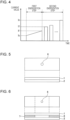
- control method in which the current is changed examples include “multistage energization (see Fig. 3 )" and “upslope energization (see Fig. 4 ).”
- a pressure welded portion around the nugget can be more firmly joined in the first energization step, and the occurrence of splashes in the subsequent second energization step can be reduced. Even when splashes occur, the amount of splashes can be reduced. In this manner, the deformation of the weld is small, and therefore the occurrence of cracking can be reduced.
- the energization in the first energization step may be multistage energization including first to m-th stages (m is an integer of 2 or more).
- the current values in the energization stages are denoted as I1' to Im' (kA).
- the current value I1' (kA) in the first stage is set to be equal to the current value Is at the start of the energization(kA), and the current value Im' (kA) in the m-th stage is set to be equal to the current value If (kA) at the end of the energization.
- the heat input to the pressure welded portion is insufficient.
- the pressure welded portion around the nugget cannot be firmly joined in the first energization step, and the effect of reducing the amount of splashes that may occur in the subsequent second energization step cannot be obtained.
- the energization time in the first energization step is controlled such that the sum of the energization times in the energization stages is within the energization time tp described above (100 to 500 ms).
- m is an integer of 2 or more. From the viewpoint of avoiding excessively complicated management of the welding conditions during the welding operation, m is preferably 5 or less.
- the energization in the first energization step may be upslope energization in which the current value is continuously increased from the current value Is at the start of the energization to the current value If at the end of the energization.
- the pressure welded portion around the nugget is firmly joined in the first energization step, and the amount of splashes in the subsequent second energization step can be reduced.
- the deformation of the weld is small, and therefore the occurrence of cracking can be reduced.
- the second energization step is performed.
- the current value during the repeated energization in the second energization step be increased gradually.
- the size of the nugget can be effectively increased.
- the second energization step it is effective to increase the size of the nugget in a stepwise manner in multiple stages in the repeated energization. If the current value in the repeated energization is constant, the effect of increasing the size of the nugget is large in the first half of the repeated energization, but the effect is relatively small in the second half. However, by increasing the current value gradually in the repeated energization, the effect of increasing the size of the nugget in a stepwise manner can be achieved significantly in both the first and second halves of the repeated energization.
- the second energization step is a multistage step including first to n-th stages (n is an integer of 2 or more) each including a cooling step of maintaining a non-energization state for 10 ms or longer and shorter than 160 ms and an energization step of performing energization for 20 ms or longer and shorter than 200 ms.
- the current value in the energization step in the first stage is denoted as I1 (kA)
- the current value in the energization step in the n-th stage (final stage) is denoted as In (kA).
- the current value in the first energization step in the above phrase “the current value I1 in the first stage is equal to or higher than the current value in the first energization step” is “the current value Ip" when a constant current is used (see Fig. 2 ) and is “the current value If at the end of the energization” when the current is changed (see Figs. 3 and 4 ).
- the non-energization time in the cooling step is shorter than 10 ms, the cooling effect is insufficient, and the weld is likely to deform largely, so that cracking tends to occur. If the non-energization time is 160 ms or longer, the effect of the multistage energization, i.e., the effect of increasing the size of the nugget by repeated energization, is not sufficient. Therefore, the non-energization time in the cooling step in each stage is set to be 10 ms or longer and shorter than 160 ms. The non-energization time is preferably 10 to 120 ms.
- the energization time in the energization step is shorter than 20 ms, the heat input is insufficient, so that the effect of increasing the size of the nugget cannot be achieved sufficiently. If the energization time is 200 ms or longer, an excessively large heat input is applied in one energization operation. In this case, the weld is likely to deform largely, and cracking tends to occur. Therefore, the energization time in the energization step in each stage is 20 ms or longer and shorter than 200 ms
- the size of the nugget is increased in the second energization step as described above.
- the non-energization time in the cooling step in each stage in the second energization step is set to preferably 10 to 80 ms, and the energization time in the energization step is set to preferably 20 to 100 ms.
- the non-energization time in the cooling step is more preferably 10 ms or longer and shorter than 80 ms, still more preferably 10 to 60 ms, and yet more preferably 10 to 20 ms.
- the current values in the energization steps in the energization stages in the second energization step satisfy the following condition in addition to formula (1).
- the current value during energization in the k-th stage is denoted as Ik (kA)
- I(k + 1) (kA) the current value during energization in the (k + 1)-th stage
- I(k + 1) the current value during energization in the (k + 1) (kA)
- I(k + 1) the current value during energization in the (k + 1) (kA)
- I(k + 1) ⁇ 1.3 ⁇ Ik.
- k is an integer of 1 or more and n - 1 or less.
- the number of steps (the number of stages) in the multistage energization in the second energization step is preferably 2 or more and 10 or less. If the number of stages is more than 10, the effect of increasing the size of the nugget is saturated. In this case, the effect obtained is unlikely to be large, and the total time of the overall welding process is long. Therefore, from the viewpoint of operational efficiency, the number of stages is preferably 10 or less.
- the diameter of the nugget formed at the completion of the first energization step is denoted as N1 (mm), and the diameter of the nugget formed at the completion of the first energization step and the second energization step is denoted as N2 (mm).
- N1 mm
- N2 mm
- the value of (N2 - N1) i.e., the amount of increase in the diameter of the nugget in the second energization step, is 0.1 ⁇ t (mm) or more.
- the value of (N2 - N1) is more preferably 0.3Vt (mm) or more and still more preferably 0.5Vt (mm) or more.
- the amount of increase in the diameter of the nugget in the second energization step is extremely large, the heat input is excessively large, and the deformation of the weld is large, so that cracking may occur. Therefore, the amount of increase is preferably 3.0 ⁇ t (mm) or less.
- the value of (N2 - N1) is more preferably 2.5Vt (mm) or less and still more preferably 2.0 ⁇ t (mm) or less.
- the present invention is applied to a resistance spot welding method for a sheet set in which the opposite sides of the sheet set to be in contact with the welding electrodes (upper and lower electrodes) disposed on the upper and lower sides of the sheet set or one of the opposite sides of the sheet set is a surface-treated steel sheet having a metal coated layer.
- the opposite sides of the sheet set to be in contact with the welding electrodes are two outermost steel sheets that are included in the sheet set including the plurality of steel sheets and are to be in contact with the upper and lower electrodes.
- the one of the opposite sides of the sheet set to be in contact with the welding electrodes is one of the two outermost steel sheets that are included in the sheet set including the plurality of steel sheets and are to be in contact with the upper and lower electrodes.
- the melting point of the metal coated layer used is lower than the melting point of the base material of the surface-treated steel sheet.
- the surface-treated steel sheet is a steel sheet having a metal coated layer on the surface of the base material (base steel sheet).
- the metal coated layer include: zinc coatings typified by electrogalvanized coatings and hot-dip galvanized coatings (including hot-dip galvannealed coatings); and zinc alloy coatings containing, in addition to zinc, another element such as aluminum or magnesium.
- the above-described surface-treated steel sheet is referred to as a "zinc-based coated steel sheet.” Therefore, in the present invention, at least one of the plurality of steel sheets included in the sheet set is a zinc-based coated steel sheet.
- the above-described zinc-based coated steel sheet is preferably a high strength steel sheet (high strength zinc-based coated steel sheet) having an equivalent carbon content (Ceq)(%) represented by formula (5) below of 0.20% or more and a tensile strength of 780 MPa or more.
- Ceq % C + Si/30 + Mn/20 + 2P + 4S
- each element symbol in formula (5) represents the content (% by mass) of the element, and the content is 0 when the element is not contained.
- the high strength steel sheet is highly sensitive to cracking, and the occurrence of cracking is likely to cause a problem. Therefore, the effects of the invention can be more effective when the equivalent carbon content is 0.20% or more.
- the upper limit of the equivalent carbon content is not particularly specified. Even when the energization pattern in the invention is applied to a steel sheet having an extremely high equivalent carbon content, i.e., extremely sensitive to cracking, the effect of preventing cracking may not be obtained sufficiently. Therefore, the equivalent carbon content (Ceq) is preferably 0.60% or less and more preferably 0.50% or less.
- the chemical composition of the high strength zinc-based coated steel sheet used in the present invention may be appropriately adjusted such that the equivalent carbon content (Ceq) is within the above-described range and the above-descried tensile strength is obtained.
- the thicknesses of the steel sheets to be resistance-spot-welded are preferably in the range of, for example, 0.5 mm or more and 3.0 mm or less.
- a steel sheet having a thickness within the above range can be preferably used for automobile members.
- the two or more steel sheets to be resistance-spot-welded may be steel sheets of the same type and having the same shape or may be steel sheets of different types and having different shapes.
- a combination of a surface-treated steel sheet having a metal coated layer and a steel sheet having no metal coated layer may be used.
- Fig. 1 shows a sheet set that includes two overlapping steel sheets and is being joined by the resistance spot welding method of the invention.
- a pair of welding electrodes i.e., a welding electrode 4 (a lower electrode) disposed on the lower side of the sheet set and a welding electrode 3 (an upper electrode) disposed on the upper side of the sheet set, are used to hold therebetween the overlapping steel sheets (a lower steel sheet 2 and an upper steel sheet 1), and the overlapping steel sheets are energized under the welding conditions described above under the application of pressure.
- the number of overlapping steel sheets is preferably 4 or less.
- the apparatus used to perform the resistance spot welding method of the invention and the welding electrodes used may be the following apparatus and electrodes.
- the tip type of the upper and lower electrodes No particular limitation is imposed on the tip type of the upper and lower electrodes.
- the tip type include a DR type (dome radius type), an R type (radius type), and a D type (dome type) specified in JIS C9304: 1999.
- the tip diameter of each electrode is, for example, 4 mm to 16 mm.
- the radius of curvature of the tip of each electrode is, for example, 10 mm to 400 mm.
- Flat electrodes having flat tip ends may also be used.
- the resistance spot welding of two overlapping steel sheets has been mainly described.
- the present invention can be similarly applicable to resistance spot welding of three or more overlapping steel sheets, and the same effects as above can be obtained.
- two steel sheets including at least one zinc-based coated steel sheet were used and disposed so as to overlap each other to form a sheet set (see Table 1).
- the upper and lower steel sheets used were each a hot-dip galvannealed (GA) steel sheet or a cold rolled steel sheet.
- the equivalent carbon content (Ceq) represented by formula (5) above, the tensile strength, and the thickness of each steel sheet are shown in Table 1.
- Each of the sheet sets was subjected to resistance spot welding under conditions shown in any of Tables 2-1 to 4-2 to produce a welded joint.
- Table 2-1 shows welding conditions in which the energization in the first energization step is performed using a constant current value and the energization in the second energization step includes multiple stages each including the cooling step and the energization step.
- Table 3-1 shows welding conditions in which the energization in the first energization step is performed using different current values (multistage energization) and the energization in the second energization step includes multiple stages each including the cooling step and the energization step.
- Table 4-1 shows welding conditions in which the energization in the first energization step is performed while the current value is changed (upslope energization) and the energization in the second energization step includes multiple stages each including the cooling step and the energization step.
- the "Second energization step" shown in Tables 2-1, 3-1, and 4-1 is a multistage step including first to n-th stages (n is an integer of 2 or more) each including the cooling step and the energization step.
- the “Current value I1' (kA) in the first stage” is “the current value Is (kA) at the start of the energization”
- the “Current value Im'(kA) in the final stage (m-th stage)” is “the current value If (kA) at the end of the energization.”
- the current value in the third stage i.e., the final stage, is the current value at the end of the energization.
- the resistance spot welding was performed at room temperature, and the welding electrodes (lower and upper electrodes) were water-cooled constantly.
- the lower and upper electrodes were each a chromium-copper-made DR-type electrode having a tip with a diameter (tip diameter) of 6 mm and a radius of curvature of 40 mm.
- the upper electrode was driven by a servo motor to control the welding pressure, and a DC power source was supplied during energization.
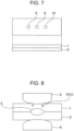
- FIGs. 5 to 7 the production of welded joints with the three different disturbance conditions described above will be described.
- Each figure shows a test specimen with steel sheets for resistance spot welding overlapping each other.
- the upper illustration shows a plan view, and the lower illustration shows a side view.
- the welded joint in the disturbance condition of "with no disturbance” was produced as follows. As shown in Fig. 5 , two steel sheets (an upper steel sheet 1 and a lower steel sheet 2) having a size of 30 mm ⁇ 100 mm (short side ⁇ long side) and produced from any of the above-described steel sheets were prepared. The steel sheets were disposed so as to overlap each other to obtain a test specimen, and the test specimen was welded under conditions shown in any of Tables 2-1, 3-1, and 4-1 to produce a welded joint having a weld 6 at the center. The weld 6 in the obtained welded joint was used to observe the nugget diameter and the presence or absence of cracking.
- the welded joint in the disturbance condition of "with a sheet gap” was produced as follows. As shown in Fig. 6 , two steel sheets (an upper steel sheet 1 and a lower steel sheet 2) having a size of 30 mm ⁇ 100 mm (short side ⁇ long side) and produced from any of the above-described steel sheets were prepared. Spacers 7 and 8 having a thickness of 1.6 mm and a size of 30 mm ⁇ 25 mm (long side ⁇ short side) were placed between the two steel sheets at opposite edge portions to obtain a test specimen. The test specimen was welded under conditions shown in any of Tables 2-1, 3-1, and 4-1 to produce a welded joint having a weld 6 at the center. The weld 6 in the obtained welded joint was used to observe the nugget diameter and the presence or absence of cracking.
- the test specimen in the disturbance condition of "with existing welds” was produced as follows. As shown in Fig. 7 , two steel sheets (an upper steel sheet 1 and a lower steel sheet 2) having a size of 30 mm ⁇ 100 mm (short side ⁇ long side) and produced from any of the above-described steel sheets were prepared. The steel sheets were disposed so as to overlap each other to form the test specimen. Welds 9 and 10 having a nugget diameter of 5 mm were disposed at positions spaced 20 mm from the center of the test specimen in the longitudinal direction. Then the test specimen was welded under conditions shown in any of Tables 2-1, 3-1, and 4-1 to produce a welded joint having a weld 6 at the center. The weld 6 in the obtained welded joint was used to observe the nugget diameter and the presence or absence of cracking.
- the nugget diameter, the amount of increase in the nugget diameter, and the presence or absence of cracking were evaluated and judged as follows.
- a welding test including only the first energization step was performed under one of the above disturbance conditions, and then a cross section was observed to measure the nugget diameter (N1) after the first energization step.
- the cross section obtained by cutting the weld was etched and observed under an optical microscope, and the diameter of the nugget between the steel sheets was measured.
- the measurement value obtained is shown in a "Nugget diameter N1 after first energization step" column in Tables 2-2, 3-2, or 4-2.
- a welding test was performed under one of the three disturbance conditions described above, and the welded joint obtained was used to measure the nugget diameter (N2) after the second energization step using the same method as above.
- the measurement value obtained is shown in a "Nugget diameter N2 after second energization step" column in Table 2-2, 3-2, or 4-2.
- a value calculated as (N2 - N1) and indicating the amount of increase in the nugget diameter in the second energization step is shown in an "N2 - N1" column in Table 2-2, 3-2, or 4-2.
Landscapes
- Engineering & Computer Science (AREA)
- Mechanical Engineering (AREA)
- Resistance Welding (AREA)
Applications Claiming Priority (2)
| Application Number | Priority Date | Filing Date | Title |
|---|---|---|---|
| JP2022112894 | 2022-07-14 | ||
| PCT/JP2023/019968 WO2024014146A1 (ja) | 2022-07-14 | 2023-05-29 | 抵抗スポット溶接方法 |
Publications (2)
| Publication Number | Publication Date |
|---|---|
| EP4494800A1 true EP4494800A1 (de) | 2025-01-22 |
| EP4494800A4 EP4494800A4 (de) | 2026-04-01 |
Family
ID=89536632
Family Applications (1)
| Application Number | Title | Priority Date | Filing Date |
|---|---|---|---|
| EP23839323.5A Pending EP4494800A4 (de) | 2022-07-14 | 2023-05-29 | Widerstandspunktschweissverfahren |
Country Status (6)
| Country | Link |
|---|---|
| EP (1) | EP4494800A4 (de) |
| JP (1) | JP7522977B2 (de) |
| KR (1) | KR20250002801A (de) |
| CN (1) | CN119365289A (de) |
| MX (1) | MX2024015448A (de) |
| WO (1) | WO2024014146A1 (de) |
Family Cites Families (11)
| Publication number | Priority date | Publication date | Assignee | Title |
|---|---|---|---|---|
| JP2003103377A (ja) | 2001-09-27 | 2003-04-08 | Nippon Steel Corp | 高強度めっき鋼板のスポット溶接方法 |
| JP3849539B2 (ja) | 2002-02-19 | 2006-11-22 | Jfeスチール株式会社 | 高張力亜鉛系めっき鋼板のスポット溶接方法 |
| JP4728926B2 (ja) * | 2006-10-16 | 2011-07-20 | 新日本製鐵株式会社 | 重ね抵抗スポット溶接方法 |
| JP5201116B2 (ja) | 2008-10-16 | 2013-06-05 | Jfeスチール株式会社 | 高強度鋼板の抵抗スポット溶接方法 |
| JP5359571B2 (ja) * | 2009-02-12 | 2013-12-04 | 新日鐵住金株式会社 | 高張力鋼板の抵抗溶接方法および抵抗溶接継手の製造方法 |
| JP5332857B2 (ja) * | 2009-04-20 | 2013-11-06 | 新日鐵住金株式会社 | 高張力鋼板の抵抗溶接方法 |
| JP5333560B2 (ja) * | 2011-10-18 | 2013-11-06 | Jfeスチール株式会社 | 高張力鋼板の抵抗スポット溶接方法及び抵抗スポット溶接継手 |
| JP6108017B2 (ja) * | 2015-09-03 | 2017-04-05 | 新日鐵住金株式会社 | スポット溶接方法 |
| JP6108018B2 (ja) | 2015-09-03 | 2017-04-05 | 新日鐵住金株式会社 | スポット溶接方法 |
| JP6584728B1 (ja) * | 2017-12-19 | 2019-10-02 | 日本製鉄株式会社 | 抵抗スポット溶接継手の製造方法 |
| KR102415946B1 (ko) * | 2018-06-29 | 2022-06-30 | 제이에프이 스틸 가부시키가이샤 | 저항 스폿 용접 방법 및 용접 부재의 제조 방법 |
-
2023
- 2023-05-29 EP EP23839323.5A patent/EP4494800A4/de active Pending
- 2023-05-29 JP JP2023547356A patent/JP7522977B2/ja active Active
- 2023-05-29 CN CN202380046661.5A patent/CN119365289A/zh active Pending
- 2023-05-29 KR KR1020247040768A patent/KR20250002801A/ko active Pending
- 2023-05-29 WO PCT/JP2023/019968 patent/WO2024014146A1/ja not_active Ceased
-
2024
- 2024-12-12 MX MX2024015448A patent/MX2024015448A/es unknown
Also Published As
| Publication number | Publication date |
|---|---|
| WO2024014146A1 (ja) | 2024-01-18 |
| KR20250002801A (ko) | 2025-01-07 |
| EP4494800A4 (de) | 2026-04-01 |
| MX2024015448A (es) | 2025-02-10 |
| JPWO2024014146A1 (de) | 2024-01-18 |
| JP7522977B2 (ja) | 2024-07-26 |
| CN119365289A (zh) | 2025-01-24 |
Similar Documents
| Publication | Publication Date | Title |
|---|---|---|
| KR101744427B1 (ko) | 조인트 강도가 우수한 고강도 강판의 스폿 용접 방법 | |
| EP3391988B1 (de) | Widerstandspunktschweissverfahren und verfahren zur herstellung eines geschweissten elements unter verwendung solches verfahrens | |
| EP2783782B1 (de) | Widerstandspunktschweissverbindung | |
| EP3266554B1 (de) | Widerstandspunktschweissvorrichtung | |
| EP4393628A1 (de) | Widerstandspunktgeschweisstes element und widerstandspunktschweissverfahren dafür | |
| EP3342524B1 (de) | Widerstandspunktschweissverfahren und verfahren zur herstellung eines geschweissten elements | |
| EP4563275A1 (de) | Geschweisstes element und herstellungsverfahren dafür | |
| US20240424595A1 (en) | Resistance spot welded joint and resistance spot welding method therefor | |
| KR102491219B1 (ko) | 저항 스폿 용접 부재 및 그 제조 방법 | |
| EP3266553A1 (de) | Widerstandspunktschweissverfahren und schweissverbindung | |
| EP4494800A1 (de) | Widerstandspunktschweissverfahren | |
| EP4563272A1 (de) | Geschweisstes element und verfahren zur herstellung davon | |
| EP4353394A1 (de) | Widerstandspunktschweissverfahren | |
| EP4585349A1 (de) | Widerstandspunktschweissverfahren | |
| EP4434667A1 (de) | Widerstandspunktgeschweisste verbindung und verfahren zur herstellung davon | |
| EP3995246B1 (de) | Verfahren zur herstellung einer widerstandpunktschweissverbindung | |
| EP4302916A1 (de) | Widerstandspunktschweissverfahren | |
| KR102589429B1 (ko) | 저항 스폿 용접 방법, 저항 스폿 용접 이음매의 제조 방법 | |
| EP4563273A1 (de) | Geschweisstes element und verfahren zur herstellung davon | |
| KR102871622B1 (ko) | 용접 이음매, 용접 부재 및 그 제조 방법, 그리고 저항 스폿 용접 방법 | |
| EP4563274A1 (de) | Geschweisstes element und herstellungsverfahren dafür | |
| EP4494798A1 (de) | Verfahren zur vorhersage der erzeugung von widerstandspunktschweissspritzern, widerstandspunktschweissverfahren und verfahren zur herstellung eines geschweissten elements | |
| WO2023153247A1 (ja) | 抵抗スポット溶接継手および抵抗スポット溶接方法 | |
| WO2025121277A1 (ja) | 抵抗スポット溶接部材およびその抵抗スポット溶接方法 |
Legal Events
| Date | Code | Title | Description |
|---|---|---|---|
| STAA | Information on the status of an ep patent application or granted ep patent |
Free format text: STATUS: THE INTERNATIONAL PUBLICATION HAS BEEN MADE |
|
| PUAI | Public reference made under article 153(3) epc to a published international application that has entered the european phase |
Free format text: ORIGINAL CODE: 0009012 |
|
| STAA | Information on the status of an ep patent application or granted ep patent |
Free format text: STATUS: REQUEST FOR EXAMINATION WAS MADE |
|
| 17P | Request for examination filed |
Effective date: 20241016 |
|
| AK | Designated contracting states |
Kind code of ref document: A1 Designated state(s): AL AT BE BG CH CY CZ DE DK EE ES FI FR GB GR HR HU IE IS IT LI LT LU LV MC ME MK MT NL NO PL PT RO RS SE SI SK SM TR |
|
| DAV | Request for validation of the european patent (deleted) | ||
| DAX | Request for extension of the european patent (deleted) | ||
| A4 | Supplementary search report drawn up and despatched |
Effective date: 20260302 |
|
| RIC1 | Information provided on ipc code assigned before grant |
Ipc: B23K 11/16 20060101AFI20260224BHEP Ipc: B23K 11/24 20060101ALI20260224BHEP Ipc: B23K 11/11 20060101ALI20260224BHEP |