EP4563272A1 - Geschweisstes element und verfahren zur herstellung davon - Google Patents
Geschweisstes element und verfahren zur herstellung davon Download PDFInfo
- Publication number
- EP4563272A1 EP4563272A1 EP23868130.8A EP23868130A EP4563272A1 EP 4563272 A1 EP4563272 A1 EP 4563272A1 EP 23868130 A EP23868130 A EP 23868130A EP 4563272 A1 EP4563272 A1 EP 4563272A1
- Authority
- EP
- European Patent Office
- Prior art keywords
- welding
- steel sheet
- weld
- layer
- steel sheets
- Prior art date
- Legal status (The legal status is an assumption and is not a legal conclusion. Google has not performed a legal analysis and makes no representation as to the accuracy of the status listed.)
- Pending
Links
Images


Classifications
-
- B—PERFORMING OPERATIONS; TRANSPORTING
- B23—MACHINE TOOLS; METAL-WORKING NOT OTHERWISE PROVIDED FOR
- B23K—SOLDERING OR UNSOLDERING; WELDING; CLADDING OR PLATING BY SOLDERING OR WELDING; CUTTING BY APPLYING HEAT LOCALLY, e.g. FLAME CUTTING; WORKING BY LASER BEAM
- B23K11/00—Resistance welding; Severing by resistance heating
- B23K11/10—Spot welding; Stitch welding
- B23K11/11—Spot welding
- B23K11/115—Spot welding by means of two electrodes placed opposite one another on both sides of the welded parts
-
- B—PERFORMING OPERATIONS; TRANSPORTING
- B23—MACHINE TOOLS; METAL-WORKING NOT OTHERWISE PROVIDED FOR
- B23K—SOLDERING OR UNSOLDERING; WELDING; CLADDING OR PLATING BY SOLDERING OR WELDING; CUTTING BY APPLYING HEAT LOCALLY, e.g. FLAME CUTTING; WORKING BY LASER BEAM
- B23K11/00—Resistance welding; Severing by resistance heating
- B23K11/16—Resistance welding; Severing by resistance heating taking account of the properties of the material to be welded
- B23K11/163—Welding of coated materials
- B23K11/166—Welding of coated materials of galvanized or tinned materials
-
- B—PERFORMING OPERATIONS; TRANSPORTING
- B23—MACHINE TOOLS; METAL-WORKING NOT OTHERWISE PROVIDED FOR
- B23K—SOLDERING OR UNSOLDERING; WELDING; CLADDING OR PLATING BY SOLDERING OR WELDING; CUTTING BY APPLYING HEAT LOCALLY, e.g. FLAME CUTTING; WORKING BY LASER BEAM
- B23K11/00—Resistance welding; Severing by resistance heating
- B23K11/24—Electric supply or control circuits therefor
- B23K11/241—Electric supplies
-
- B—PERFORMING OPERATIONS; TRANSPORTING
- B23—MACHINE TOOLS; METAL-WORKING NOT OTHERWISE PROVIDED FOR
- B23K—SOLDERING OR UNSOLDERING; WELDING; CLADDING OR PLATING BY SOLDERING OR WELDING; CUTTING BY APPLYING HEAT LOCALLY, e.g. FLAME CUTTING; WORKING BY LASER BEAM
- B23K2101/00—Articles made by soldering, welding or cutting
- B23K2101/006—Vehicles
-
- B—PERFORMING OPERATIONS; TRANSPORTING
- B23—MACHINE TOOLS; METAL-WORKING NOT OTHERWISE PROVIDED FOR
- B23K—SOLDERING OR UNSOLDERING; WELDING; CLADDING OR PLATING BY SOLDERING OR WELDING; CUTTING BY APPLYING HEAT LOCALLY, e.g. FLAME CUTTING; WORKING BY LASER BEAM
- B23K2101/00—Articles made by soldering, welding or cutting
- B23K2101/34—Coated articles ; Surface treated articles
-
- B—PERFORMING OPERATIONS; TRANSPORTING
- B23—MACHINE TOOLS; METAL-WORKING NOT OTHERWISE PROVIDED FOR
- B23K—SOLDERING OR UNSOLDERING; WELDING; CLADDING OR PLATING BY SOLDERING OR WELDING; CUTTING BY APPLYING HEAT LOCALLY, e.g. FLAME CUTTING; WORKING BY LASER BEAM
- B23K2103/00—Materials to be soldered, welded or cut
- B23K2103/02—Iron or ferrous alloys
- B23K2103/04—Steel or steel alloys
Definitions
- the present invention relates to a welded member produced by resistance-spot-welding steel sheets and more particularly to a welded member suitable for members of structural parts of automobiles etc. and a method for producing the welded member.
- a resistance spot welding method which is one type of lap resistance welding
- two or more overlapping steel sheets are held between a vertical pair of welding electrodes, and a high welding current is applied between the upper and lower electrodes for a short time while the steel sheets are pressed between the upper and lower welding electrodes to thereby join the steel sheets together.
- Fig. 1 shows an example in which two overlapping steel sheets 1 and 2 held between welding electrodes 4 and 5 are resistance-spot-welded. In this method, resistance heat generated by the application of a high welding current is used to obtain a spot-shaped weld 6.
- the spot-shaped weld 6 is called a nugget. Specifically, when the current is applied to the overlapping steel sheets, the steel sheets 1 and 2 are melted at their contact portion and then solidified to form the nugget. The steel sheets are thereby jointed together at the spot.
- TSS tensile shear strength
- the surface-treated steel sheet is a steel sheet having a metal coated layer on the surface of a base metal (base steel sheet).
- the metal coating include: zinc coatings typified by electrogalvanized coatings and hot-dip galvanized coatings (including hot-dip galvannealed coatings); and zinc alloy coatings containing, in addition to zinc, another element such as aluminum or magnesium.
- the melting points of the zinc coatings and the zinc alloy coatings are lower than the melting point of the base metal of the surface-treated steel sheet, and therefore the following problem occurs.
- LME cracking liquid metal embrittlement
- the low-melting point metal coated layer on the surface of the steel sheet melts during welding.
- the molten low-melting point metal penetrates into grain boundaries of the base metal of the surface-treated steel sheet and causes a reduction in grain boundary strength, and the cracking thereby occurs.
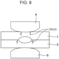
- the LME cracking occurs at various positions such as the surfaces of the steel sheets 1 and 2 that are in contact with the welding electrodes 4 and 5 and the surfaces of the steel sheets 1 and 2 at which the steel sheets are in contact with each other, as shown in Fig. 8 .
- Patent Literature 1 a steel sheet in a sheet set has a chemical composition in a specific range.
- the steel sheet proposed has a chemical composition including, in % by weight, C: 0.003 to 0.01%, Mn: 0.05 to 0.5%, P: 0.02% or less, sol. Al: 0.1% or less, Ti: 48 ⁇ (N / 14) to 48 ⁇ ⁇ (N / 14) + (S / 32) ⁇ %, Nb: 93 ⁇ (C / 12) to 0.1%, B: 0.0005 to 0.003%, N: 0.01% or less, and Ni: 0.05% or less, with the balance being Fe and incidental impurities.
- Patent Literature 2 proposes a spot welding method for high strength coated steel sheets.
- resistance spot welding is performed while the welding energization time and the holding time after welding energization are set such that the following conditional expressions (A) and (B) are satisfied.
- t is the thickness (mm) of the sheets
- WT is the welding energization time (ms)
- HT is the holding time (ms) after welding energization.
- Patent Literature 2 also proposes that the welding is performed using high tensile galvanized steel sheets with the amounts of alloying elements in the steel sheets set to be equal to or less than specific values while the energization time and the holding time of the electrodes after energization are set according to the thickness of the steel sheets.
- Patent Literature 3 proposes a method that uses an energization pattern including multi-stage energization having three or more stages. Specifically, welding conditions such as energization time and welding current are controlled such that an appropriate current range ( ⁇ I) is 1.0 kA or more and preferably 2.0 kA or more, and a cooling period is provided between the stages.
- the above appropriate current range is a current range in which a nugget having a diameter equal to or more than a desired nugget diameter and an unmelted thickness of 0.05 mm or more can be stably formed.
- Patent Literature 1 one problem with Patent Literature 1 is that the need to limit the amounts of the alloying elements in the steel sheets limits the application of the steel sheets that meet the required performance. In particular, since the degree of alloying in recent steel sheets having increased strength is increasing, the applications of the steel sheets in Patent Literature 1 are extremely limited.
- Patent Literature 2 proposes only the method for preventing cracking when the welding current is set to an excessively large value that causes splashes, and no reference is made to cracking in a state in which no splashes occur.
- Patent Literature 3 Problems with Patent Literature 3 are that many man-hours are required to obtain appropriate welding conditions and that the method cannot be applied to steel sheets and sheet sets in which the appropriate current range is not easily maintained. Moreover, in Patent Literature 2 and Patent Literature 3, the influence of the inclination angle of the electrodes is not studied, and therefore the measures against this influence are insufficient in some cases, in consideration of the actual operation performed during the assembly of automobiles.
- Patent Literature 1 By summarizing the common problem with Patent Literature 1 to Patent Literature 3 with consideration given to the joint strength, a technique for preventing the occurrence of LME cracking while the strength of the weld in the high strength steel sheet is maintained has not been proposed.
- the present invention has been made in view of the foregoing circumstances, and it is an object to provide a welded member having a resistance spot weld which can have high strength even in a high strength steel sheet and in which the occurrence of LME cracking is prevented and to provide a method for producing the welded member.
- LME cracking tends to occur in a resistance spot weld when excessively large tensile residual stress is generated in the resistance spot weld due to work disturbances etc. during welding.
- LME cracking is likely to occur in a region in which large local tensile stress is generated when the pair of welding electrodes are released after completion of energization and pressurization for resistance spot welding.
- the microstructure in the weld heat affected zone may be changed due to the influence of heat during welding, or alloying elements such as C may diffuse, so that the softened layer in the steel sheet surface layer in the weld heat affected zone may disappear. In this case, the intended effects of the invention cannot be obtained. Moreover, if the surface of the weld heat affected zone, particularly the steel sheet surface layer on the steel sheet faying surface side, is significantly soft, the strength of the resistance spot weld decreases.
- the inventors have arrived at the idea that, by controlling the hardness of the softened layer in the steel sheet surface layer in the weld heat affected zone within a given range, the strength of the resistance spot weld can be ensured and also the occurrence of LME cracking can be prevented.
- Figs. 3(A) to 3(C) are enlarged cross-sectional views each showing a weld heat affected zone (HAZ) of a welded member and the periphery thereof in a region corresponding to a region surrounded by a rectangular frame in Fig. 2 described later.
- the cross-sectional views in Fig. 3 are illustrations used to explain the softened layer, and the gap between the sheets shown in Fig. 2 is omitted.
- the steel sheet disposed on the lower side i.e., the lower sheet
- the steel sheet disposed on the lower side is the "steel sheet having the softened layer in the steel sheet surface layer" used in the invention.
- a welded member obtained by resistance-spot-welding a sheet set including a steel sheet having a softened layer in a steel sheet surface layer has the softened layer in the surface layer of the lower sheet that is located on the steel sheet faying surface 7 side.
- the softened layer is present in a weld heat affected zone (HAZ) and in a base metal zone.
- HAZ weld heat affected zone
- the softened layer in the weld heat affected zone basically decreases in thickness as one approaches a nugget 6a. However, as the influence of heat during welding increases, part of the softened layer in the weld heat affected zone may disappear completely due to diffusion of elements such as C as shown in Fig.
- softened layer in the steel sheet surface layer in the weld heat affected zone may not substantially disappear but remain as shown in Fig. 3(C) .
- softened layers present in weld heat affected zones that include those in the states shown in Figs. 3(A) to 3(C) are collectively referred to as the "softened layer in the steel sheet surface layer in the weld heat affected zone.”
- the present invention is based on the above findings and summarized as follows.
- a welded member and a method for producing the welded member can be provided in which a reduction in strength of the resistance spot weld caused by softening of the steel sheet surface layer can be prevented and no LME cracking occurs.
- Fig. 1 shows an example in which two steel sheets are resistance-spot-welded together.
- Fig. 2 shows a cross-sectional view in a thickness direction illustrating an example of the welded member of the invention and an enlarged cross-sectional view of a resistance spot weld in the welded member and the periphery thereof.
- the present invention is a welded member having a resistance spot weld (hereinafter referred to as a "weld") formed by resistance-spot-welding a sheet set including two or more overlapping steel sheets.
- a welding a resistance spot weld
- Fig. 2 shows an example of the welded member 10 including two overlapping steel sheets welded together.
- Both or one of the lower steel sheet 2 (lower sheet) and the upper steel sheet 1 (upper sheet) is the steel sheet having the softened layer described above.
- a weld 6 described later is formed at a steel sheet faying surface 7 at which the steel sheets 1 and 2 are in contact with each other.
- the weld 6 in the invention is formed only on the faying surface 7 side of the lower sheet 2.
- the weld 6 in the invention is formed on both the upper sheet 1 side and the lower sheet 2 side of the faying surface 7.
- all or at least one of the lowermost steel sheet (i.e., the lower sheet), the uppermost steel sheet (i.e., the upper sheet), and a steel sheet (i.e., a middle sheet) disposed therebetween is the steel sheet having the softened layer.
- the weld in the invention is formed so as to include the faying surfaces between the steel sheets.
- the weld in the invention is formed so as to include two faying surfaces at which the lower and middle sheets and the middle and upper sheets are in contact with each other.
- the three steel sheets used are each the steel sheet having the softened layer, the hardnesses of the softened layers in the steel sheet surface layers on the upper and lower sides of each faying surface are controlled.
- the weld in the invention will be described in detail.
- the weld formed in a steel set including two overlapping steel sheets is similar to the weld formed in a steel set including three or more overlapping steel sheets, and therefore Fig. 2 will be used for the following description.
- the total thickness of the sheet set is denoted as t all
- the minimum thickness of the weld is denoted as t weld . Then the total thickness (t all ) and the minimum thickness (t weld ) of the weld satisfy formula (1) shown below.
- the nanoindentation hardness at a position spaced 20 ⁇ m from the surface of the softened layer in the thickness direction is denoted as Hbs
- the nanoindentation hardness at a position spaced 1/4 the thickness from the surface of the softened layer in the thickness direction is denoted as Hbt.
- the ratio (t weld /t all ) of the minimum thickness to the total thickness does not satisfy formula (1) above, i.e., the ratio is less than or equal to the lower limit of formula (1), the reduction in the thickness of the weld 6 is significantly large. Therefore, the tensile residual stress generated in the weld 6 is excessively large, and LME cracking tends to occur. Moreover, this causes a reduction in the joint strength.
- the thickness of the sheet set is reduced by the pressurization by the pair of welding electrodes and the influence of heat during welding. Therefore, the upper limit of t weld /t all is less than 1.0.
- the lower limit of formula (1) is preferably 0.55 or more, and the upper limit of formula (1) is preferably 0.95 or less.
- the "minimum thickness (t weld ) of the weld” is the minimum thickness in the thickness direction in a region extending in the width direction within a nugget 6a, as shown in Fig. 2 .
- the minimum thickness (t weld ) can be measured by a method described later in Examples.
- the ratio (Hbs/Hbt) of the hardnesses in the base metal zone represented by formula (2) above is 0.8 or more, the tensile residual stress in the steel sheet surface layer is excessively large when the electrodes are released after the resistance spot welding, and, as a result, LME cracking tends to occur. If the ratio of the hardnesses in the base metal zone is 0.2 or less, a crack is easily formed in the steel sheet surface layer, and this causes a reduction in the joint strength.
- the lower limit of formula (2) is preferably 0.22 or more.
- the upper limit of formula (2) is preferably 0.75 or less.
- the strength of the weld can be ensured, and also the occurrence of LME cracking can be prevented.
- the following structure may be provided in addition to the structure described above.
- a position that is located on the steel sheet faying surface 7 and is spaced 400 ⁇ m from an edge 6c of the nugget of the weld in a direction toward the base metal is defined as a starting point (i.e., point A shown in Fig. 2 ).
- the nanoindentation hardness at a position spaced 20 ⁇ m from the starting point in the thickness direction is denoted as Hws, and the nanoindentation hardness at a position spaced 1/4 the thickness from the starting point in the thickness direction is denoted as Hwt.
- the ratio (Hws/Hwt) of the hardness in the weld heat affected zone 6b shown in formula (3) is less than 0.2, i.e., if the steel sheet surface layer in the weld heat affected zone 6b on the steel sheet faying surface 7 side on which stress concentration is large is significantly softened in comparison with the inside of the steel sheet in the weld heat affected zone 6b, the resistance to ductile cracking in the steel sheet surface layer in the weld heat affected zone decreases excessively. Therefore, the strength of the weld decreases.
- the steel sheet surface layer in the weld heat affected zone 6b is not softened relative to the inside of the steel sheet in the weld heat affected zone 6b. In this case, the effect of reducing the tensile residual stress in the weld is not obtained, and it is therefore difficult to prevent the occurrence of LME cracking. It is therefore effective that the relation 0.2 ⁇ Hws / Hwt ⁇ 1.0 is satisfied.
- the hardness ratio in the weld heat affected zone 6b satisfies the relation 0.25 ⁇ Hws / Hwt ⁇ 0.9. More preferably, the hardness ratio satisfies the relation 0.30 ⁇ Hws / Hwt ⁇ 0.8.
- the ratio (Hws/Hbs) of the hardnesses in the steel sheet surface layer shown in formula (4) is less than 0.8, the resistance to ductile cracking in the steel sheet surface layer in the weld heat affected zone decreases excessively, so that the strength of the weld decreases, as in the case of formula (1).
- the hardness ratio (Hws/Hwt) is 7.0 or more, the hardness of the steel sheet surface layer in the weld heat affected zone is excessively high. The higher the hardness, the larger the tensile residual stress after the electrodes are released. In this case, the effect of reducing the tensile residual stress in the weld cannot be obtained.
- the ratio of the hardnesses in the steel sheet surface layer satisfies the relation 1.0 ⁇ Hws / Hbs ⁇ 6.5, and it is more preferable that the ratio satisfies the relation 1.1 ⁇ Hws / Hbs ⁇ 6.0.
- the hardness of the steel sheet surface layer in the weld heat affected zone is higher than the hardness of the steel sheet surface layer in the base metal zone, excessive strain concentration in the weld heat affected zone when a tensile load is applied to the weld can be prevented, and this is advantageous to avoid the occurrence of fracture in the weld heat affected zone.
- the nanoindentation hardness (unit: GPa) can be measured by a nanoindentation hardness test as described later in Examples. No limitation is imposed on the nanoindentation hardness test in the invention. However, the hardness test may be performed using, for example, a nanoindentation apparatus (TI-950 TriboIndenter manufactured by Hysitron) according to ISO 14577.
- a nanoindentation apparatus TI-950 TriboIndenter manufactured by Hysitron
- the strength of the weld is influenced by the thicknesses of the overlapping steel sheets and their tensile strengths. Therefore, in the present invention, it is preferable that the ratio (Hws/Hwt) of the hardness of the steel sheet surface layer to the hardness of the inside of the steel sheet within the weld heat affected zone is appropriately controlled according to the thicknesses of the steel sheets and their tensile strengths. In this manner, the effects of the invention can be obtained more effectively.
- the thickness of a steel sheet is denoted as t (mm), and the tensile strength of the steel sheet is denoted as TS (MPa).
- t the thickness of a steel sheet
- TS the tensile strength of the steel sheet
- the steel sheet having the softened layer satisfies the following formula (5). - ⁇ (1000 ⁇ t / TS) - 0.25 ⁇ / 35 + 0.2 ⁇ (Hws / Hwt) ⁇ 1.0 (5)
- Hws is the nanoindentation hardness at the position spaced 20 ⁇ m from the starting point in the thickness direction
- Hwt is the nanoindentation hardness at the position space 1/4 the thickness from the starting point in the thickness direction.
- the thickness (t) of the steel sheet having the softened layer is large, the cross-sectional area of the weld heat affected zone is large. In this case, when a tensile load is applied to the weld, fracture tends to occur in the nugget rather than in the weld heat affected zone. Therefore, even when the surface layer in the weld heat affected zone is softened significantly, the strength of the weld is unlikely to decrease. Thus, the larger the thickness (t) of the steel sheet, the smaller the preferred lower limit of Hws/Hwt.
- the tensile strength (TS) of the steel sheet having the softened layer When the tensile strength (TS) of the steel sheet having the softened layer is large, martensitic transformation occurs due to the influence of heat during welding, so that the weld heat affected zone generally tends to be hardened. In this case, the difference in hardness between the softened layer in the steel sheet surface layer and the inside of the steel sheet is large, and this causes the surface layer in the weld heat affected zone to be softened, and therefore the strength of the weld tends to be lowered. Specifically, the higher the tensile strength (TS) of the steel sheet, the larger the preferred lower limit of Hws/Hwt.
- the lower limit of formula (5) is preferably more than or equal to - ⁇ (1000 ⁇ t / TS) - 0.25 ⁇ / 35 + 0.3.
- the upper limit of formula (5) is preferably 0.9 or less.
- formula (6) is further satisfied.
- the lower limit of formula (6) is preferably 0.5 or more, and the upper limit of formula (6) is preferably 2.5 or less.
- the tensile strength of the steel sheet having the softened layer is preferably TS ⁇ 980 MPa. This is because, when the high strength steel sheet satisfies this relation, the effects of the invention can be obtained more effectively.
- At least one of the two or more overlapping steel sheets is a steel sheet having a softened layer in a steel sheet surface layer as described above.
- the steel sheet having the softened layer in the steel sheet surface layer will be described.
- Fig. 4 shows an example of the steel sheet having the softened layer in the steel sheet surface layer.
- the steel sheet having the softened layer include a galvanized steel sheet having a galvanized layer on the softened layer and a steel sheet having a Si internally oxidized layer as the outermost surface layer in the softened layer.
- Fig. 4 shows, as an example, a steel sheet having a structure including a softened layer, a Si internally oxidized layer, a galvanized layer, and an Fe-based precoated layer described later.
- the galvanized steel sheet may include the Fe-based precoated layer between the softened layer and the galvanized layer.
- the Fe-based precoated layer which is a soft layer
- the steel sheet surface layer can be further softened.
- the precoated layer is an Fe-based electroplated layer.
- the Fe-based electroplated layer that can be used include, in addition to pure iron, alloy coated layers such as an Fe-B alloy, an Fe-C alloy, an Fe-P alloy, an Fe-N alloy, an Fe-O alloy, an Fe-Ni alloy, an Fe-Mn alloy, an Fe-Mo alloy, and an Fe-W alloy. No particular limitation is imposed on the chemical composition of the Fe-based electroplated layer.
- the chemical composition contains one or two or more elements selected from the group consisting of B, C, P, N, O, Ni, Mn, Mo, Zn, W, Pb, Sn, Cr, V, and Co in a total amount of 10% by mass or less with the balance being Fe and incidental impurities.
- the total amount of elements other than Fe is prevented, and the Fe-based electroplated layer can be formed at low cost.
- the coating weight per side of the Fe-based electroplated layer is preferably 0.5 g/m 2 or more.
- the coating weight is more preferably 1.0 g/m 2 or more.
- No particular limitation is imposed on the upper limit of the coating weight per side of the Fe-based electroplated layer.
- the coating weight per side of the Fe-based electroplated layer is preferably 60 g/m 2 or less.
- the coating weight is preferably 50 g/m 2 or less, more preferably 40 g/m 2 or less, and still more preferably 30 g/m 2 or less.
- the thickness of the Fe-based electroplated layer is measured as follows. After the hot-dip galvanization, a 10 ⁇ 15 mm sample is cut from the high-strength hot-dip galvannealed steel sheet and embedded in a resin to prepare a cross-section-embedded sample. The cross section of the sample is observed at three randomly selected points using a scanning electron microscope (SEM) at an acceleration voltage of 15 kV at a magnification of 2000X to 10000X depending on the thickness of the Fe-based electroplated layer. The average value of the thicknesses in the three viewing fields is determined and multiplied by the specific gravity of iron to convert the thickness to the coating weight per side of the Fe-based electroplated layer.
- SEM scanning electron microscope
- the surface of an unannealed high strength cold rolled steel sheet is subjected to Fe-based electroplating treatment to obtain an unannealed Fe-based electroplated steel sheet.
- Fe-based electroplating treatment method may be a sulfuric acid bath, a hydrochloric acid bath, or a mixture thereof.
- the unannealed high strength cold rolled steel sheet subjected to cold rolling may be subjected to the Fe-based electroplating treatment without oxidation treatment in, for example, a preheating furnace.
- the content of Fe ions in the Fe-based electroplating bath before the start of energization is preferably 1.0 mol/L or more in terms of Fe 2+ .
- the coating weight of Fe is sufficient.
- the effects of the invention can be obtained more effectively.
- the effects of the invention are still more effective.
- the steel sheet shown in Fig. 4 includes the Si internally oxidized layer within the softened layer.
- the Si internally oxidized layer can be formed as the outermost surface layer of the steel sheet by increasing the dew point during annealing when the steel sheet is produced, and the behavior of the other alloying elements during the formation of the Si internally oxidized layer is also controlled. In this manner, the softened layer can be formed.
- the effects of the invention can be obtained more effectively.
- the "Si internally oxidized layer” is a region in which the Si oxide is formed in crystal grains and/or part of crystal grain boundaries.
- FIGs. 5 and 6 are top views showing the vicinities of the welds of the welded members (illustrations of the welded members as viewed from above).
- the average of the shortest distances (H 1 ) from the centers of welding points of welds to an end face of the steel sheets is 3 mm or more.
- the average (H 2 ) of the center-to-center distances between adjacent welding points is preferably 6 mm or more.
- the "average (H 1 ) of the shortest distances from the centers of the welding points of the welds to the end face of the steel sheets” is determined by specifying an end face of the steel sheets closest to the centers of the welding points and measuring the distances from the welding points to the end face, as shown in Fig. 5 .
- the average for five appropriately selected welding points is used as the "average shortest distance.”
- the average for all the welding points is used as the "average shortest distance.”
- the average shortest distance (H 1 ) is less than 3 mm, the sheets around the nuggets are insufficiently pressed on the steel sheet end face side, so that the molten metal easily splashes from the gap between the sheets toward the steel sheet end face. Therefore, splashes occur significantly during welding, and variations in nugget diameters are likely to increase, so that the strength of the welds becomes unstable.
- the average shortest distance (H 1 ) is preferably 1000 mm or less.
- the "average (H 2 ) of the center-to-center distances between adjacent welding points" is determined by measuring the center-to-center distances between adjacent welding points. If the average (H 2 ) of the center-to-center distances between welding points is less than 6 mm, a diverted flow to an existing welding point occurs during welding, and the current density in the weld decreases. In this case, the nugget diameter tends to be small, and the strength of the weld tends to decrease. Moreover, the weld is restrained by the existing welding point, and the tensile residual stress increases, so that LME cracking tends to occur. No limitation is imposed on the upper limit of the average of the center-to-center distances between welding points. From the viewpoint of ensuring the strength and stiffness of the welded member, the average (H 2 ) of the center-to-center distances between welding points is preferably 100 mm or less.
- the welded member of the invention is produced through a production process including a preparation step of disposing two or more steel sheets so as to overlap each other to prepare a sheet set and a welding step of resistance-spot-welding the sheet set.
- two or more steel sheets including at least one steel sheet having the softened layer described above are prepared. Then the two or more steel sheets are disposed so as to overlap each other to prepare a sheet set. For example, as shown in Fig. 1 , the two overlapping steel sheets 1 and 2 are used to prepare a sheet set. The description of the steel sheets has already been provided and will be omitted. Next, the welding step is performed.
- the welding step includes an energization step and an electrode holding step described later.
- the sheet set prepared in the preparation step is joined together.
- the sheet set is held between a pair of welding electrodes 4 and 5 disposed on the upper and lower sides of the sheet set and then energized under the application of pressure while the welding conditions are controlled to prescribed conditions.
- the weld 6 in the invention described above is formed between the steel sheets 1 and 2 at the faying surface 7 between the steel sheets, and the steel sheets can thereby be joined together (see Fig. 2 ).
- a steel sheet having a softened layer and a steel sheet having no softened layer are used to prepare a sheet set, they are stacked such that the side with the softened layer is present at the faying surface between the steel sheets.
- the steel sheet having the softened layer is a galvanized steel sheet (a GI steel sheet, a GA steel sheet, or an EG steel sheet) having a galvanized layer
- the steel sheets are stacked such that the side with the softened layer is present at the faying surface between the steel sheets.
- the softened layer and/or the galvanized layer is present also at the steel sheet surface in contact with an electrode.
- a welder usable for the resistance spot welding method in the present invention may be a welder that includes a pair of upper and lower electrodes and can perform welding while the welding pressure and the welding current are controlled freely.
- the present invention is applicable to both DC and AC welding power sources.
- the "current" means the "effective current.”
- No particular limitation is imposed on the pressurizing mechanism (such as an air cylinder or a servo motor) of the welder, its type (e.g., a stationary or robot gun type), and the shape of the electrodes.
- Examples of the type of welding electrode tip include a DR type (dome radius type), an R type (radius type), and a D type (dome type) specified in JIS C 9304: 1999.
- the tip diameter of the welding electrodes is, for example, 4 mm to 16 mm.
- the welding step includes the energization step and the electrode holding step.
- the sheet set is held between the pair of welding electrodes to perform energization for joining under the application of pressure.
- one or two or more of states (a) to (e) described below are satisfied at at least one welding point immediately before the application of pressure by the welding electrodes.
- the energization step the energization is performed under the welding conditions of a welding pressure of 2.0 to 10.0 kN and a welding current of 4.0 to 15.0 kA for an energization time of 0.1 to 2.0 s.
- the electrode holding step the welding pressure holding time after completion of the energization is denoted as Th (s), and Th satisfies the relation of formula (7).
- the welding pressure is preferably 3.0 kN or more and is preferably 7.0 kN or less.
- the welding current is preferably 5.0 kA or more and is preferably 12.0 kA or less.
- the energization time is shorter than 0.1 s, the diffusion of alloying elements in the weld heat affected zone may be insufficient, and the hardness of the softened layer in the weld heat affected zone may be almost unchanged relative to the hardness of the base metal.
- topological strain concentration is larger than that in the base metal. Therefore, when the hardness of the softened layer in the weld heat affected zone is almost unchanged relative to the hardness of the base metal, strain concentration caused by the softening of the steel sheet surface layer in the weld heat affected zone is superimposed on the topological strain concentration, and this results in a reduction in TSS.
- the energization time is preferably 0.10 s or longer.
- the energization time is preferably 0.12 s or longer and is preferably 1.5 s or shorter.
- the energization time is more preferably longer than or equal to (0.13 ⁇ ⁇ (t all ⁇ H bs / H bt )) s and still more preferably longer than or equal to (0.19 ⁇ ⁇ (t all ⁇ H bs / H bt )) s. This is because of the following reasons. As the total sheet thickness increases, the energization time required to obtain a sufficient nugget diameter increases. As the value of H bs /H bt , which is the ratio of the hardnesses in the base metal zone, increases, LME cracking is more likely to occur, so that the energization time necessary to facilitate alloying and discharge of Zn coating from a corona bond portion increases. The energization time is still more preferably 0.30 s or longer.
- the resistance spot welding may be performed using multiple welding pressures, multiple current values, or in a specific pattern using a combination of energization and non-energization.
- the minimum welding pressure during the energization is set to 2.0 kN or more, and the maximum welding pressure is set to 10.0 kN or less.
- the minimum current value during the energization except for a non-energization period is set to 4.0 kA or more, and the maximum current value is set to 15.0 kA or less.
- the total energization time except for the non-energization period is set to 0.1 s or longer and 2.0 s or shorter.
- the electrode holding step is the step of holding the welding electrodes at a certain welding pressure after completion of the energization to prevent the occurrence of blowholes.
- the welding pressure holding time after completion of the energization is denoted as Th (s).
- Th (s) the welding pressure holding time satisfies the relation of formula (7) below.
- the effects of the invention can be obtained effectively.
- Hbs is the nanoindentation hardness at the position spaced 20 ⁇ m from the surface of the softened layer in the base metal zone in the thickness direction
- Hbt is the nanoindentation hardness at the position spaced 1/4 the thickness from the surface of the softened layer in the thickness direction.
- the welding pressure holding time (Th) is excessively short, the temperature after the electrodes are released increases, and LME cracking tends to occur. If the welding pressure holding time (Th) is excessively long, the takt time per welding point is long, and the productivity decreases. Moreover, since the cooling rate of the weld increases, the microstructure of the weld is embrittled. In this case, the joint strength decreases, and the weld tends to undergo delayed fracture.
- the larger the hardness ratio (Hbs/Hbt) in the base metal zone i.e., the smaller the degree of softening of the steel sheet surface layer relative to that inside the steel sheet in the base metal zone
- the lower limit of the welding pressure holding time (Th) be set to a large value.
- the larger the Hbs/Hbt the more likely the microstructure of the steel sheet surface layer in the weld is to be embrittled. It is therefore necessary that the upper limit of the Th be set to a small value.
- the welding pressure holding time is the time satisfying formula (7).
- the lower limit of formula (7) is preferably longer than or equal to ⁇ (Hbs / Hbt) - 0.2 ⁇ / 30 + 0.02.
- the upper limit of formula (7) is preferably shorter than or equal to [- ⁇ (Hbs / Hbt) - 0.2 ⁇ / 3] + 1.0.
- formula (8) is further satisfied.
- the lower limit of formula (8) is more preferably 0.02 or longer and still more preferably 0.17 or longer.
- the upper limit of formula (8) is more preferably 1.0 or shorter.
- Sheet sets shown in Table 1 were used to produce welded joints (welded members) under welding conditions shown in Table 2.
- a steel sheet 1, a steel sheet 2, and a steel sheet 3 shown in Table 1 were sequentially disposed from the upper side so as to overlap each other.
- "None” in the coating columns in Table 1 means a steel sheet (cold-rolled steel sheet) having no coated layer.
- “Yes” in “Softened layer in steel sheet surface layer” means the state in which a softened layer is present in a steel sheet surface layer
- “Yes” in “Internally oxidized layer” means the state in which a Si internally oxidized layer is present in a steel sheet surface layer, as shown in Fig. 4 .
- “Yes” in "Fe-based precoating” means the state in which a Fe-based precoating is present on a steel sheet surface layer, as shown in Fig. 4 .
- Each symbol shown in the "State immediately before pressurization" column corresponds to one of (a) to (e) shown in the welding work disturbances described above.
- the welder used was a servo motor pressing-type single-phase AC (50 Hz) resistance welder attached to a welding gun.
- the pair of electrode tips used were chromium-copper DR-type electrodes having a tip curvature radius R of 40 mm and a tip diameter of 6 mm.
- TSS of each welded joint and the presence or absence of LME cracking were evaluated by methods described below. Methods described below were used to measure the thicknesses (t all and t weld ) in each welded joint and the nanoindentation hardnesses (Hbs, Hbt, Hws, and Hwt) at different positions.
- the total thickness (t all ) of the sheet set was determined by measuring the thicknesses of the steel sheets before welding and summing the thicknesses to compute the total thickness.
- the minimum thickness (t weld ) of the weld was determined by measuring the lengths in the thickness direction in a region extending in the width direction within the nugget at 100 ⁇ m intervals and determining the minimum value used as the "minimum thickness" (see Fig. 2 ). The obtained values were used to determine the value of "t weld /t all .”
- One of the produced welded joints was cut using a micro-cutter along a plane passing through the center of the weld, and a nanoindentation hardness test was performed in the weld heat affected zone and in the base metal zone.
- a nanoindentation hardness test a triangular pyramidshaped diamond indenter was pressed into a measurement position with a pressing load of 500 ⁇ N to obtain a loaddisplacement curve from the start of the application of the load to the completion of unloading, and then the hardness was determined using the Oliver-Pharr analysis method.
- the nanoindentation hardnesses in the base metal zone were measured as follows. Specifically, as shown in Fig. 2 , in the base metal zone in the steel sheet having the softened layer (the lower sheet 2 shown in Fig. 2 ), the nanoindentation hardness (Hbs) at the position spaced 20 ⁇ m from the surface of the softened layer in the thickness direction was measured, and the nanoindentation hardness (Hbt) at the position spaced 1/4 the thickness from the surface of the softened layer in the thickness direction was measured.
- the measurement positions in the base metal zone were positions spaced 500 0 ⁇ m from the intersection of the outer edge of the weld heat affected zone and the faying surface 7 between the steel sheets in the direction toward the base metal.
- the nanoindentation hardnesses in the weld heat affected zone were measured as follows. Specifically, as shown in Fig. 2 , in the steel sheet having the softened layer (the lower sheet 2 shown in Fig. 2 ), the position located on the steel sheet faying surface and spaced 400 ⁇ m from the edge of the nugget in the direction toward the base metal is defined as the starting point A. The nanoindentation hardness (Hws) at the position spaced 20 ⁇ m from the starting point A in the thickness direction was measured, and the nanoindentation hardness (Hwt) at the position spaced 1/4 the thickness from the starting point A in the thickness direction was measured.
- the tensile shear strength (TSS) was evaluated based on a tensile shear test method (JIS Z 3136).
- JIS Z 3136 tensile shear test method
- shear tensile test pieces were cut from the steel sheets shown in Table 1, and sheet sets shown in Table 1 were resistance-spot-welded under welding conditions shown in Table 3 to produce welded joints (test specimens) used for the test.
- test specimen for the TSS evaluation had a shape specified in JIS Z 3136.
- sheet sets including three overlapping sheets such as sheet set No. H in Table 1
- the evaluation was performed such that a tensile load was applied to the steel sheet 2 and the steel sheet 3 as shown in Fig. 7 .
- the TSS was evaluated according to the following criteria.
- test specimen was rated pass (had good shear tensile strength).
Landscapes
- Engineering & Computer Science (AREA)
- Mechanical Engineering (AREA)
- Resistance Welding (AREA)
Applications Claiming Priority (2)
| Application Number | Priority Date | Filing Date | Title |
|---|---|---|---|
| JP2022150135 | 2022-09-21 | ||
| PCT/JP2023/033590 WO2024063009A1 (ja) | 2022-09-21 | 2023-09-14 | 溶接部材およびその製造方法 |
Publications (2)
| Publication Number | Publication Date |
|---|---|
| EP4563272A1 true EP4563272A1 (de) | 2025-06-04 |
| EP4563272A4 EP4563272A4 (de) | 2025-12-24 |
Family
ID=90454401
Family Applications (1)
| Application Number | Title | Priority Date | Filing Date |
|---|---|---|---|
| EP23868130.8A Pending EP4563272A4 (de) | 2022-09-21 | 2023-09-14 | Geschweisstes element und verfahren zur herstellung davon |
Country Status (7)
| Country | Link |
|---|---|
| US (1) | US20260108974A1 (de) |
| EP (1) | EP4563272A4 (de) |
| JP (1) | JP7485242B1 (de) |
| KR (1) | KR20250048091A (de) |
| CN (1) | CN119855671A (de) |
| MX (1) | MX2025002892A (de) |
| WO (1) | WO2024063009A1 (de) |
Families Citing this family (1)
| Publication number | Priority date | Publication date | Assignee | Title |
|---|---|---|---|---|
| JP7824559B1 (ja) * | 2025-05-30 | 2026-03-05 | 日本製鉄株式会社 | 接合部品 |
Family Cites Families (12)
| Publication number | Priority date | Publication date | Assignee | Title |
|---|---|---|---|---|
| JPS6282194U (de) * | 1985-11-08 | 1987-05-26 | ||
| JPH0299292A (ja) * | 1988-10-04 | 1990-04-11 | Shinko Kogyo Co Ltd | レーザ加工用ノズル |
| JPH09192870A (ja) * | 1996-01-10 | 1997-07-29 | Sumitomo Heavy Ind Ltd | レーザ加工ヘッド、レーザ加工装置及びレーザ加工方法 |
| JPH10195597A (ja) | 1996-11-14 | 1998-07-28 | Sumitomo Metal Ind Ltd | 接合性に優れた薄鋼板 |
| JPH10225788A (ja) * | 1997-02-14 | 1998-08-25 | Koike Sanso Kogyo Co Ltd | レーザ切断方法及びレーザ切断トーチ |
| JP2003103377A (ja) | 2001-09-27 | 2003-04-08 | Nippon Steel Corp | 高強度めっき鋼板のスポット溶接方法 |
| JP3849539B2 (ja) | 2002-02-19 | 2006-11-22 | Jfeスチール株式会社 | 高張力亜鉛系めっき鋼板のスポット溶接方法 |
| JP5206479B2 (ja) | 2009-02-20 | 2013-06-12 | 三菱マテリアル株式会社 | 多結晶シリコン製造装置 |
| JP2015077604A (ja) * | 2013-10-15 | 2015-04-23 | 三菱重工業株式会社 | 溶接装置 |
| PL3287539T3 (pl) * | 2015-04-22 | 2020-06-01 | Nippon Steel Corporation | Blacha stalowa cienka powlekana galwanicznie |
| JP2020082102A (ja) * | 2018-11-19 | 2020-06-04 | 株式会社神戸製鋼所 | 接合構造体及び接合構造体の製造方法 |
| JP6901050B1 (ja) | 2019-07-30 | 2021-07-14 | Jfeスチール株式会社 | 高強度鋼板およびその製造方法 |
-
2023
- 2023-09-14 WO PCT/JP2023/033590 patent/WO2024063009A1/ja not_active Ceased
- 2023-09-14 KR KR1020257007654A patent/KR20250048091A/ko active Pending
- 2023-09-14 CN CN202380065294.3A patent/CN119855671A/zh active Pending
- 2023-09-14 US US19/110,320 patent/US20260108974A1/en active Pending
- 2023-09-14 EP EP23868130.8A patent/EP4563272A4/de active Pending
- 2023-09-14 JP JP2023572734A patent/JP7485242B1/ja active Active
-
2025
- 2025-03-11 MX MX2025002892A patent/MX2025002892A/es unknown
Also Published As
| Publication number | Publication date |
|---|---|
| CN119855671A (zh) | 2025-04-18 |
| JPWO2024063009A1 (de) | 2024-03-28 |
| MX2025002892A (es) | 2025-04-02 |
| KR20250048091A (ko) | 2025-04-07 |
| EP4563272A4 (de) | 2025-12-24 |
| US20260108974A1 (en) | 2026-04-23 |
| JP7485242B1 (ja) | 2024-05-16 |
| WO2024063009A1 (ja) | 2024-03-28 |
Similar Documents
| Publication | Publication Date | Title |
|---|---|---|
| EP4563275A1 (de) | Geschweisstes element und herstellungsverfahren dafür | |
| EP4393628A1 (de) | Widerstandspunktgeschweisstes element und widerstandspunktschweissverfahren dafür | |
| CN112584959B (zh) | 电阻点焊构件及其制造方法 | |
| EP3862125A1 (de) | Verbundene struktur und verfahren zur herstellung einer verbundenen struktur | |
| EP4371688A1 (de) | Widerstandspunktgeschweisste verbindung und widerstandspunktschweissverfahren dafür | |
| EP4371687A1 (de) | Widerstandspunktschweissverbindung und widerstandspunktschweissverfahren dafür | |
| EP4592416A1 (de) | Widerstandspunktgeschweisste verbindung und widerstandspunktschweissverfahren dafür | |
| EP4534227A1 (de) | Punktschweissverbindung und verfahren zur herstellung einer punktschweissverbindung | |
| US20260108974A1 (en) | Welded member and method for producing the same | |
| EP4640359A1 (de) | Punktschweissverbindung, verfahren zur herstellung einer punktschweissverbindung und automobilkomponente | |
| EP4563273A1 (de) | Geschweisstes element und verfahren zur herstellung davon | |
| EP4484044B1 (de) | Schweissverbindung, schweisselement, verfahren zur herstellung davon und widerstandspunktschweissverfahren | |
| EP4434667A1 (de) | Widerstandspunktgeschweisste verbindung und verfahren zur herstellung davon | |
| EP4563274A1 (de) | Geschweisstes element und herstellungsverfahren dafür | |
| EP4353393A1 (de) | Widerstandspunktschweissverbindung und widerstandspunktschweissverfahren dafür | |
| US20260091444A1 (en) | Welded member and method for producing the same | |
| EP3995246B1 (de) | Verfahren zur herstellung einer widerstandpunktschweissverbindung | |
| EP4663332A1 (de) | Widerstandspunktschweissverfahren und verfahren zur herstellung eines geschweissten elements | |
| EP4484045B1 (de) | Schweissverbindung, schweissbauteil, verfahren zu dessen herstellung und widerstandspunktschweissverfahren | |
| EP4420817A1 (de) | Widerstandspunktgeschweisste verbindung und widerstandspunktschweissverfahren | |
| JP7636671B2 (ja) | スポット溶接継手、自動車用部品、及びスポット溶接継手の製造方法 | |
| EP4494800A1 (de) | Widerstandspunktschweissverfahren | |
| EP4353394A1 (de) | Widerstandspunktschweissverfahren | |
| WO2026028851A1 (ja) | 抵抗スポット溶接継手の製造方法及びめっき層の融点予測方法 |
Legal Events
| Date | Code | Title | Description |
|---|---|---|---|
| STAA | Information on the status of an ep patent application or granted ep patent |
Free format text: STATUS: THE INTERNATIONAL PUBLICATION HAS BEEN MADE |
|
| PUAI | Public reference made under article 153(3) epc to a published international application that has entered the european phase |
Free format text: ORIGINAL CODE: 0009012 |
|
| STAA | Information on the status of an ep patent application or granted ep patent |
Free format text: STATUS: REQUEST FOR EXAMINATION WAS MADE |
|
| 17P | Request for examination filed |
Effective date: 20250225 |
|
| AK | Designated contracting states |
Kind code of ref document: A1 Designated state(s): AL AT BE BG CH CY CZ DE DK EE ES FI FR GB GR HR HU IE IS IT LI LT LU LV MC ME MK MT NL NO PL PT RO RS SE SI SK SM TR |
|
| A4 | Supplementary search report drawn up and despatched |
Effective date: 20251121 |
|
| RIC1 | Information provided on ipc code assigned before grant |
Ipc: B23K 11/11 20060101AFI20251117BHEP Ipc: B23K 11/16 20060101ALI20251117BHEP |
|
| DAV | Request for validation of the european patent (deleted) | ||
| DAX | Request for extension of the european patent (deleted) |