EP4494802A1 - Système de manipulation de tube pour machine de travail de tube et machine de travail de tube laser comprenant ledit système de manipulation de tube - Google Patents
Système de manipulation de tube pour machine de travail de tube et machine de travail de tube laser comprenant ledit système de manipulation de tube Download PDFInfo
- Publication number
- EP4494802A1 EP4494802A1 EP23186119.6A EP23186119A EP4494802A1 EP 4494802 A1 EP4494802 A1 EP 4494802A1 EP 23186119 A EP23186119 A EP 23186119A EP 4494802 A1 EP4494802 A1 EP 4494802A1
- Authority
- EP
- European Patent Office
- Prior art keywords
- tube
- manipulator
- handling system
- longitudinal direction
- gripping means
- Prior art date
- Legal status (The legal status is an assumption and is not a legal conclusion. Google has not performed a legal analysis and makes no representation as to the accuracy of the status listed.)
- Withdrawn
Links
Images


Classifications
-
- B—PERFORMING OPERATIONS; TRANSPORTING
- B23—MACHINE TOOLS; METAL-WORKING NOT OTHERWISE PROVIDED FOR
- B23K—SOLDERING OR UNSOLDERING; WELDING; CLADDING OR PLATING BY SOLDERING OR WELDING; CUTTING BY APPLYING HEAT LOCALLY, e.g. FLAME CUTTING; WORKING BY LASER BEAM
- B23K37/00—Auxiliary devices or processes, not specially adapted for a procedure covered by only one of the other main groups of this subclass
- B23K37/04—Auxiliary devices or processes, not specially adapted for a procedure covered by only one of the other main groups of this subclass for holding or positioning work
- B23K37/053—Auxiliary devices or processes, not specially adapted for a procedure covered by only one of the other main groups of this subclass for holding or positioning work aligning cylindrical work; Clamping devices therefor
-
- B—PERFORMING OPERATIONS; TRANSPORTING
- B23—MACHINE TOOLS; METAL-WORKING NOT OTHERWISE PROVIDED FOR
- B23K—SOLDERING OR UNSOLDERING; WELDING; CLADDING OR PLATING BY SOLDERING OR WELDING; CUTTING BY APPLYING HEAT LOCALLY, e.g. FLAME CUTTING; WORKING BY LASER BEAM
- B23K26/00—Working by laser beam, e.g. welding, cutting or boring
- B23K26/36—Removing material
- B23K26/38—Removing material by boring or cutting
-
- B—PERFORMING OPERATIONS; TRANSPORTING
- B23—MACHINE TOOLS; METAL-WORKING NOT OTHERWISE PROVIDED FOR
- B23K—SOLDERING OR UNSOLDERING; WELDING; CLADDING OR PLATING BY SOLDERING OR WELDING; CUTTING BY APPLYING HEAT LOCALLY, e.g. FLAME CUTTING; WORKING BY LASER BEAM
- B23K2101/00—Articles made by soldering, welding or cutting
- B23K2101/04—Tubular or hollow articles
- B23K2101/06—Tubes
Definitions
- the present invention relates to the field of equipment and components for handling a tube on a tube working machine.
- the present invention relates to a handling system for a tube working machine which is configured to clamp, support and load into the tube working machine a tube to be worked.
- the present invention also relates to a laser tube working machine comprising such tube handling system.
- Laser cutting is a well-known technology that uses a laser beam to melt and/or vaporize materials, resulting in a cut edge or an engraving.
- This laser cutting technology has been combined with computer numerical control in CNC machines to automate the cutting operations of workpieces such as metal sheets or tubes.
- the laser tube working machines comprise a loading station equipped with a tube handling system configured to clamp a tube and feed it to a working station where a laser head is configured to perform cutting operations on the tube.
- the known handling systems comprise several manipulators, such as four or more manipulators, configured to jointly clamp, support and carry a tube to be worked.
- Such manipulators are arranged in succession along a longitudinal direction. In use, the manipulators contact respective tube sections to jointly pick, support and load the tube with its axial direction extending along the longitudinal direction.
- Each manipulator is equipped with a clamp that can be moved along two axes - z-axis (vertical) and y-axis (horizontal, radial to the tube) - perpendicular to the longitudinal direction.
- the clamp of each manipulator comprises a horizontal support configured to support the tube against gravity and a vertical element configured to laterally contain the tube.
- the clamping action is obtained by the rotation of the vertical element about a vertical rotation axis of the manipulator which tightens the tube against the structure of the manipulator.
- the position of the horizontal support during the rotation about the vertical rotation axis of the manipulator is controlled by an encoder mounted on the asynchronous motor in order to clamp tubes with different cross-sections in shape and/or in size.
- the distance between the manipulators in the longitudinal direction limits the minimum tube length that can be handled by the tube handling system.
- a tube that is shorter than the distance between the manipulators in the longitudinal direction cannot be clamped and supported.
- the known handling systems are also used to measure the length of the tube.
- the handling systems are equipped with specific measuring elements configured to move along the longitudinal direction between the ends of the tube. Therefore, in order to measure the length of the tube, the known machine requires the introduction of a specific moving element that adds complexity and cost.
- one object of the present invention is to provide a simple and economical tube handling system for a tube working machine, such as a laser tube cutting machine, capable of handling a wide range of tubes.
- Another object of the present invention is to provide a simple and economical laser tube working machine, such as a laser tube cutting machine, adapted to work a wide range of tubes.
- the tube handling system for a tube working machine is configured to pick up a tube and load it into the tube working machine, in particular into a working station of the tube working machine.
- the tube handling system comprises a supporting frame extending along a longitudinal direction between a first and a second end portions, and a first manipulator mounted on the supporting frame at the first end portion.
- the first manipulator comprises first gripping means adapted to grip the tube and first driving means configured to move the first gripping means perpendicular to the longitudinal direction.
- the tube handling system further comprises one or more second manipulators arranged spaced apart along the longitudinal direction.
- Each second manipulator has second gripping means configured to grip the tube and second driving means configured to move the second gripping means perpendicular to the longitudinal direction.
- the first and second gripping means are configured to jointly pick up and support the tube with its axial direction extending along the longitudinal direction.
- each second manipulator is slidably mounted on the supporting frame along the longitudinal direction between the first manipulator and the second end portion and comprises third driving means configured to drive the second manipulator in the longitudinal direction on the supporting frame with respect to the first manipulator.
- the mutual movement of the second manipulator with respect to the first manipulator in the longitudinal direction allows the distance between the first and second gripping means to be adapted to the length of the tube. In this way, the tube handling system can load into the working station of the tube working machine a wide range of tube lengths with just two manipulators.
- the present invention allows to provide a simple and economical tube handling system for a tube working machine capable of handling a wide range of tubes regardless of their length.
- the first manipulator is fixedly mounted on the supporting frame along the longitudinal direction. Therefore, in use, the mutual distance between the first and second manipulators along the longitudinal direction is adapted to the length of the tube simply by moving the one or more second manipulators relative to the first one. This allows the number of moving parts to be minimized, thereby reducing the cost and complexity of the tube handling system.
- the tube handling system comprises a measuring unit configured to measure the length of the tube along its axial direction.
- the measuring unit comprises at least a first measuring sensor, mounted on at least one of the second manipulators, configured to detect a first tube end.
- the first measuring sensor is mounted on the second gripping means of at least one of the second manipulators.
- the tube handling system can measure the length of the tube taking advantage of the mobility of the second manipulator in the longitudinal direction. This eliminates the need for a separate movable measuring element which, as described above, adds complexity and cost to conventional handling systems.
- the measuring unit comprises a second measuring sensor mounted on the supporting frame at the first end portion and configured to detect a second tube end. This enables a rapid measurement of the length of the tube by computing the relative position between the second manipulator and the first end potion of the frame when the first and second tube ends are detected by the first and second measuring sensors, respectively.
- the first driving means are configured to move the first gripping means along a first and a second moving direction perpendicular to the longitudinal direction.
- the second driving means are configured to move the second gripping means along a third and a fourth moving direction perpendicular to the longitudinal direction.
- This two-axis movement of the first and/or second gripping means allows the tube handling system to move the tube perpendicular to its axial direction, e.g. to move the tube from a loading station to a tube supporting system of the laser tube working machine.
- the first gripping means and/or the second gripping means comprise a main body, a support element pivotally mounted on the main body around a rotation axis, a pin attached to the support element and extending parallel to the direction defined by the rotation axis, and pivoting means configured to drive the support element around the rotation axis to tighten the tube supported by the support element between the main body and the pin.
- the pivoting means comprises a brushless motor kinematically connected to the support element for driving the support element around the rotation axis.
- the brushless motor can be controlled to provide a reliable clamping action on the tube to avoid both damage to the tube and undesired slippage of the tube during the movement of the second manipulator in the longitudinal direction.
- the support element preferably extends transversally to the direction of gravity between a first extremity portion kinematically connected to the pivoting means and a opposite second extremity portion on which the pin is mounted.
- the first gripping means comprises a roller on which the tube slides when at least one of the second manipulators moves along the longitudinal direction feeding the tube to the tube working machine.
- the roller prevents damage to the tube surface due to sliding friction as the tube is moved along its axial direction.
- the one or more second manipulators comprise a plurality of second manipulators arranged in sequence along the longitudinal direction between the first manipulator and the second end portion of the supporting frame.
- the third driving means of each second manipulator are configured to move the respective second manipulator along the longitudinal direction independently of the other second manipulators.
- the plurality of second manipulators allows to adequately support tube with very small cross-sections which, due to their small moment of inertia, are prone to bending and therefore require multiple supporting points.
- the present invention also relates to a laser tube working machine which has a loading station and a working station.
- the loading station comprises the aforementioned handling system and is configured to pick a tube to be worked and load it into the working station.
- the handling system - which according to the above is simple, economical, and able to load into the working station a wide range of tube sizes - allows to provide a simple and economical laser tube working machine adapted to work a wide range of tube sizes.
- the present invention relates to a tube handling system 1 (hereinafter "handling system 1") for a tube working machine, in particular for a laser tube working machine such as a laser tube cutting machine.
- a tube handling system 1 for a tube working machine, in particular for a laser tube working machine such as a laser tube cutting machine.
- the handling system 1 When installed in a loading station 101 of the tube working machine 100, the handling system 1 is configured to pick up a tube T to be worked and to load it into the tube working machine 100.
- the handling system 1 is configured to pick up a tube T from a singularization apparatus 101a of the loading station 101 and load it onto a supporting system 103 which, during processing, supports and feeds the tube T along a feeding direction F-F to a working station 102.
- tube is used to indicate an elongated structure extending along a tube axial direction X-X between opposite tube ends T1, T2. It is worth specifying that the term “tube” is not limited to pipes - i.e. rounded tube - but it also refers to any elongated structure with, for example, rectangular, squared or oval hollow cross section as well as to profiles with open cross-sections such as C-, U-, V-, X-, T-, H- or cross-shaped profiles.
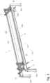
- the tube handling system 1 comprises a supporting frame 2 extending along a longitudinal direction X-X between a first end portion 21 and a second end portion 22.
- the supporting frame 2 is arranged upstream of the working station 102 of the tube working machine 100 along the feeding direction F-F.
- the supporting frame 2 is configured to be installed in the loading station 101 of the tube working machine 100 with the longitudinal direction X-X aligned along the feeding direction F-F and the first end portion 21 oriented toward the working station 102.
- the first end portion 21 is arranged close to the working station 102 along the feeding direction F-F so that the handling systems 1 can load the tube T with one of the tube ends T1 close to the working station 102.
- this reduces the processing idle time (i.e. the time between the end of one process activity and the start of the next one).
- the supporting frame 2 comprises two crossbars 23a, 23b extending parallel to the longitudinal direction X-X between the first and second end potions 21, 22, and two pairs of uprights 24a, 24b, each configured to support a respective crossbar 23a, 23b at a given height form a ground surface (not shown) in a height direction Z-Z.
- the crossbars 23a, 23b and the respective uprights 24a, 24b are spaced apart along a transverse direction Y-Y perpendicular to the longitudinal direction X-X.
- the supporting system 103 is arranged between the crossbars 23a, 23b and the respective uprights 24a, 24b along the transverse direction Y-Y. Therefore, the supporting frame 2 define an internal region 25 extending along the longitudinal, transverse and height direction X-X, Y-Y, Z-Z that is configured to receive the supporting system 103.
- the singularization apparatus 101a is arranged on one side of the supporting system 103 along the transverse direction Y-Y, in particular below one of the crossbars 23a, 23b of the supporting frame 2 in the height direction Z-Z. Therefore, the supporting frame 2 is configured to receive into the internal region 25 also at least part of the singularization apparatus 101a.
- a singularization apparatus is a system configured to isolate a tube from a bundle of tubes.
- the handling system 1 is preferably configured to pick up the tube T to be worked from the singularization apparatus 101a - or, more generally, from a pick-up region P1 -, to move the tube T along the transverse direction Y-Y, and to unload the tube T on the supporting system 103 of the tube working machine 100 - or, more generally, into a unloading region P2.
- the movement performed by the handling system 1 is schematically represented in Figure 5 by arrow A.
- the supporting frame 2 may comprise just one crossbar or more than two crossbars.
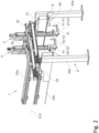
- the handling system 1 comprises a first manipulator 3 mounted on the supporting frame 2 at the first end portion 21.
- the first manipulator 3 has first gripping means 31 adapted to grip the tube T and first driving means 32 configured to move the first gripping means 31 perpendicularly to the longitudinal direction X-X.
- the gripping means 31 are system configured to grip a single tube T to perform the pick-up and handling operations described above. Further details of the gripping mean 31 will be provided in a subsequent part of the description.
- the first driving means 32 are configured to move the first gripping means 31 along a first moving direction Y1-Y1 and a second moving direction Z1-Z1, both perpendicular to the longitudinal direction X-X.
- the first driving means 32 are configured to move the first gripping means in a plane normal to the longitudinal direction X-X.
- the first and second moving direction Y1-Y1, Z1-Z1 are parallel to the transversal and height directions Y-Y, Z-Z, respectively.
- the handling system 1 comprises two second manipulators 4, 5 arranged spaced apart along the longitudinal direction X-X.
- the handling system 1 may comprise only one second manipulator 4, or more than two second manipulators.
- the third and fourth moving direction Y2-Y2, Z2-Z2 are parallel to the transverse and height direction Y-Y, Z-Z, respectively.
- the first and second gripping means 31, 41, 51 are configured to move between the pick-up region P1 (e.g. singularization apparatus 101a) and the unloading region P2 (e.g. supporting system 103) in order to pick up the tube to be worked and to load it into the tube working station of the working machine 100.
- the pick-up region P1 e.g. singularization apparatus 101a
- the unloading region P2 e.g. supporting system 103
- Each second manipulator 4, 5 also comprises third driving means 43, 53 configured to drive the second manipulator 4, 5 to let the second manipulator 4, 5 to slide along the longitudinal direction X-X on the supporting frame 2 with respect to the first manipulator 3.
- the mutual movement of the second manipulators 4, 5 with respect to the first manipulator 3 in the longitudinal direction X-X allows the distance between the first and second gripping means 31, 41, 51 to be adapted to the length of the tube T.
- the first and second manipulators 3, 4, 5 are slidably mounted on the crossbars 23a, 23b of the supporting frame 2.
- the first and second manipulators 3, 4, 5 are arranged between the crossbars 23a, 23b along the transverse direction Y-Y.
- the first and second driving means 32, 42, 52 are preferably configured to move the first and second manipulators 3, 4, 5 along the transverse direction Y-Y and/or along the height direction Z-Z with respect to the crossbars 23a, 23b.
- the first and second driving means 32, 42, 52 comprises brushless motors (not shown) with an integrated encoder (not shown) configured to control the position of the gripping means 31, 41, 51.
- the first and second driving means 32, 42, 52 are two-axis cartesian robots on which the first and second gripping means 31, 41, 51 are mounted to be moved perpendicularly to the longitudinal direction X-X.
- first and second gripping means 31, 41, 51 are shown in figures 3a, 3b and 3c .
- the first and/or second gripping means 31, 41, 51 comprise a main body 34, 44, 54 on which the first/second driving means 32, 42, 52 are configured to act to move the first/second gripping means 41, 51 perpendicularly to the longitudinal direction X-X.
- the first and/or second gripping means 31, 41, 51 further comprise a support element 35, 45, 55 mounted on the main body 34, 44, 54, a pin 36, 46, 56 attached to the support element 35, 45, 55, and pivoting means 37, 47, 57 configured to act on the support element 35, 45, 55.
- the support element 35, 45, 55 is pivotally mounted on the main body 34, 44, 54 around a rotation axis R1-R1, R2-R2, R3-R3 and the pivoting means 37, 47, 57 are configured to drive the support element 35, 45, 55 around the rotation axis R1-R1, R2-R2, R3-R3.
- the support element 35, 45, 55 and the pin 36, 46, 56 extend mainly transversely and parallel to the rotation axis R1-R1, R2-R2, R3-R3, respectively.
- the support element 35, 45, 55 extends transversely, in particular perpendicularly, to the direction of action of gravity (vertical direction Z-Z) between a first extremity portion 35a, 45a, 55a kinematically connected to the pivoting means 37, 47, 57 and a second extremity portion 35b, 45b, 55b on which the pin 36, 46, 56 is mounted.
- the pivoting means 37, 47, 57 dive the support element 35, 45, 55 around the rotation axis R1-R1, R2-R2, R3-R3 in a clamping direction to clamp the supported tube T between the main body 34, 44, 54 and the pin 36, 46, 56.
- the pivoting means 37, 47, 57 pivot the support element 35, 45, 55 around the rotation axis R1-R1, R2-R2, R3-R3 in a release direction opposite to the clamping direction.
- the pivoting means 37, 47, 57 comprises a brushless motor 38, 48, 58 kinematically connected to the support element 35, 45, 55 for driving the support element 35, 45, 55 around the rotation axis R1-R1, R2-R2, R3-R3 in the clamping and release direction of rotation.
- the gripping means 31, 41, 51 described above can be used to clamp tubes T with different cross-section by simply modifying the angle that the support element 35, 45, 55 swivel around the rotation axis R1-R1, R2-R2, R3-R3 to clamp the tube.
- the first gripping means 31 of the first manipulator 3 comprises a roller 33 on which the supported tube T slides upon the motion of the at least one of the second manipulator 4, 5 along the longitudinal direction X-X.
- the roller 33 is arranged on the support element 35, 45, 55, preferably extending between the first extremity portion 35a, 45a, 55a the second extremity portion 35b, 45b, 55b.
- the roller 33 has a rolling axis R-R that, preferably, is oriented along the direction that connects the first extremity portion 35a, 45a, 55a the second extremity portion 35b, 45b, 55b.
- the handling system 1 is configured to measure the length of the handled tube T.
- the handling system 1 comprises a measuring unit 6 configured to measure the extension of the tube along the axial direction A-A when the tube is supported by the first and second gripping means 31, 41, 51.
- the measuring unit 6 comprises a first measuring sensor 61 mounted on at least one of the second manipulators 4, 5 and configured to detect a first tube end T1.
- the first measuring sensor 61 is preferably mounted on the second gripping means 41 of at least one of the second manipulators 4.
- the first measuring sensor 61 is arranged on the main body 34, 44, 54 of the gripping means 41 so as to face the supported tube T.
- the first measuring sensors 61 is a optoelectronic sensor, particular based on triangulation, i.e. a sensor able to sense the object that is some centimeters far away, or flying time sensor based.
- a sensor able to sense the object that is some centimeters far away, or flying time sensor based.
- the second manipulator 4, 5, on which the first measuring sensor 61 is arranged moves along the axial direction of the tube till the latter detects the first tube end T1.
- the measuring unit 6 comprises a second measuring sensor 62 mounted on the supporting frame 2, in particular at the first end portion 21, and configured to detect a second tube end T2 opposite to the first one T1.
- the second measuring sensor 62 is, for example, a optoelectronic sensor, in particular a reflective optoelectronic sensor, or triangulation or flying time sensor.
- the tube T is moved by the second manipulator 4, 5 along the longitudinal direction X-X towards the first end portion 21 until the second measuring sensor 62 detects the second tube end T2.
- the measure of the length of the tube is then obtained by calculating the difference between the positions of the first and second tube ends T1, T2.
Landscapes
- Engineering & Computer Science (AREA)
- Physics & Mathematics (AREA)
- Optics & Photonics (AREA)
- Mechanical Engineering (AREA)
- Plasma & Fusion (AREA)
- Manipulator (AREA)
Priority Applications (3)
| Application Number | Priority Date | Filing Date | Title |
|---|---|---|---|
| EP23186119.6A EP4494802A1 (fr) | 2023-07-18 | 2023-07-18 | Système de manipulation de tube pour machine de travail de tube et machine de travail de tube laser comprenant ledit système de manipulation de tube |
| PCT/EP2024/070293 WO2025017081A1 (fr) | 2023-07-18 | 2024-07-17 | Système de manipulation de tube pour une machine de travail de tube et machine de travail de tube laser comprenant ledit système de manipulation de tube |
| CN202480047863.6A CN121548480A (zh) | 2023-07-18 | 2024-07-17 | 用于管加工机器的管处理系统和包括所述管处理系统的激光管加工机器 |
Applications Claiming Priority (1)
| Application Number | Priority Date | Filing Date | Title |
|---|---|---|---|
| EP23186119.6A EP4494802A1 (fr) | 2023-07-18 | 2023-07-18 | Système de manipulation de tube pour machine de travail de tube et machine de travail de tube laser comprenant ledit système de manipulation de tube |
Publications (1)
| Publication Number | Publication Date |
|---|---|
| EP4494802A1 true EP4494802A1 (fr) | 2025-01-22 |
Family
ID=87418740
Family Applications (1)
| Application Number | Title | Priority Date | Filing Date |
|---|---|---|---|
| EP23186119.6A Withdrawn EP4494802A1 (fr) | 2023-07-18 | 2023-07-18 | Système de manipulation de tube pour machine de travail de tube et machine de travail de tube laser comprenant ledit système de manipulation de tube |
Country Status (3)
| Country | Link |
|---|---|
| EP (1) | EP4494802A1 (fr) |
| CN (1) | CN121548480A (fr) |
| WO (1) | WO2025017081A1 (fr) |
Citations (4)
| Publication number | Priority date | Publication date | Assignee | Title |
|---|---|---|---|---|
| US4548537A (en) * | 1982-05-17 | 1985-10-22 | Mitsui Engineering & Shipbuilding Co., Ltd. | Apparatus for taking up rod type materials |
| DD229974A1 (de) * | 1984-12-20 | 1985-11-20 | Warnowwerft Warnemuende Veb | Vorrichtung zum vereinzeln von rohren |
| EP3950218A1 (fr) * | 2020-08-03 | 2022-02-09 | F.O.M. Industrie S.r.l. | Centre de travail pour traiter des barres de section, en particulier en aluminium, en alliages légers, en pvc ou analogues |
| US20220063044A1 (en) * | 2019-01-08 | 2022-03-03 | F.O.M. Industrie S.R.L. | Work centre to process section bars, in particular made of aluminium, light alloys, pvc or the like |
-
2023
- 2023-07-18 EP EP23186119.6A patent/EP4494802A1/fr not_active Withdrawn
-
2024
- 2024-07-17 WO PCT/EP2024/070293 patent/WO2025017081A1/fr active Pending
- 2024-07-17 CN CN202480047863.6A patent/CN121548480A/zh active Pending
Patent Citations (4)
| Publication number | Priority date | Publication date | Assignee | Title |
|---|---|---|---|---|
| US4548537A (en) * | 1982-05-17 | 1985-10-22 | Mitsui Engineering & Shipbuilding Co., Ltd. | Apparatus for taking up rod type materials |
| DD229974A1 (de) * | 1984-12-20 | 1985-11-20 | Warnowwerft Warnemuende Veb | Vorrichtung zum vereinzeln von rohren |
| US20220063044A1 (en) * | 2019-01-08 | 2022-03-03 | F.O.M. Industrie S.R.L. | Work centre to process section bars, in particular made of aluminium, light alloys, pvc or the like |
| EP3950218A1 (fr) * | 2020-08-03 | 2022-02-09 | F.O.M. Industrie S.r.l. | Centre de travail pour traiter des barres de section, en particulier en aluminium, en alliages légers, en pvc ou analogues |
Also Published As
| Publication number | Publication date |
|---|---|
| WO2025017081A1 (fr) | 2025-01-23 |
| CN121548480A (zh) | 2026-02-17 |
Similar Documents
| Publication | Publication Date | Title |
|---|---|---|
| CN111975250B (zh) | 工件旋转装置和机器人系统 | |
| JP3300609B2 (ja) | 熱交換器の熱交換用チューブ組立て装置および組立て方法 | |
| KR101488540B1 (ko) | 물품 처리 장치, 시스템 및 방법 | |
| EP0950443B1 (fr) | Machine à cintrer des tubes | |
| US7967354B2 (en) | Mixed size product handling end of arm tool | |
| KR100522653B1 (ko) | 로봇 핸들링 장치 | |
| JP2002336994A (ja) | 搬送装置及び溶接装置 | |
| JP2002145448A (ja) | 反転積み重ね装置 | |
| EP3950218B1 (fr) | Centre de travail pour traiter des barres de section, en particulier en aluminium, en alliages légers, en pvc ou analogues | |
| KR20150010342A (ko) | 파이프 이송장치 | |
| US12485538B2 (en) | Method and system for determining a workplace loading location in a CNC machine with a robotic arm | |
| EP4494802A1 (fr) | Système de manipulation de tube pour machine de travail de tube et machine de travail de tube laser comprenant ledit système de manipulation de tube | |
| CN111071559A (zh) | 一种打包装置 | |
| KR20210096469A (ko) | 다목적 피스톤 그리퍼 및 이를 구비한 로봇 매니퓰레이터 | |
| CN112888533A (zh) | 工件自动搬运机 | |
| EP3950217B1 (fr) | Procédé de configuration d'un poste de travail pour traiter des barres de section, fabriquées en particulier en aluminium, en alliages légers, en pvc ou analogues | |
| CN215094805U (zh) | 环形切方制造岛 | |
| CN219361459U (zh) | 双夹爪夹取装置 | |
| US20010027152A1 (en) | Machining centers | |
| CN215511756U (zh) | 线形切方制造岛 | |
| US7131309B2 (en) | Bending system | |
| CN215511759U (zh) | 单根固定立式开方系统 | |
| JPH1076492A (ja) | 部品挿入装置および部品挿入方法 | |
| CN209160917U (zh) | 下料机构及棒料加工装置 | |
| US5950479A (en) | Process and apparatus for moving sheet-metal to and from a bending unit |
Legal Events
| Date | Code | Title | Description |
|---|---|---|---|
| PUAI | Public reference made under article 153(3) epc to a published international application that has entered the european phase |
Free format text: ORIGINAL CODE: 0009012 |
|
| STAA | Information on the status of an ep patent application or granted ep patent |
Free format text: STATUS: THE APPLICATION HAS BEEN PUBLISHED |
|
| AK | Designated contracting states |
Kind code of ref document: A1 Designated state(s): AL AT BE BG CH CY CZ DE DK EE ES FI FR GB GR HR HU IE IS IT LI LT LU LV MC ME MK MT NL NO PL PT RO RS SE SI SK SM TR |
|
| STAA | Information on the status of an ep patent application or granted ep patent |
Free format text: STATUS: THE APPLICATION IS DEEMED TO BE WITHDRAWN |
|
| 18D | Application deemed to be withdrawn |
Effective date: 20250723 |