EP4494824A1 - Outil portatif - Google Patents
Outil portatif Download PDFInfo
- Publication number
- EP4494824A1 EP4494824A1 EP24188982.3A EP24188982A EP4494824A1 EP 4494824 A1 EP4494824 A1 EP 4494824A1 EP 24188982 A EP24188982 A EP 24188982A EP 4494824 A1 EP4494824 A1 EP 4494824A1
- Authority
- EP
- European Patent Office
- Prior art keywords
- housing
- ejection opening
- guide rail
- longitudinal
- working device
- Prior art date
- Legal status (The legal status is an assumption and is not a legal conclusion. Google has not performed a legal analysis and makes no representation as to the accuracy of the status listed.)
- Pending
Links
Images


Classifications
-
- B—PERFORMING OPERATIONS; TRANSPORTING
- B27—WORKING OR PRESERVING WOOD OR SIMILAR MATERIAL; NAILING OR STAPLING MACHINES IN GENERAL
- B27G—ACCESSORY MACHINES OR APPARATUS FOR WORKING WOOD OR SIMILAR MATERIALS; TOOLS FOR WORKING WOOD OR SIMILAR MATERIALS; SAFETY DEVICES FOR WOOD WORKING MACHINES OR TOOLS
- B27G3/00—Arrangements for removing bark-zones, chips, waste, or dust, specially designed for use in connection with wood-working machine or in wood-working plants
-
- B—PERFORMING OPERATIONS; TRANSPORTING
- B27—WORKING OR PRESERVING WOOD OR SIMILAR MATERIAL; NAILING OR STAPLING MACHINES IN GENERAL
- B27B—SAWS FOR WOOD OR SIMILAR MATERIAL; COMPONENTS OR ACCESSORIES THEREFOR
- B27B17/00—Chain saws; Equipment therefor
-
- B—PERFORMING OPERATIONS; TRANSPORTING
- B27—WORKING OR PRESERVING WOOD OR SIMILAR MATERIAL; NAILING OR STAPLING MACHINES IN GENERAL
- B27B—SAWS FOR WOOD OR SIMILAR MATERIAL; COMPONENTS OR ACCESSORIES THEREFOR
- B27B17/00—Chain saws; Equipment therefor
- B27B17/0083—Attachments for guiding or supporting chain saws during operation
-
- B—PERFORMING OPERATIONS; TRANSPORTING
- B27—WORKING OR PRESERVING WOOD OR SIMILAR MATERIAL; NAILING OR STAPLING MACHINES IN GENERAL
- B27B—SAWS FOR WOOD OR SIMILAR MATERIAL; COMPONENTS OR ACCESSORIES THEREFOR
- B27B17/00—Chain saws; Equipment therefor
- B27B17/02—Chain saws equipped with guide bar
-
- B—PERFORMING OPERATIONS; TRANSPORTING
- B27—WORKING OR PRESERVING WOOD OR SIMILAR MATERIAL; NAILING OR STAPLING MACHINES IN GENERAL
- B27B—SAWS FOR WOOD OR SIMILAR MATERIAL; COMPONENTS OR ACCESSORIES THEREFOR
- B27B17/00—Chain saws; Equipment therefor
- B27B17/08—Drives or gearings; Devices for swivelling or tilting the chain saw
Definitions
- the invention relates to a portable working device of the type specified in the preamble of claim 1.
- Portable tools such as motor chain saws, are known which have an ejection opening for removing chips from the chain wheel space into the surrounding area.
- Such ejection openings are usually formed on the underside of the portable tool, i.e. below the load side of the saw chain.
- a tool also comprises an ejection opening on the front of the tool. The saw chain is guided from the chain wheel space into the surrounding area via the ejection opening formed on the front.
- the invention is based on the object of creating a portable working device of the generic type which allows good chip removal.
- the portable working device comprises a housing, a drive motor arranged in the housing, a guide rail with a longitudinal central axis and a saw chain, wherein the drive motor drives the saw chain guided in a guide groove of the guide rail in a rotating manner via a drive sprocket, wherein a longitudinal plane of the guide rail is spanned by the guide groove, wherein the housing comprises a base housing and a sprocket cover, wherein the base housing and the sprocket cover delimit a sprocket space, wherein the housing has a front side and a rear side, wherein the guide rail protrudes from the housing at the front, wherein the housing has a first longitudinal side and a second longitudinal side, via which the front and the rear of the housing are connected, wherein in particular the housing has a top side and a bottom side, wherein an ejection opening for ejecting sawdust from the sprocket space into the outside environment is formed on the housing, wherein the ejection opening
- the first section of the ejection opening has a height h which, when projected in the direction perpendicular to the longitudinal plane onto the longitudinal plane of the guide rail, is at least 5 mm, in particular at least 7.5 mm, preferably at least 10 mm.
- the ejection opening on the side of the housing allows the chips to be removed particularly well. This is particularly advantageous for portable tools with short guide rails, such as a wood cutter. With such tools, the operator often uses the entire length of the guide rail and plunges it into the workpiece with its entire length. If the front of the housing hits the workpiece, this can lead to a blockage of an ejection opening on the front of the housing. Chip removal is no longer possible in an optimal manner.
- the ejection opening on the side means that the chips can be conveyed to the outside environment through the ejection opening even when the front of the wood cutter is resting on the workpiece.
- the ejection opening on the side has also proven to be particularly advantageous for longitudinal cuts in wood. The sawdust that forms during longitudinal cuts is particularly long, which makes it difficult to remove these chips.
- the ejection opening on the side of the housing has proven to be particularly advantageous.
- the ejection opening is at least partially formed by a recess on the sprocket cover.
- the chips are thus removed from the sprocket space into the outside environment, in particular via the sprocket cover.
- the guide rail has a longitudinal upper side and a longitudinal lower side opposite the longitudinal upper side in relation to the longitudinal center axis, with the ejection opening being arranged in the region of the longitudinal upper side of the guide rail. The ejection opening is thus arranged on the slack side of the saw chain.
- the first section of the ejection opening has a length measured in the direction of the longitudinal center axis that is greater than the height of the ejection opening.
- the first section of the ejection opening is essentially rectangular in shape when viewed towards the sprocket cover, perpendicular to the longitudinal plane of the guide rail.
- the first section of the ejection opening is thus sufficiently large to enable the chips to be ejected over the long side of the housing.
- the ejection opening can also have a shape, for example the ejection opening can open in the shape of a triangle in the direction of the guide rail.
- the ejection opening is designed such that the first section of the ejection opening extends in the direction of the longitudinal center axis of the guide rail from a first end to a second end, wherein the ejection opening is designed such that, when viewed towards the sprocket cover perpendicular to the longitudinal plane of the guide rail, the saw chain between the first end and the second end of the first section of the ejection opening is covered over at least 50%, in particular over at least 65%, in particular over at least 80% of the length, most particularly over the complete extension of the first section of the ejection opening by the housing, in particular by the sprocket cover.
- the cover area projects beyond the saw chain by at least 1.0 mm in the direction away from the longitudinal center axis of the guide rail, perpendicular to the longitudinal center axis of the guide rail and parallel to the longitudinal plane of the guide rail.
- the cover area projects beyond the saw chain by at least 1.0 mm in the direction away from the longitudinal center axis of the guide rail in the direction perpendicular to the longitudinal plane on the longitudinal plane of the guide rail.
- the housing tapers, in particular conically, towards the front of the housing, wherein in the second section of the ejection opening at the first end of the ejection opening a further recess is provided on the housing, in particular on the sprocket cover, which exposes the saw chain when viewed towards the sprocket cover perpendicular to the longitudinal plane of the guide rail.
- the conical design of the housing towards the front of the housing enables a slim design of the housing at the front. This ensures high accessibility to the workpiece by the work tool. This is particularly advantageous when delimbing trees.
- the further recess enlarges the ejection opening, in particular at the front of the housing. This compensates for the narrowing of the ejection opening resulting from the conicity of the housing towards the front. The ejection opening is therefore large enough to ensure sufficient chip ejection.
- the ejection opening comprises a second section which is formed on the front of the housing.
- the chips can thus exit from the sprocket space via the first section of the ejection opening on the first longitudinal side of the housing and via the second section of the ejection opening on the front of the housing.
- the second section of the ejection device preferably points towards the front of the working device the longitudinal center axis has a minimum width measured perpendicular to the longitudinal plane of the guide rail.
- the minimum width of the second section of the ejection opening corresponds to at least 10%, preferably at least 20%, preferably at least 30% of the width of the housing at the front measured perpendicular to the longitudinal plane of the guide rail.
- the minimum width of the second section of the ejection opening is in particular not greater than 50% of the width of the housing at the front.
- the working device particularly preferably has a further ejection opening, wherein the further ejection opening is preferably formed on the underside of the housing.
- the drive motor is an electric motor.
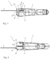
- Fig. 1 an embodiment of a portable, hand-held working device 1 according to the invention is shown.
- the term "portable” is to be understood in such a way that when the working device 1 is being used as intended, the working device 1 is carried by the operator.
- the working device 1 is designed as a wood cutter.
- a wood cutter is preferably intended for cutting branches and small woody plants. The preferred use of a wood cutter is in particular for pruning trees.
- the working device 1 can also be designed as a motor chainsaw.
- the working device 1 can also have a shaft and be designed, for example, as a pole pruner, as a tree care saw or the like.
- the working device 1 comprises a housing 2.
- the working device 1 comprises a drive motor 3.
- the drive motor 3 is arranged in the housing 2.
- the working device 1 also comprises a saw chain 6.
- the saw chain 6 is driven by the drive motor 3.
- the saw chain 6 is driven in a rotating manner in a guide groove of a guide rail 4.
- the drive motor 3 drives a drive sprocket (not shown in detail) via its drive shaft, which in turn drives the saw chain 6 in a rotating manner around the guide rail 4 in a running direction 33.
- the housing 2 comprises a base housing 7 and a sprocket cover 8.
- the sprocket cover 8 is arranged on the base housing 7 and covers the drive sprocket.
- the guide rail has a deflection area 34 facing away from the housing 2.
- the saw chain 6 has a first strand 35, a so-called load strand, which extends in the running direction 33 from the deflection area 34 to the drive sprocket.
- the saw chain 6 has a second strand 36, a so-called slack strand, which moves from the drive sprocket to the deflection area 34.
- the drive motor 3 is designed as an electric motor in the exemplary embodiment.
- the working device 1 comprises in particular at least one first battery pack 41, which is only shown schematically.
- the first battery pack 41 is intended to supply the drive motor 3 with electrical energy.
- the working device 1 comprises in particular a second battery pack 42, which is only shown schematically.
- the second battery pack 42 is intended to supply the drive motor 3 with electrical energy.
- the working device 1, in particular the drive motor 3 of the working device 1, can in particular also be operated using only one of the two battery packs 41, 42.
- the two battery packs 41, 42 are connected in series in particular.
- the drive motor 3 can also be designed as an internal combustion engine.
- the guide rail 4 comprises a longitudinal central axis 5.
- the working device 1 further comprises a longitudinal plane 31 which is spanned by the guide groove of the guide rail 4.
- the longitudinal central axis 5 of the guide rail 4 lies in the longitudinal plane 31.
- the longitudinal central axis 5 runs centrally through the guide rail 4, whereby the guide rail 4 is divided into two approximately equal parts by the longitudinal central axis 5 when viewed perpendicular to the longitudinal plane 31 of the guide rail 4.
- the guide rail 4 further comprises a transverse plane 32.
- the transverse plane 32 is aligned orthogonally to the longitudinal plane 31 of the guide rail 4.
- the longitudinal central axis 5 lies in the transverse plane 32.
- the housing 2 of the working device 1 comprises a front end 43 and a rear end 44.
- the front end 43 corresponds to a front side 10 of the housing 2.
- the guide rail 4 is fixed to the housing 2 and protrudes from the housing 2 at the front side 10.
- the rear end 44 corresponds to the rear side 11 of the housing 2.
- the rear end 44 is in the present embodiment by the battery packs 41, 42. In an alternative embodiment, the rear end 44 can also be formed by a handle of the working device 1.
- the housing 2 has a first longitudinal side 12 and a second longitudinal side 13 ( Fig. 4 to 6 ).
- the first long side 12 and the second long side 13 are connected to one another via the front side 10 and the back side 11 of the housing 2.
- the housing 2 has a top side 14 and a bottom side 15.
- the first longitudinal side 12 and the second longitudinal side 13 are connected to one another via the top side 14 and the bottom side 15.
- the first longitudinal side 13 and the second longitudinal side 14 extend essentially in the direction of the longitudinal plane 31 of the guide rail 4.
- top and bottom refer to an orientation of the working device 1 in which the longitudinal center axis 5 of the guide rail 4 lies in a horizontal plane 45 and the longitudinal plane 31 of the guide rail 4 is aligned perpendicular to the horizontal plane 45.
- Such an orientation of the working device 1 is in Fig. 2 shown.
- the first run 35 of the saw chain 6 is arranged on a longitudinal underside 17 of the guide rail 4 and the second run 36 of the saw chain 6 is arranged on a longitudinal upper side 16 of the guide rail 4.
- the viewing direction onto the longitudinal upper side 16 of the guide rail 4 naturally also corresponds to the viewing direction onto the upper side 14 of the housing 2.
- Such a viewing direction is shown in Fig. 6
- the viewing direction of the longitudinal underside 17 of the guide rail 4 also corresponds to the viewing direction of the underside 15 of the housing 2.
- Such a viewing direction is shown, for example, in Fig. 5 shown.
- the working device 1 comprises a first handle 47 for supporting a hand of the operator.
- the first handle 47 is formed on a handle housing 49.
- the handle housing 49 is part of the housing 2.
- the working device 1 comprises a control element 50 for actuating the drive motor 3.
- the control element 50 is assigned to the first handle 47, ie that in the intended operation of the Working device 1, the operator actuates the control element 50 with the hand that rests on the first handle 47.
- the working device 1 comprises a preferably mechanical locking element 51.
- the locking element 51 is preferably designed as a locking lever.
- the locking element 51 is designed to lock the control element 50 in a locking position, preferably mechanically, and to release it in an operating position. If the operator wants to actuate the control element 50, he must first unlock the control element 50 by actuating the locking element 51. The operator can then actuate the control element 50 and control the drive motor 3.
- the working device 1 comprises a second handle 48 in addition to the first handle 47.
- the second handle 48 serves to support the operator's second hand and enables the operator to better guide the working device 1.
- the second handle 48 is provided on the housing 2, in particular in the area of the drive motor 3.
- the working device 1 comprises a fixing device 37 for fastening the guide rail 4.
- the guide rail 4 In an operating state of the fixing device 37, the guide rail 4 is held clamped to the housing 2.
- the guide rail 4 In a released state of the fixing device 37, the guide rail 4 can be moved in the direction of the longitudinal center axis 5 relative to the housing 2.
- the guide rail 4 can be pushed away from the housing 2 in the direction of its longitudinal center axis 5, as a result of which the saw chain 6 can be tensioned.
- the chain wheel cover 8 is part of the fixing device 37.
- the guide rail 4 In the fixed state of the fixing device 37, the guide rail 4 is held clamped between the chain wheel cover 8 and the base housing 7.
- a nut 38 is provided for fastening the chain wheel cover 8 to the housing 2.
- the nut 38 is to be screwed onto a bolt 39 which is firmly connected to the housing 2.
- the chain wheel cover 8 is pressed against the guide rail 4 via the nut 38, and the guide rail 4 is pressed against the base housing 7.
- the chain wheel cover 8 covers the sprocket.
- the sprocket cover 8 is provided in particular on the first longitudinal side 12 of the housing 2.
- the working device 1 comprises an ejection opening 20 for ejecting sawdust from the sprocket space 9 into an external environment 30.
- the sprocket space 9 is delimited by the base housing 7 and the sprocket cover 8.
- the ejection opening 20 is formed as a through-opening in the housing 2, in particular in the sprocket cover 8, whereby chips can pass from the sprocket space 9 into the external environment 30 via the ejection opening 20.
- the drive sprocket is arranged in the sprocket space 9.
- the saw chain 6 enters the sprocket space in the region of the first run 35, is deflected via the drive sprocket and then exits the sprocket space 9 back into the external environment 30 in the region of the second run 36.
- the ejection opening 20 is formed at least partially on the first longitudinal side 12 of the housing 2, whereby the chips are conveyed out of the chain wheel space 9 via the first longitudinal side 12 of the housing 2.
- the ejection opening 20 is arranged in the region of the second run 36. In other words, the ejection opening 20 is located in the region of the guide rail 4, from which the saw chain 6 runs out of the housing 2.
- the ejection opening 20 is arranged in the region of the longitudinal upper side 16 of the guide rail 4.
- the ejection opening is arranged in the region of the first run 35, i.e. in the region of the longitudinal lower side 17 of the guide rail 4.
- a further ejection opening 40 is provided.
- the further ejection opening 40 is provided on the underside 15 of the housing 2, in particular the chain wheel cover 8.
- the further ejection opening 40 is formed in the area of the first run 35.
- the further ejection opening 20 is located in the area of the guide rail into which the saw chain 6 runs in the chain wheel space towards the drive chain wheel.
- the further ejection opening 40 is only formed on the underside 15 of the housing 2.
- the further ejection opening 40 is also formed at least partially, in particular completely, on the first longitudinal side 12 of the housing 2.
- the ejection opening 20 has a first section 21 and a second section 22.
- the first section 21 of the ejection opening 20 is formed on the first longitudinal side 12 of the housing 2.
- the second section 22 is formed on the front 10 of the housing 2.
- the first section 21 and the second section 22 merge directly into one another, whereby the two sections 21, 22 form a single opening, namely the ejection opening 20.
- the saw chain 6 is guided outwards from the sprocket space 9 via the second section 22 of the ejection opening 20.
- the ejection opening 20 is essentially formed by a recess 23 on the sprocket cover 8.
- the first section 21 of the ejection opening 20 is formed only by the recess 23 in the sprocket cover 8.
- the second section 22 of the ejection opening 23 is at least partially formed by the recess 23 of the sprocket cover 8.
- the second section 22 of the ejection opening 23 is also at least partially formed by a recess on the front side 10 of the base housing 7.
- the first section 21 of the ejection opening 20 has a substantially rectangular contour in the direction of the sprocket cover 8 perpendicular to the longitudinal plane 31.
- the first section 21 of the ejection opening 20 has a rectangular contour in the projection in the direction of the sprocket cover perpendicular to the longitudinal plane 31 onto the longitudinal plane 31.
- Other Contours that form a sufficiently large opening for the removal of chips are conceivable as an alternative.
- the first section 21 has a height h measured parallel to the longitudinal plane 31 and perpendicular to the longitudinal center axis 5 of the guide rail 4. In other words, the height h is measured perpendicular to the transverse plane 32.
- the height h of the first section 21 of the ejection opening 20 is at least 5 mm, in particular at least 7.5 mm, preferably at least 10 mm.
- the height h of the first section 21 of the ejection opening 20 corresponds to a distance between a lower edge 61 of the ejection opening 20 and an upper edge 62 of the ejection opening 20.
- the lower edge 61 of the ejection opening 20 is formed by the sprocket cover 8.
- the upper edge 62 is formed on the base housing 7 in the present embodiment.
- the ejection opening 20 is thus limited at the top by the housing 2.
- the working device 1 designed as a tree cutter comprises a lubricant tank which forms the upper edge 62 of the ejection opening 20.
- the lubricant tank is part of the housing 2, in particular of the base housing 7.
- the ejection opening 20 is limited at the top by the lubricant tank.
- the first section 21 of the ejection opening 20 extends from a first end 24 in the direction of the longitudinal center axis 5 to a second end 25.
- the first end 24 is formed at the front end 43 of the housing 2, i.e. at the front 10 of the housing 2.
- the second end 25 of the section 21 is formed by a raised edge 27 on the recess 23 of the sprocket cover 8.
- the first section 21 of the ejection opening 20 has a length 1 measured in the direction of the longitudinal center axis 5, which corresponds to the distance between the first end 24 of the first section 21 and the second end 25 of the first section 21.
- the length l of the first section 21 of the ejection opening 20 is greater in the exemplary embodiment than the height h of the first section 21 of the ejection opening 20.
- the length l of the first section 21 is at least 10 mm, preferably at least 15 mm.
- the housing 2, in particular the sprocket cover 8 has a cover area 28 between the first end 24 of the first section 21 and the second end 25 of the first section 21.
- the saw chain 6 is covered by the housing 2, in particular by the sprocket cover 8, when viewed towards the sprocket cover 8, perpendicular to the longitudinal plane 31 of the guide rail 4.
- the lower edge 61 of the first section 21 of the ejection opening 20 is formed perpendicular to the longitudinal plane 31 above the longitudinal upper side 16 of the guide rail 4, in particular above the saw chain 6, when viewed towards the sprocket cover 8.
- the ejection opening 20 has a height h 1 in the cover area 28 of the first section 21 measured parallel to the longitudinal plane 31 and perpendicular to the longitudinal center axis 5 of the guide rail 4.
- the height h 1 of the ejection opening 20 in the cover area 28 is measured perpendicular to the transverse plane 32.
- the height h 1 of the ejection opening 20 in the cover area 28 is at least 5 mm, in particular at least 7.5 mm, preferably at least 10 mm.
- the height h 1 of the ejection opening 20 in the cover area 28 is at most 30 mm, in particular at most 20 mm, most particularly at most 15 mm.
- the housing 2, in particular the sprocket cover 8 has an open area 29 between the first end 24 of the first section 21 and the second end 25 of the first section 21.
- the open area 29 is formed by a further recess 26 of the sprocket cover 8.
- the saw chain 6 is exposed through the further recess 26 of the sprocket cover 8 as viewed towards the sprocket cover 8, perpendicular to the longitudinal plane 31 of the guide rail 4.
- the lower edge 61 of the first section 21 of the ejection opening 20 is formed as viewed towards the sprocket cover 8, perpendicular to the longitudinal plane 31 below an upper side 18 of the saw chain 6 facing away from the guide rail 4.
- the open area 29 begins directly at the front 10 of the housing 2, in particular the sprocket cover 8.
- the open area 29 extends from the front 10 of the housing 2 to the cover area 28 over a 5 of the guide rail 4 measured length b.
- the length b of the open area 29 is in particular less than 5 mm.
- no further recess 26 is provided.
- the housing 2, in particular the chain wheel cover 8, does not comprise an open area 29, but only a cover area 28.
- the ejection opening 20 is designed such that, in the direction of view towards the chain wheel cover 8 perpendicular to the longitudinal plane 31 of the guide rail 4, the saw chain 6 between the first end 24 and the second end 25 of the first section 21 of the ejection opening 20 is covered over at least 50%, in particular over at least 65%, preferably over at least 80% of the length l of the first section 21 of the ejection opening 20 by the housing 2, in particular by the chain wheel cover 8.
- a length c of the cover area 28 measured in the direction of the longitudinal center axis 5 of the guide rail 4 is at least 50%, in particular at least 65%, preferably at least 80% of the length l of the first section 21 of the ejection opening 20.
- the distance d between the lower edge 61 of the ejection opening 20 in the first section 21 and the upper side 18 of the saw chain 6 is at least 1 mm, preferably at least 2 mm, in particular at least 3 mm.
- the second section 22 of the ejection opening 20 has a minimum width b measured perpendicular to the longitudinal plane 31 of the guide rail 4 when viewed towards the front 10 of the implement 1 in the direction of the longitudinal center axis 5.
- the minimum width b is at least 10%, preferably at least 20%, preferably at least 30% of the width a of the housing 2 measured perpendicular to the longitudinal plane 31 of the guide rail 4 on the front 10 in the area of the ejection opening 20.
- the width a of the housing 2 corresponds to the distance between the first longitudinal side 12 and the second longitudinal side 13 on the front 10 of the housing 2 in the area of the ejection opening 20.
- the minimum width b of the second section 22 of the ejection opening 20 is at least 10 mm, preferably at least 12.5 mm, in particular at least 15 mm.
- the height e of the second section 22 of the ejection opening 20 measured perpendicular to the transverse plane 32 is at least 10 mm, preferably at least 15 mm, in particular at least 20 mm.
- the housing 2 tapers in the area of the ejection opening 20 towards the front side 10 of the housing 2.
- the housing 2 has in particular a conicity 63 in the area of the ejection opening 20.
- the housing 2 tapers in the area of the ejection opening 20 conically towards the front side 10 of the housing 2.
- the further recess 26 in the first section 21 of the ejection opening 20 at the first end 24 of the ejection opening 20 leads to an increase in the minimum width b of the second section 22 of the ejection opening 20 ( Fig. 4 ).
Landscapes
- Life Sciences & Earth Sciences (AREA)
- Engineering & Computer Science (AREA)
- Mechanical Engineering (AREA)
- Wood Science & Technology (AREA)
- Forests & Forestry (AREA)
- Sawing (AREA)
Applications Claiming Priority (1)
| Application Number | Priority Date | Filing Date | Title |
|---|---|---|---|
| DE102023119005.9A DE102023119005A1 (de) | 2023-07-18 | 2023-07-18 | Tragbares Arbeitsgerät |
Publications (1)
| Publication Number | Publication Date |
|---|---|
| EP4494824A1 true EP4494824A1 (fr) | 2025-01-22 |
Family
ID=91953823
Family Applications (1)
| Application Number | Title | Priority Date | Filing Date |
|---|---|---|---|
| EP24188982.3A Pending EP4494824A1 (fr) | 2023-07-18 | 2024-07-16 | Outil portatif |
Country Status (4)
| Country | Link |
|---|---|
| US (1) | US20250026039A1 (fr) |
| EP (1) | EP4494824A1 (fr) |
| CN (1) | CN119328855A (fr) |
| DE (1) | DE102023119005A1 (fr) |
Families Citing this family (1)
| Publication number | Priority date | Publication date | Assignee | Title |
|---|---|---|---|---|
| WO2023133255A1 (fr) * | 2022-01-06 | 2023-07-13 | Milwaukee Electric Tool Corporation | Scie à chaîne sans fil compacte à forte puissance |
Citations (2)
| Publication number | Priority date | Publication date | Assignee | Title |
|---|---|---|---|---|
| DE19753360A1 (de) * | 1997-12-02 | 1999-06-10 | Stihl Maschf Andreas | Schneidgarnitur mit einem Kettenraddeckel |
| US20020073551A1 (en) * | 2000-11-17 | 2002-06-20 | Steven Goodwin | Chain saw - oil cap |
Family Cites Families (4)
| Publication number | Priority date | Publication date | Assignee | Title |
|---|---|---|---|---|
| US5718050A (en) * | 1996-03-08 | 1998-02-17 | Technic Tool Corporation | Pruning cutter |
| DE19619081B4 (de) * | 1996-05-13 | 2010-01-21 | Fa. Andreas Stihl | Schneidkopf für einen Hochentaster |
| JP6137467B2 (ja) * | 2013-04-25 | 2017-05-31 | 日立工機株式会社 | チェーンソー |
| DE102014004526A1 (de) * | 2014-03-27 | 2015-10-01 | Andreas Stihl Ag & Co. Kg | Handgeführtes Arbeitsgerät |
-
2023
- 2023-07-18 DE DE102023119005.9A patent/DE102023119005A1/de active Pending
-
2024
- 2024-07-16 EP EP24188982.3A patent/EP4494824A1/fr active Pending
- 2024-07-16 US US18/774,566 patent/US20250026039A1/en active Pending
- 2024-07-17 CN CN202410956734.0A patent/CN119328855A/zh active Pending
Patent Citations (2)
| Publication number | Priority date | Publication date | Assignee | Title |
|---|---|---|---|---|
| DE19753360A1 (de) * | 1997-12-02 | 1999-06-10 | Stihl Maschf Andreas | Schneidgarnitur mit einem Kettenraddeckel |
| US20020073551A1 (en) * | 2000-11-17 | 2002-06-20 | Steven Goodwin | Chain saw - oil cap |
Also Published As
| Publication number | Publication date |
|---|---|
| CN119328855A (zh) | 2025-01-21 |
| DE102023119005A1 (de) | 2025-01-23 |
| US20250026039A1 (en) | 2025-01-23 |
Similar Documents
| Publication | Publication Date | Title |
|---|---|---|
| EP3792008B1 (fr) | Appareil de travail portatif doté d'un outil | |
| DE10036458B4 (de) | Staubfangvorrichtung für eine Kreissäge | |
| EP0267973B1 (fr) | Scie motorisée, en particulier scie entraînée par un moteur électrique | |
| DE112013006573B4 (de) | Handgehaltene elektrische Schneidvorrichtung | |
| EP2937166B1 (fr) | Appareil de travail portatif | |
| EP4234160B1 (fr) | Système de guidage doté d'une machine-outil portative et rails de guidage | |
| DE102010040706A1 (de) | Schutzsystem für eine elektrische Säge | |
| EP4494824A1 (fr) | Outil portatif | |
| DE102005053126A1 (de) | Messerbalken einer durch einen Motor angetriebenen Heckenschere | |
| EP0328922A2 (fr) | Jeu de transformation pour une scie circulaire pour travail manuel | |
| DE102010021523B4 (de) | Wippkreissäge | |
| EP1466690A1 (fr) | Scie sauteuse en forme de sabre avec dispositif d'ajustage pour un guide | |
| DE102023133200A1 (de) | Staubschutzvorrichtung für eine Kettensäge | |
| DE19631031B4 (de) | Motorkettensäge | |
| EP4219081B1 (fr) | Outil manuel | |
| DE4300215A1 (de) | Motorbetriebenes Handwerkzeug | |
| DE102024106940A1 (de) | Tragbares Arbeitsgerät und Verfahren zum Bedienen eines solchen Arbeitsgerätes | |
| DE20019375U1 (de) | Werkzeughalter | |
| EP4610007A1 (fr) | Appareil de travail portable et procédé de fonctionnement d'un tel appareil de travail | |
| DE202010011450U1 (de) | Wippkreissäge | |
| DE29613157U1 (de) | Stichsäge mit Sägeblatt mit Keilrücken | |
| DE29712280U1 (de) | Vorrichtung zum Ausästen von Pflanzen | |
| DE102024105898A1 (de) | Tragbares Arbeitsgerät | |
| DE202026100025U1 (de) | Holzspaltvorrichtung | |
| DE102022132104A1 (de) | Aufnahmevorrichtung für ein handgetragenes Arbeitsgerät und Anordnung eines handgetragenen Arbeitsgerätes und einer solchen Aufnahmevorrichtung |
Legal Events
| Date | Code | Title | Description |
|---|---|---|---|
| PUAI | Public reference made under article 153(3) epc to a published international application that has entered the european phase |
Free format text: ORIGINAL CODE: 0009012 |
|
| STAA | Information on the status of an ep patent application or granted ep patent |
Free format text: STATUS: THE APPLICATION HAS BEEN PUBLISHED |
|
| AK | Designated contracting states |
Kind code of ref document: A1 Designated state(s): AL AT BE BG CH CY CZ DE DK EE ES FI FR GB GR HR HU IE IS IT LI LT LU LV MC ME MK MT NL NO PL PT RO RS SE SI SK SM TR |
|
| STAA | Information on the status of an ep patent application or granted ep patent |
Free format text: STATUS: REQUEST FOR EXAMINATION WAS MADE |
|
| 17P | Request for examination filed |
Effective date: 20250717 |
|
| RIN1 | Information on inventor provided before grant (corrected) |
Inventor name: SCHLESSMANN, HELMUT Inventor name: SPRING, TOBIAS Inventor name: BRANDT, MATTHIAS |