EP4219081B1 - Outil manuel - Google Patents
Outil manuel Download PDFInfo
- Publication number
- EP4219081B1 EP4219081B1 EP23153563.4A EP23153563A EP4219081B1 EP 4219081 B1 EP4219081 B1 EP 4219081B1 EP 23153563 A EP23153563 A EP 23153563A EP 4219081 B1 EP4219081 B1 EP 4219081B1
- Authority
- EP
- European Patent Office
- Prior art keywords
- switch
- work device
- switching
- pivot axis
- blocking element
- Prior art date
- Legal status (The legal status is an assumption and is not a legal conclusion. Google has not performed a legal analysis and makes no representation as to the accuracy of the status listed.)
- Active
Links
Images


Classifications
-
- B—PERFORMING OPERATIONS; TRANSPORTING
- B23—MACHINE TOOLS; METAL-WORKING NOT OTHERWISE PROVIDED FOR
- B23D—PLANING; SLOTTING; SHEARING; BROACHING; SAWING; FILING; SCRAPING; LIKE OPERATIONS FOR WORKING METAL BY REMOVING MATERIAL, NOT OTHERWISE PROVIDED FOR
- B23D57/00—Sawing machines or sawing devices not covered by one of the preceding groups B23D45/00 - B23D55/00
- B23D57/02—Sawing machines or sawing devices not covered by one of the preceding groups B23D45/00 - B23D55/00 with chain saws
- B23D57/023—Sawing machines or sawing devices not covered by one of the preceding groups B23D45/00 - B23D55/00 with chain saws hand-held or hand-operated
-
- B—PERFORMING OPERATIONS; TRANSPORTING
- B23—MACHINE TOOLS; METAL-WORKING NOT OTHERWISE PROVIDED FOR
- B23Q—DETAILS, COMPONENTS, OR ACCESSORIES FOR MACHINE TOOLS, e.g. ARRANGEMENTS FOR COPYING OR CONTROLLING; MACHINE TOOLS IN GENERAL CHARACTERISED BY THE CONSTRUCTION OF PARTICULAR DETAILS OR COMPONENTS; COMBINATIONS OR ASSOCIATIONS OF METAL-WORKING MACHINES, NOT DIRECTED TO A PARTICULAR RESULT
- B23Q11/00—Accessories fitted to machine tools for keeping tools or parts of the machine in good working condition or for cooling work; Safety devices specially combined with or arranged in, or specially adapted for use in connection with, machine tools
- B23Q11/0078—Safety devices protecting the operator, e.g. against accident or noise
- B23Q11/0089—Safety devices protecting the operator, e.g. against accident or noise actuating operator protecting means, e.g. closing a cover element, producing an alarm signal
-
- B—PERFORMING OPERATIONS; TRANSPORTING
- B23—MACHINE TOOLS; METAL-WORKING NOT OTHERWISE PROVIDED FOR
- B23D—PLANING; SLOTTING; SHEARING; BROACHING; SAWING; FILING; SCRAPING; LIKE OPERATIONS FOR WORKING METAL BY REMOVING MATERIAL, NOT OTHERWISE PROVIDED FOR
- B23D59/00—Accessories specially designed for sawing machines or sawing devices
-
- B—PERFORMING OPERATIONS; TRANSPORTING
- B25—HAND TOOLS; PORTABLE POWER-DRIVEN TOOLS; MANIPULATORS
- B25F—COMBINATION OR MULTI-PURPOSE TOOLS NOT OTHERWISE PROVIDED FOR; DETAILS OR COMPONENTS OF PORTABLE POWER-DRIVEN TOOLS NOT PARTICULARLY RELATED TO THE OPERATIONS PERFORMED AND NOT OTHERWISE PROVIDED FOR
- B25F5/00—Details or components of portable power-driven tools not particularly related to the operations performed and not otherwise provided for
- B25F5/02—Construction of casings, bodies or handles
-
- B—PERFORMING OPERATIONS; TRANSPORTING
- B27—WORKING OR PRESERVING WOOD OR SIMILAR MATERIAL; NAILING OR STAPLING MACHINES IN GENERAL
- B27B—SAWS FOR WOOD OR SIMILAR MATERIAL; COMPONENTS OR ACCESSORIES THEREFOR
- B27B17/00—Chain saws; Equipment therefor
Definitions
- the invention relates to a hand-held working device of the type specified in the preamble of claim 1.
- a hand-held working device of the type specified in the preamble of claim 1.
- Such a device is known from EP3372348A1 known.
- tools that comprise a housing, a drive motor arranged in the housing and a tool driven by the drive motor.
- Such tools have an actuating element for actuating the drive motor.
- the actuating element is operatively connected to a locking element, whereby the locking element locks the actuating element in a locking position and releases it in an operating position.
- such tools can also have switches that must also be actuated in addition to the locking element in order to transmit a corresponding release signal to a motor circuit of the tool and thus enable the operation of the tool.
- the invention is based on the object of creating a hand-held working device of the generic type which enables error-free commissioning and reliable operation of the working device.
- the idea behind the invention is based on the knowledge that the cause of incorrect start-up of the implement or errors occurring during operation of the implement can be the incorrect operation of the switch. Such incorrect operations can be partly attributed to dirt in the handle of the implement. Such dirt can also occur on the switching element of the switch and impair its function. This can lead in particular to the absence of an enable signal.
- the work tool comprises a housing, a drive motor arranged in the housing, a tool driven by the drive motor and a handle section formed on the housing.
- the handle section has an upper side and a lower side opposite the upper side.
- the hand-held work tool also comprises an actuating element for actuating the drive motor and a locking element arranged on the upper side of the handle section.
- the locking lever is operatively connected to the actuating element, wherein the locking element locks the actuating element in a locking position and releases it in an operating position.
- the hand-held work tool comprises a control circuit for controlling the drive motor and a switch with a switching element that can be actuated via the locking element. When activated, the switch sends a signal to the control circuit.
- the control circuit is designed such that the drive motor is only released for operation by the control circuit when a group of operating conditions is met, wherein at least one operating condition of the group of operating conditions is the receipt of the signal from the switch.
- the switch is arranged in the handle section between the locking element and the underside of the handle section and is aligned such that the switching element of the switch faces the underside of the handle section.
- the switch is aligned in such a way that its switching element faces the underside of the handle section. This means that the Dirt does not settle on the switching element, but falls towards the underside of the handle section when the tool is in the operating position intended. Contamination of the switching element and the resulting impairment of the function of the switch are reduced. Reliable functioning of the switch is ensured. Consequently, reliable commissioning and operation of the switch are also ensured.
- the locking element is pivotably mounted on the housing about a first pivot axis, the locking element having a first end that has a maximum end distance from the first pivot axis measured radially to the pivot axis, and that a maximum distance between the switch and the pivot axis measured radially to the pivot axis is less than the end distance.
- the switch is arranged in the direction from the first end to the first pivot axis, preferably between the first end and the first pivot axis. The switch is therefore located below the locking element. The switch is thus additionally protected against dirt particles by the locking element.
- the terms “below/bottom” and “above/top” refer to the direction of gravity. “Above/top” corresponds to a direction opposite to gravity, “below/bottom” corresponds to the direction of gravity. Such directional information refers to the implement in an operating position intended for operation.
- the locking element has a base body that extends in the direction of the first pivot axis from a first longitudinal side to a second longitudinal side, with the switching element of the switch being arranged in the direction of the first pivot axis between the longitudinal sides.
- the switch is thus also arranged in a transverse direction, i.e. in the direction from the first to the second longitudinal side, below the locking element. This prevents the switch from becoming contaminated by dirt particles that enter the handle housing from above.
- the switching element of the switch is preferably designed as a push button.
- the push button is a compact switching element and therefore forms little potential for contamination, especially compared to alternative switching elements such as a switching tongue. Nevertheless, in an alternative embodiment it may be expedient to provide other switching elements as well.
- the switching element of the switch has a distance from the pivot axis of the locking element which is less than 80%, preferably less than 60% of the final distance.
- the locking element preferably has a switching tongue for actuating the switching element of the switch.
- the switching tongue preferably has a cranked end section, the cranked end section serving to actuate the switch.
- the switching tongue is arranged in the locked position between the underside of the handle section and the switch. The switching tongue thus surrounds the switch and provides additional protection against contamination of the switching element.
- a cleaning opening is formed on the underside of the handle section. Via the cleaning opening, dirt on the underside can be removed from the handle section via the opening.
- the cranked end section of the switching tongue is arranged adjacent to the cleaning opening in such a way that dirt in the handle section is transported out of the cleaning opening via the switching tongue.
- the underside is cleaned each time the locking element is actuated.
- the underside of the handle section is thus freed of dirt on the underside each time the work tool is actuated. In this way, malfunctions caused by dirt in the handle section can be avoided.
- the base body of the locking element has a first recess, wherein the switch is arranged in the first recess in the operating position of the locking element.
- the switching element of the switch is actuated by the locking element in the locking position of the locking element, which deactivates the switch.
- the switching element of the switch is preferably not actuated when the locking element is in the operating position, which activates the switch.
- the switch only emits an enable signal in its operating position, which is necessary to start up the implement. This means that the control circuit must receive an enable signal in order to be able to start the drive motor. If, for example, the signal cable of the switch is broken, a release signal can no longer be transmitted. This circumstance prevents the implement from being started up if the signal cable is broken.
- the switch has an actuating spring acting on the switching element, and that the locking element is held in the locking position in the non-actuated state via a return spring, wherein in the locking position of the locking element the return spring acts on the actuating spring of the switch in such a way that the switch is deactivated.
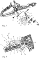
- a working device 1 which is designed as a motor chainsaw.
- the working device 1 comprises a housing 2 and a drive motor 3 arranged in the housing 2.
- the drive motor 3 is only shown schematically by a dashed rectangle.
- the drive motor 3 is an electric motor, but can alternatively be designed as a combustion engine.
- the drive motor 3 is supplied with energy via a battery or a connecting cable.
- the working device comprises a tool 4 driven by the drive motor 3, which in the embodiment is designed as a saw chain.
- a rear handle 36 and a handle tube 37 for guiding the working device 1 are attached to the housing 2.
- a guide rail 38 projects forwards.
- the saw chain is arranged all the way around the guide rail 38.
- the hand-held working device can also be, for example, a cut-off machine, a blower, a brush cutter, a hedge trimmer or the like.
- the drive motor 3 drives a drive shaft that protrudes from the housing 2.
- a drive sprocket is arranged on the drive shaft.
- the drive sprocket serves to drive the saw chain, which is guided over the drive sprocket during operation.
- the working device 1 also comprises a tensioning device, via which the guide rail 38 can be moved forwards in its longitudinal direction away from the drive sprocket and thus the saw chain can be tensioned.
- the guide rail 38 has a longitudinal axis 40.
- the longitudinal axis 40 runs centrally through the guide rail 38 approximately parallel to the horizontal floor 41.
- the term "approximately” is to be understood in such a way that the longitudinal axis 40 forms an angle of at most 15° with the floor 41.
- the guide rail 38 has a longitudinal plane 42 which, when the implement 1 is placed on a flat horizontal floor 41, contains the longitudinal axis 40 and is perpendicular to the floor 41.
- the housing 2 has a handle section 5, wherein the handle section 5 is provided on the rear handle 36 in the exemplary embodiment.
- a locking element 9 and an actuating element 8 are arranged on the handle section 5.
- the actuating element 8 serves to actuate the drive motor 3.
- the actuating element 8 is designed as an actuating lever in the exemplary embodiment.
- the locking element 9 is operatively connected to the actuating element 8.
- the locking element 9 locks the actuating element 8 in a locking position 11 ( Fig. 3 ) and releases the actuating element 8 into an operating position 10 ( Fig. 4 ) free.
- the locking element 9 is designed as a locking lever in the embodiment.
- the handle section 5 has an upper side 6 and a lower side 7 opposite the upper side 6.
- the locking element 9 is arranged on the upper side 6.
- the actuating element 8 is formed on the lower side 7 of the handle section 5.
- the handle section 5 is a part of the housing 2 on which the actuating element 8 and the locking element 9 are arranged.
- the handle section 5 also comprises a gripping area 43 which is provided for holding the working device 1 when the working device 1 is in operation.
- a housing part 44 is shown, which is designed as a support element of the working device 1.
- the drive motor 3, the guide rail 38, the actuating element 8, the locking element 9 and other components of the working device 1 are held at least indirectly.
- the housing part 44 at least partially forms a rear handle 36 ( Fig. 1 ) of the working device 1 with the handle section 5.
- the locking element 9 is mounted on the handle section 5 so as to be pivotable about a first pivot axis 13.
- the working device 1 comprises a first return spring 12, wherein the first return spring 12 acts on the locking element 9 and preloads the locking element 9 into the locking position 11.
- the first return spring 12 is designed as a leg spring in the exemplary embodiment.
- the return spring 12 is arranged on the handle section 5 and acts with one leg on the locking element 12.
- the actuating element 8 is mounted on the handle section 5 so as to be pivotable about a second pivot axis 19.
- the working device 1 has a second return spring 19, wherein the second return spring 19 acts on the actuating element 8 and preloads the actuating element 8 into an inoperative position in which the drive motor 3 is not actuated.
- a first leg 33 and a second leg 34 are formed on the locking element 9, wherein the second leg 34 is operatively connected to a holding contour 29 of the actuating element 8.
- the second leg 34 of the locking element 9 is aligned such that the second leg 34 with its front side via the holding contour 29 blocks pivoting of the actuating lever 8 into a position in which the drive motor 3 is actuated. Only by pivoting the locking element 9 does the second leg 34 release the holding contour 29 of the actuating element 8, whereby pivoting of the actuating element 8 is possible.
- the working device 1 comprises a switch 15 with a switching element 16.
- the switch 15 is held on the housing 2.
- the switch 15 can be actuated by means of the locking element 9. If the switch 15 is activated, it emits a signal.
- the implement further comprises a control circuit 17.
- the control circuit 17 is used to control the drive motor 3.
- the control circuit 17 is designed such that the drive motor 3 is only released when a group of operating conditions is met by the control circuit 17. At least one operating condition of the group of operating conditions is the receipt of the signal sent by the switch 15.
- it can also be provided to provide further operating conditions, such as the activation of an on-off switch of the implement 1, when these are met, the operation of the drive motor 3 is released by the control circuit 17.
- the locking element 9 In order to be able to activate the drive motor 3, the locking element 9 must be pressed. This firstly mechanically releases the actuating element 8 and secondly activates the switch 15, whereby the drive motor 3 is also released by the control circuit 17.
- control circuit 17 is designed as a computer-based control unit that is used for computer-aided signal processing. Consequently, the signal sent by the switch 15 can be an information signal that is further processed in the control unit. Furthermore, it can be expedient to provide only an electronic circuit as the control circuit 17. In such an embodiment, the absence of an enable signal corresponds to an interruption of the circuit by the switch, and the issuing of an enable signal corresponds to the closing of the circuit to start up the drive motor 3.
- the locking element 9 comprises a switching tongue 25 for actuating the switching element 16 of the switch 15.
- the switch 15 in the blocking position 11 of the blocking element 9, the switch 15 is actuated by the blocking element 9.
- the switching tongue 25 of the blocking element 9 contacts the switching element 16 of the switch 15.
- the switch 15 In the actuated position of the switch 15, the switch 15 is deactivated, so that the switch 15 does not send a signal to the Control circuit 17 outputs. If the locking element 9 is actuated by the operator into the operating position 10 of the locking element 9, the switching tongue 25 of the locking element 9 releases the switching element 16 of the switch 15.
- the switch 15 When the switch 15 is not actuated, the switching tongue 25 of the locking element 9 is spaced apart from the switching element 16 of the switch 15. There is no contact between the switching tongue 25 and the switching element 16.
- the switch 15 When the switch 15 is in the unactuated position, the switch 15 is activated, so that the switch 15 outputs a signal to the control circuit 17.
- the control circuit 17 enables the operation of the drive motor 3.
- the switch 15 has an actuating spring (not shown in detail) that acts on the switching element 16. In the locking position 11 of the locking element 9, the return spring 12 acts on the locking element 9 in such a way that the switching element 16 of the switch 15 is tensioned into the actuated position against the spring force of the actuating spring. The switch 15 is therefore deactivated.
- the switching element 16 is designed only as a push button, so that the locking element 9 directly contacts the push button. In an alternative embodiment of the working device 1, it may also be expedient to provide a switching tongue on the switch 16 in addition to the push button.
- the switch 15 is arranged between a part of the locking element 9 and the underside 7 of the handle section 5.
- the switch 15 and the locking element 19 are arranged in relation to one another in such a way that, in a viewing direction 45 from the top side 6 of the handle section to the underside 7 of the handle section 5, the switch 15 is at least partially, preferably completely, covered by the locking element 9.
- the switching element 16 of the switch 15 is completely covered by the locking element 9 in a viewing direction 45 from the top side 6 of the handle section to the underside 7 of the handle section 5.
- the viewing direction 45 described is perpendicular to the pivot axis 13 of the locking element 9.
- the switch 15 is arranged in the handle section 5 in such a way that the switching element 16 of the switch 15 faces the underside 7 of the handle section 5.
- a part of the locking element 9, in particular the switching tongue 25, is arranged between the switch 15 and the underside 7 of the handle section 5.
- the switching tongue 25 thus extends under the switch 15.
- the locking element 9 has a base body 20 which extends on the front side from a first end 21 to a second end 22.
- the pivot axis 13 of the locking element 9 lies between the first end 21 and the second end 22 of the base body 20.
- the front ends 21, 22 of the base body 20 are connected to one another via a first longitudinal side 23 and a second longitudinal side 24.
- the base body 20 of the locking element 9 extends along the first pivot axis 13 from its first longitudinal side 23 to its second longitudinal side 24.
- the front ends 21, 22 are connected to one another via an upper side 31 and a lower side 32.
- the lower side 32 of the base body 20 faces the lower side 7 of the handle section 5.
- the upper side 31 of the base body 20 faces away from the lower side 7 of the handle section 5.
- the base body 20 of the locking element 9 comprises the first leg 33 formed on its front, first end 21 and the second leg 34 formed on its front, second end 22.
- the switching tongue 25 of the base body 20 is arranged between the first leg 33 and the second leg 34.
- the two legs 33, 34 and the switching tongue 25 extend in their longitudinal direction in the direction from the top side 6 of the handle section 5 to the bottom side 7 of the handle section 5.
- the base body 20 of the locking element 9 comprises a first recess 27 and a second recess 28.
- the first recess 27 is formed between the first leg 33 and the switching tongue 25.
- the second recess 28 is formed between the switching tongue 25 and the second leg 34.
- the first recess 27 is designed such that in the operating position 10 of the locking element 9 the switch 15 is preferably completely in the first Recess 27 is arranged. Accordingly, in the operating position 10 of the locking element 9, the switch 15 lies laterally between the first leg 33 and the switching tongue 25 of the base body 20 of the locking element 9. In other words, the switch 15 is surrounded by the first leg 33 and the switching tongue 25.
- the second recess 28 of the base body 20 is designed such that in the operating position 10 of the locking element 9, the holding contour 29 of the actuating element 8 is arranged in the second recess 28 of the base body 20 of the locking element 9.
- the switch 15 is arranged below at least part of the locking element 9.
- the locking element 9 thus forms a type of protective device against contamination of the switch 15.
- the switch 15 is arranged in a direction from the first end 21 to the second end 22 relative to the operating position 10 of the locking element 9 between the first end 21 and the second end 22 of the base body.
- the switch 15 is arranged at least partially, in particular completely, between the first longitudinal side 23 and the second longitudinal side 24 in the direction of the first pivot axis 13.
- the switch 15 is particularly preferably aligned with the locking element 9 in such a way that the switching element 16 is arranged completely between the first longitudinal side 23 and the second longitudinal side 24 of the base body 20 of the locking element 9.
- the first end 21 of the base body 20 has a maximum end distance l 1 to the first pivot axis 13, measured radially to the pivot axis 13 of the locking element 9.
- the switch 15 is arranged between the pivot axis 13 and the first end 21 of the base body 20.
- a maximum distance between the switch 15 and the pivot axis 13, measured radially to the pivot axis 13, is less than the end distance l 1 .
- the switching element 16 of the switch 15 has a distance m 1 to the pivot axis 13 of the locking element 9, which is less than 80%, preferably less than 60% of the end distance l 1 .
- the switching element 16 of the switch 15 has a floor distance m 2 to the underside 7 of the handle section 5, wherein the distance m 2 at least 15%, preferably approximately 20% of the maximum distance d between the top side 6 and the bottom side 7 of the handle section 5 in the region of the switch.
- the switching tongue 25 comprises a cranked end section 26.
- the cranked end section 26 of the switching tongue 25 serves to actuate the switching element 16. Due to the cranking, the switching tongue 25 can actuate the switching element 16 of the switch 15, although the switching element 16 of the switch 15 is aligned towards the underside 7 of the handle section 5 and the base body 20 of the locking lever 9 is arranged substantially above the switch 15.
- the cranked end section 26 of the switching tongue 25 is arranged at least partially between the underside 7 of the handle section 5 and the switch 15.
- a distance l 2 of the cranked end section 26 to the underside 7 of the handle section 5 is less than 20% of the ground clearance m 2 between the switching element 16 and the underside 7 of the handle section 5.
- a cleaning opening 30 is formed on the underside 7 of the handle section 5. Dirt in the interior of the handle section 5 can be pushed out via the cleaning opening 30.
- the cranked end section 26 of the switching tongue 25 is arranged in the operating position 10 of the locking element 9 so adjacent to the cleaning opening 30 that dirt in the handle section 5 is conveyed out of the cleaning opening 30 via the switching tongue 25.
- the cleaning opening 30 is also arranged adjacent to the holding contour 28 of the actuating element 8 in the non-actuated state.
- the cleaning opening 30 extends in a longitudinal direction and/or in a transverse direction in each case to an extent that is at least 40%, preferably at least 60%, in particular at least 80% of the distance between the first longitudinal side 23 of the base body 20 of the locking element 9 and the second longitudinal side 24 of the base body 20 of the locking element 9.
- the transverse direction of the cleaning opening 30 corresponds approximately to the distance between the first longitudinal side 23 of the base body 20 of the locking element 9 and the second longitudinal side 24 of the base body 20 of the locking element 9. This means that dirt can be effectively pushed across the entire width of the switching tongue 25 through the cleaning opening 30.
- a lever opening 46 is provided on the upper side 6 of the handle section 5, through which the locking element 9 dips into the locking position 11 of the locking element 9 and protrudes from the handle section 5. The operator can thus actuate the locking element 9.
- the maximum distance between the locking element 9 and the handle section 5 in the area of the lever opening 46 is smaller than the transverse direction and/or the longitudinal direction of the cleaning opening 30. This ensures that dirt particles that enter the handle section 5 via the lever opening 46 can be transported out of the handle section 5 again through the cleaning opening 30.
Landscapes
- Engineering & Computer Science (AREA)
- Mechanical Engineering (AREA)
- Life Sciences & Earth Sciences (AREA)
- Wood Science & Technology (AREA)
- Forests & Forestry (AREA)
- Mechanisms For Operating Contacts (AREA)
- Tumbler Switches (AREA)
Claims (15)
- Appareil de travail manuel
comprenant- un boîtier (2),- un moteur d'entraînement (3) disposé dans le boîtier (2),- un outil (4) entraîné par le moteur d'entraînement (3),- une partie de poignée (5) formée sur le boîtier (2), la partie de poignée (5) présentant un côté supérieur (6) et un côté inférieur (7) opposé au côté supérieur (6),- un élément d'actionnement (8) pour l'actionnement du moteur d'entraînement (3),- un élément de blocage (9) disposé sur le côté supérieur (6) de la partie de poignée (5), le levier de blocage (9) étant relié fonctionnellement à l'élément d'actionnement (8), l'élément de blocage (9) bloquant l'élément d'actionnement (8) dans une position de blocage (11) et le libérant dans une position de fonctionnement (10),- un circuit de commande (17) pour la commande du moteur d'entraînement (3),- un commutateur (15) pouvant être actionné par le biais de l'élément de blocage (9) et doté d'un élément de commutation (16), le commutateur (15), dans l'état activé, envoyant un signal au circuit de commande (17),le circuit de commande (17) étant conçu de telle sorte que le moteur d'entraînement (3) n'est autorisé à fonctionner que lorsqu'un groupe de conditions de fonctionnement sont remplies par le circuit de commande (17), au moins une condition de fonctionnement du groupe de conditions de fonctionnement étant la réception du signal du commutateur (15),caractérisé en ce que le commutateur (15) est disposé dans la partie de poignée (5) entre l'élément de blocage (9) et le côté inférieur (7) de la partie de poignée (5) et est orienté de telle sorte que l'élément de commutation (16) du commutateur (15) est tourné vers le côté inférieur (7) de la partie de poignée (5). - Appareil de travail selon la revendication 1,
caractérisé en ce que l'élément de blocage (9) est monté sur le boîtier (2) de manière pivotante autour d'un premier axe de pivotement (13), l'élément de blocage (9) présentant une première extrémité (21) qui présente une distance d'extrémité maximale (l1), mesurée radialement par rapport à l'axe de pivotement (13), au premier axe de pivotement (13), et en ce qu'une distance maximale, mesurée radialement par rapport à l'axe de pivotement (13), entre le commutateur (15) et l'axe de pivotement (13) est inférieure à la distance d'extrémité (l1). - Appareil de travail selon la revendication 2,
caractérisé en ce que le commutateur (15) est disposé en direction de la première extrémité (21) par rapport au premier axe de pivotement (13) entre la première extrémité (21) et le premier axe de pivotement (13). - Appareil de travail selon la revendication 2 ou 3,
caractérisé en ce que l'élément de blocage (9) présente un corps de base (20) qui s'étend en direction du premier axe de pivotement (13) à partir d'un premier côté longitudinal (23) jusqu'à un deuxième côté longitudinal (24), l'élément de commutation (16) du commutateur (15) étant disposé en direction du premier axe de pivotement (13) entre les côtés longitudinaux (23, 24). - Appareil de travail selon l'une des revendications 1 à 4,
caractérisé en ce que l'élément de commutation (16) du commutateur (15) est réalisé sous la forme d'un bouton-poussoir. - Appareil de travail selon l'une des revendications 2 à 5,
caractérisé en ce que l'élément de commutation (16) du commutateur (15) présente une distance (m1) à l'axe de pivotement (13) de l'élément de blocage (9) qui est inférieure à 80% de la distance d'extrémité (l1). - Appareil de travail selon l'une des revendications 1 à 6,
caractérisé en ce que l'élément de blocage (9) présente une languette de commutation (25) pour l'actionnement de l'élément de commutation (16) du commutateur (15). - Appareil de travail selon la revendication 7,
caractérisé en ce que la languette de commutation (25) présente une partie d'extrémité coudée (26), la partie d'extrémité coudée (26) servant à l'actionnement du commutateur (15). - Appareil de travail selon la revendication 7 ou 8,
caractérisé en ce que la languette de commutation (25) est disposée, dans la position bloquée, entre le côté inférieur (7) de la partie de poignée (5) et le commutateur (15). - Appareil de travail selon l'une des revendications 1 à 9,
caractérisé en ce qu'une ouverture de nettoyage (30) est formée sur le côté inférieur (7) de la partie de poignée (5). - Appareil de travail selon la revendication 10,
caractérisé en ce que, dans la position de fonctionnement (10) de l'élément de blocage (9), la partie d'extrémité coudée (26) de la languette commutation (25) est disposée de manière adjacente à l'ouverture de nettoyage (30) de telle sorte que des salissures dans la partie de poignée (5) sont transportées hors de l'ouverture de nettoyage (30) par le biais de la languette de commutation (25). - Appareil de travail selon l'une des revendications 4 à 11,
caractérisé en ce que le corps de base (20) de l'élément de blocage (9) présente un premier évidement (27), le commutateur (15) étant disposé dans le premier évidement (27) dans la position de fonctionnement (10) de l'élément de blocage (9). - Appareil de travail selon l'une des revendications 1 à 12,
caractérisé en ce que l'élément de commutation (16) du commutateur (15) est actionné par l'élément de blocage (9) dans la position de blocage (11) de l'élément de blocage (9), de sorte que le commutateur (15) soit désactivé. - Appareil de travail selon l'une des revendications 1 à 13,
caractérisé en ce que l'élément de commutation (16) du commutateur (15) n'est pas actionné dans la position de fonctionnement (10) de l'élément de blocage (9), de sorte que le commutateur (15) soit activé. - Appareil de travail selon l'une des revendications 1 à 14,
caractérisé en ce que le commutateur (15) présente un ressort d'actionnement agissant sur l'élément de commutation (16), et en ce que l'élément de blocage (9), dans l'état non actionné, est retenu dans la position de blocage (11) par le biais d'un premier ressort de rappel (12), le premier ressort de rappel (12) agissant sur le ressort d'actionnement du commutateur (15) dans la position de blocage (11) de l'élément de blocage (9), de sorte que le commutateur (15) soit désactivé.
Applications Claiming Priority (1)
| Application Number | Priority Date | Filing Date | Title |
|---|---|---|---|
| EP22154055 | 2022-01-28 |
Publications (2)
| Publication Number | Publication Date |
|---|---|
| EP4219081A1 EP4219081A1 (fr) | 2023-08-02 |
| EP4219081B1 true EP4219081B1 (fr) | 2024-11-06 |
Family
ID=80123044
Family Applications (1)
| Application Number | Title | Priority Date | Filing Date |
|---|---|---|---|
| EP23153563.4A Active EP4219081B1 (fr) | 2022-01-28 | 2023-01-26 | Outil manuel |
Country Status (3)
| Country | Link |
|---|---|
| US (1) | US12515290B2 (fr) |
| EP (1) | EP4219081B1 (fr) |
| CN (1) | CN116511600A (fr) |
Family Cites Families (29)
| Publication number | Priority date | Publication date | Assignee | Title |
|---|---|---|---|---|
| US3774303A (en) * | 1966-02-25 | 1973-11-27 | Chain saw starting system | |
| US3873796A (en) * | 1973-07-06 | 1975-03-25 | Black & Decker Mfg Co | Trigger mechanism for hand-operated power device including independently operable locking devices providing automatic lock off and manual lock-on operation |
| DE3033604A1 (de) * | 1980-09-06 | 1982-04-22 | Fa. Andreas Stihl, 7050 Waiblingen | Motorsaege |
| SE458513B (sv) * | 1987-08-11 | 1989-04-10 | Electrolux Ab | Anordning av gasreglage paa motorsaag |
| US4879438A (en) * | 1988-08-01 | 1989-11-07 | Ryobi Motor Products Corp. | Lock-on/lock-off switch for power tool |
| DE9018178U1 (de) * | 1989-09-08 | 1998-04-09 | Fa. Andreas Stihl, 71336 Waiblingen | Handgeführtes Arbeitsgerät |
| JP2538321Y2 (ja) * | 1991-01-23 | 1997-06-11 | 株式会社共立 | チェーンソー |
| GB9224660D0 (en) * | 1992-11-25 | 1993-01-13 | Black & Decker Inc | Improved switch mechanism |
| US5483727A (en) * | 1995-03-02 | 1996-01-16 | P&F Brother Industrial Corporation | Operating handle for a cutting device |
| US5577600A (en) * | 1995-11-21 | 1996-11-26 | Emerson Electric Co. | Switch lock-out device for power tool |
| DE19621729B4 (de) * | 1996-05-29 | 2007-10-25 | Starting Industrial Co., Ltd. | Gashebeleinrichtung für einen Motor |
| US5638945A (en) * | 1996-06-10 | 1997-06-17 | Ryobi North America, Inc. | Locking trigger mechanism for a portable power tool |
| US6108916A (en) * | 1998-08-14 | 2000-08-29 | Milwaukee Electric Tool Corporation | Movable handle for a power tool |
| US6575285B2 (en) * | 2001-11-14 | 2003-06-10 | Jenn Feng Industrial Co., Ltd. | Safety switch for power tools |
| US6548776B1 (en) * | 2002-04-12 | 2003-04-15 | Jenn Feng Industrial Co., Ltd. | Safety device for on/off switch of an electric tool |
| DE10332241A1 (de) * | 2003-07-16 | 2005-02-03 | Andreas Stihl Ag & Co. Kg | Handgeführtes Arbeitsgerät |
| DE102005038629B3 (de) * | 2005-08-10 | 2006-12-21 | Siemens Ag | Formschlüssige Verriegelung zur Verhinderung des Einschaltens eines Schalters |
| DE102006000316A1 (de) * | 2006-06-29 | 2008-01-03 | Hilti Ag | Haupthandgriff mit Sicherungsverriegelung |
| US8752301B2 (en) * | 2009-04-08 | 2014-06-17 | Rex George | Chainsaw incorporating a safety device system |
| WO2010115438A1 (fr) * | 2009-04-08 | 2010-10-14 | Husqvarna Ab | Outils portables alimentés par pile |
| DE102012025309A1 (de) * | 2012-12-22 | 2014-06-26 | Andreas Stihl Ag & Co. Kg | Handgeführtes Arbeitsgerät mit einem Antriebsmotor zum Antrieb mindestens eines Werkzeugs und Verfahren zu dessen Betrieb |
| DE102013009891A1 (de) * | 2013-06-13 | 2014-12-18 | Andreas Stihl Ag & Co. Kg | Arbeitsgerät mit einem Verbrennungsmotor |
| US10014128B2 (en) * | 2013-12-17 | 2018-07-03 | Robert Bosch Tool Corporation | Portable power tool with trigger switch, trigger release and lock-on mechanism combination |
| DE102014009144A1 (de) * | 2014-06-20 | 2015-12-24 | Andreas Stihl Ag & Co. Kg | Handgeführtes Arbeitsgerät |
| JP6556536B2 (ja) * | 2015-07-13 | 2019-08-07 | 株式会社マキタ | チェーンソー |
| DE102015012043A1 (de) * | 2015-09-15 | 2017-03-16 | Andreas Stihl Ag & Co. Kg | Verfahren zur Inbetriebnahme eines handgeführten Arbeitsgerätes mit einem Elektromotor |
| DE102017002353A1 (de) | 2017-03-11 | 2018-09-13 | Andreas Stihl Ag & Co. Kg | Handgeführtes Arbeitsgerät |
| US12064894B2 (en) * | 2020-09-04 | 2024-08-20 | Milwaukee Electric Tool Corporation | Chainsaw |
| EP4342638A4 (fr) * | 2021-05-21 | 2025-02-12 | Globe (Jiangsu) Co., Ltd. | Outil électrique portatif |
-
2023
- 2023-01-13 CN CN202310071978.6A patent/CN116511600A/zh active Pending
- 2023-01-26 US US18/159,752 patent/US12515290B2/en active Active
- 2023-01-26 EP EP23153563.4A patent/EP4219081B1/fr active Active
Also Published As
| Publication number | Publication date |
|---|---|
| US20230241755A1 (en) | 2023-08-03 |
| CN116511600A (zh) | 2023-08-01 |
| EP4219081A1 (fr) | 2023-08-02 |
| US12515290B2 (en) | 2026-01-06 |
Similar Documents
| Publication | Publication Date | Title |
|---|---|---|
| EP2746008B1 (fr) | Outillage portatif doté d'un moteur d'entraînement d'au moins un outil et son procédé de fonctionnement | |
| DE202010008031U1 (de) | Verriegelungs-Schaltervorrichtung für ein Kraftwerkzeug | |
| EP2957391A1 (fr) | Appareil de travail portatif | |
| DE102021005988A1 (de) | Heckenschere | |
| EP2425927A2 (fr) | Meuleuse | |
| EP2036103B1 (fr) | Commutateur électrique à élément de blocage | |
| DE69105068T2 (de) | Kraftwerkzeug. | |
| WO2005046940A1 (fr) | Outil electrique a main | |
| EP3372348A1 (fr) | Appareil de travail portatif | |
| EP1092379A1 (fr) | Mixeur à main électrique | |
| CH671725A5 (fr) | ||
| EP4219081B1 (fr) | Outil manuel | |
| EP0047416A1 (fr) | Dispositif d'interrupteur de sécurité pour une tondeuse à gazon électrique | |
| EP0054912B1 (fr) | Dispositif, en particulier dispositif portatif, pour l'usinage de pièces en forme de tubes et/ou de barres et analogues | |
| EP4494824A1 (fr) | Outil portatif | |
| DE3324545A1 (de) | Elektromotorisch betriebenes handgeraet | |
| DE3247299C2 (de) | Elektrische Schneidevorrichtung für Lebensmittel, insbesondere Elektromesser | |
| EP4364912A1 (fr) | Machine d'usinage électrique | |
| DE202008002672U1 (de) | Elektrisches Handwerkzeug | |
| EP0146489A1 (fr) | Coupeuse ménagère, en particulier coupeuse entraînée par moteur électrique | |
| DE69630097T2 (de) | Ein Schalter mit Ein- und Ausverriegelung | |
| EP4292767B1 (fr) | Outil de travail guidé à la main | |
| DE69201435T2 (de) | Sicherheitshebeleinheit für ein Kraftwerkzeug. | |
| DE10361297B3 (de) | Kreissäge | |
| DE3033346A1 (de) | Sicherheitsschaltvorrichtung fuer elektrorasenmaeher |
Legal Events
| Date | Code | Title | Description |
|---|---|---|---|
| PUAI | Public reference made under article 153(3) epc to a published international application that has entered the european phase |
Free format text: ORIGINAL CODE: 0009012 |
|
| STAA | Information on the status of an ep patent application or granted ep patent |
Free format text: STATUS: THE APPLICATION HAS BEEN PUBLISHED |
|
| AK | Designated contracting states |
Kind code of ref document: A1 Designated state(s): AL AT BE BG CH CY CZ DE DK EE ES FI FR GB GR HR HU IE IS IT LI LT LU LV MC ME MK MT NL NO PL PT RO RS SE SI SK SM TR |
|
| STAA | Information on the status of an ep patent application or granted ep patent |
Free format text: STATUS: REQUEST FOR EXAMINATION WAS MADE |
|
| 17P | Request for examination filed |
Effective date: 20240125 |
|
| RBV | Designated contracting states (corrected) |
Designated state(s): AL AT BE BG CH CY CZ DE DK EE ES FI FR GB GR HR HU IE IS IT LI LT LU LV MC ME MK MT NL NO PL PT RO RS SE SI SK SM TR |
|
| GRAP | Despatch of communication of intention to grant a patent |
Free format text: ORIGINAL CODE: EPIDOSNIGR1 |
|
| STAA | Information on the status of an ep patent application or granted ep patent |
Free format text: STATUS: GRANT OF PATENT IS INTENDED |
|
| RIC1 | Information provided on ipc code assigned before grant |
Ipc: B25F 5/02 20060101ALI20240514BHEP Ipc: B25F 5/00 20060101AFI20240514BHEP |
|
| INTG | Intention to grant announced |
Effective date: 20240529 |
|
| GRAS | Grant fee paid |
Free format text: ORIGINAL CODE: EPIDOSNIGR3 |
|
| GRAA | (expected) grant |
Free format text: ORIGINAL CODE: 0009210 |
|
| STAA | Information on the status of an ep patent application or granted ep patent |
Free format text: STATUS: THE PATENT HAS BEEN GRANTED |
|
| AK | Designated contracting states |
Kind code of ref document: B1 Designated state(s): AL AT BE BG CH CY CZ DE DK EE ES FI FR GB GR HR HU IE IS IT LI LT LU LV MC ME MK MT NL NO PL PT RO RS SE SI SK SM TR |
|
| REG | Reference to a national code |
Ref country code: GB Ref legal event code: FG4D Free format text: NOT ENGLISH |
|
| REG | Reference to a national code |
Ref country code: CH Ref legal event code: EP |
|
| REG | Reference to a national code |
Ref country code: DE Ref legal event code: R096 Ref document number: 502023000258 Country of ref document: DE |
|
| REG | Reference to a national code |
Ref country code: IE Ref legal event code: FG4D Free format text: LANGUAGE OF EP DOCUMENT: GERMAN |
|
| REG | Reference to a national code |
Ref country code: LT Ref legal event code: MG9D |
|
| REG | Reference to a national code |
Ref country code: NL Ref legal event code: MP Effective date: 20241106 |
|
| PG25 | Lapsed in a contracting state [announced via postgrant information from national office to epo] |
Ref country code: HR Free format text: LAPSE BECAUSE OF FAILURE TO SUBMIT A TRANSLATION OF THE DESCRIPTION OR TO PAY THE FEE WITHIN THE PRESCRIBED TIME-LIMIT Effective date: 20241106 Ref country code: PT Free format text: LAPSE BECAUSE OF FAILURE TO SUBMIT A TRANSLATION OF THE DESCRIPTION OR TO PAY THE FEE WITHIN THE PRESCRIBED TIME-LIMIT Effective date: 20250306 Ref country code: IS Free format text: LAPSE BECAUSE OF FAILURE TO SUBMIT A TRANSLATION OF THE DESCRIPTION OR TO PAY THE FEE WITHIN THE PRESCRIBED TIME-LIMIT Effective date: 20250306 |
|
| PG25 | Lapsed in a contracting state [announced via postgrant information from national office to epo] |
Ref country code: FI Free format text: LAPSE BECAUSE OF FAILURE TO SUBMIT A TRANSLATION OF THE DESCRIPTION OR TO PAY THE FEE WITHIN THE PRESCRIBED TIME-LIMIT Effective date: 20241106 Ref country code: NL Free format text: LAPSE BECAUSE OF FAILURE TO SUBMIT A TRANSLATION OF THE DESCRIPTION OR TO PAY THE FEE WITHIN THE PRESCRIBED TIME-LIMIT Effective date: 20241106 |
|
| PG25 | Lapsed in a contracting state [announced via postgrant information from national office to epo] |
Ref country code: BG Free format text: LAPSE BECAUSE OF FAILURE TO SUBMIT A TRANSLATION OF THE DESCRIPTION OR TO PAY THE FEE WITHIN THE PRESCRIBED TIME-LIMIT Effective date: 20241106 |
|
| PG25 | Lapsed in a contracting state [announced via postgrant information from national office to epo] |
Ref country code: ES Free format text: LAPSE BECAUSE OF FAILURE TO SUBMIT A TRANSLATION OF THE DESCRIPTION OR TO PAY THE FEE WITHIN THE PRESCRIBED TIME-LIMIT Effective date: 20241106 |
|
| PG25 | Lapsed in a contracting state [announced via postgrant information from national office to epo] |
Ref country code: NO Free format text: LAPSE BECAUSE OF FAILURE TO SUBMIT A TRANSLATION OF THE DESCRIPTION OR TO PAY THE FEE WITHIN THE PRESCRIBED TIME-LIMIT Effective date: 20250206 |
|
| PG25 | Lapsed in a contracting state [announced via postgrant information from national office to epo] |
Ref country code: LV Free format text: LAPSE BECAUSE OF FAILURE TO SUBMIT A TRANSLATION OF THE DESCRIPTION OR TO PAY THE FEE WITHIN THE PRESCRIBED TIME-LIMIT Effective date: 20241106 Ref country code: GR Free format text: LAPSE BECAUSE OF FAILURE TO SUBMIT A TRANSLATION OF THE DESCRIPTION OR TO PAY THE FEE WITHIN THE PRESCRIBED TIME-LIMIT Effective date: 20250207 |
|
| PG25 | Lapsed in a contracting state [announced via postgrant information from national office to epo] |
Ref country code: PL Free format text: LAPSE BECAUSE OF FAILURE TO SUBMIT A TRANSLATION OF THE DESCRIPTION OR TO PAY THE FEE WITHIN THE PRESCRIBED TIME-LIMIT Effective date: 20241106 |
|
| PG25 | Lapsed in a contracting state [announced via postgrant information from national office to epo] |
Ref country code: RS Free format text: LAPSE BECAUSE OF FAILURE TO SUBMIT A TRANSLATION OF THE DESCRIPTION OR TO PAY THE FEE WITHIN THE PRESCRIBED TIME-LIMIT Effective date: 20250206 |
|
| PG25 | Lapsed in a contracting state [announced via postgrant information from national office to epo] |
Ref country code: SM Free format text: LAPSE BECAUSE OF FAILURE TO SUBMIT A TRANSLATION OF THE DESCRIPTION OR TO PAY THE FEE WITHIN THE PRESCRIBED TIME-LIMIT Effective date: 20241106 |
|
| PG25 | Lapsed in a contracting state [announced via postgrant information from national office to epo] |
Ref country code: DK Free format text: LAPSE BECAUSE OF FAILURE TO SUBMIT A TRANSLATION OF THE DESCRIPTION OR TO PAY THE FEE WITHIN THE PRESCRIBED TIME-LIMIT Effective date: 20241106 |
|
| PG25 | Lapsed in a contracting state [announced via postgrant information from national office to epo] |
Ref country code: EE Free format text: LAPSE BECAUSE OF FAILURE TO SUBMIT A TRANSLATION OF THE DESCRIPTION OR TO PAY THE FEE WITHIN THE PRESCRIBED TIME-LIMIT Effective date: 20241106 |
|
| PG25 | Lapsed in a contracting state [announced via postgrant information from national office to epo] |
Ref country code: RO Free format text: LAPSE BECAUSE OF FAILURE TO SUBMIT A TRANSLATION OF THE DESCRIPTION OR TO PAY THE FEE WITHIN THE PRESCRIBED TIME-LIMIT Effective date: 20241106 |
|
| PG25 | Lapsed in a contracting state [announced via postgrant information from national office to epo] |
Ref country code: SK Free format text: LAPSE BECAUSE OF FAILURE TO SUBMIT A TRANSLATION OF THE DESCRIPTION OR TO PAY THE FEE WITHIN THE PRESCRIBED TIME-LIMIT Effective date: 20241106 |
|
| PG25 | Lapsed in a contracting state [announced via postgrant information from national office to epo] |
Ref country code: CZ Free format text: LAPSE BECAUSE OF FAILURE TO SUBMIT A TRANSLATION OF THE DESCRIPTION OR TO PAY THE FEE WITHIN THE PRESCRIBED TIME-LIMIT Effective date: 20241106 |
|
| PG25 | Lapsed in a contracting state [announced via postgrant information from national office to epo] |
Ref country code: IT Free format text: LAPSE BECAUSE OF FAILURE TO SUBMIT A TRANSLATION OF THE DESCRIPTION OR TO PAY THE FEE WITHIN THE PRESCRIBED TIME-LIMIT Effective date: 20241106 |
|
| REG | Reference to a national code |
Ref country code: DE Ref legal event code: R097 Ref document number: 502023000258 Country of ref document: DE |
|
| PG25 | Lapsed in a contracting state [announced via postgrant information from national office to epo] |
Ref country code: SE Free format text: LAPSE BECAUSE OF FAILURE TO SUBMIT A TRANSLATION OF THE DESCRIPTION OR TO PAY THE FEE WITHIN THE PRESCRIBED TIME-LIMIT Effective date: 20241106 |
|
| PLBE | No opposition filed within time limit |
Free format text: ORIGINAL CODE: 0009261 |
|
| STAA | Information on the status of an ep patent application or granted ep patent |
Free format text: STATUS: NO OPPOSITION FILED WITHIN TIME LIMIT |
|
| PG25 | Lapsed in a contracting state [announced via postgrant information from national office to epo] |
Ref country code: LU Free format text: LAPSE BECAUSE OF NON-PAYMENT OF DUE FEES Effective date: 20250126 Ref country code: MC Free format text: LAPSE BECAUSE OF FAILURE TO SUBMIT A TRANSLATION OF THE DESCRIPTION OR TO PAY THE FEE WITHIN THE PRESCRIBED TIME-LIMIT Effective date: 20241106 |
|
| 26N | No opposition filed |
Effective date: 20250807 |
|
| PG25 | Lapsed in a contracting state [announced via postgrant information from national office to epo] |
Ref country code: BE Free format text: LAPSE BECAUSE OF NON-PAYMENT OF DUE FEES Effective date: 20250131 |
|
| REG | Reference to a national code |
Ref country code: BE Ref legal event code: MM Effective date: 20250131 |
|
| PG25 | Lapsed in a contracting state [announced via postgrant information from national office to epo] |
Ref country code: IE Free format text: LAPSE BECAUSE OF NON-PAYMENT OF DUE FEES Effective date: 20250126 |
|
| PGFP | Annual fee paid to national office [announced via postgrant information from national office to epo] |
Ref country code: DE Payment date: 20260127 Year of fee payment: 4 |
|
| PGFP | Annual fee paid to national office [announced via postgrant information from national office to epo] |
Ref country code: AT Payment date: 20260301 Year of fee payment: 4 |
|
| PGFP | Annual fee paid to national office [announced via postgrant information from national office to epo] |
Ref country code: FR Payment date: 20260126 Year of fee payment: 4 |