EP4494830A1 - Structure de superposition de fibres en forme de bréchet pour profil aérodynamique - Google Patents
Structure de superposition de fibres en forme de bréchet pour profil aérodynamique Download PDFInfo
- Publication number
- EP4494830A1 EP4494830A1 EP24188460.0A EP24188460A EP4494830A1 EP 4494830 A1 EP4494830 A1 EP 4494830A1 EP 24188460 A EP24188460 A EP 24188460A EP 4494830 A1 EP4494830 A1 EP 4494830A1
- Authority
- EP
- European Patent Office
- Prior art keywords
- tows
- section
- single leg
- fiber
- airfoil
- Prior art date
- Legal status (The legal status is an assumption and is not a legal conclusion. Google has not performed a legal analysis and makes no representation as to the accuracy of the status listed.)
- Pending
Links
Images


Classifications
-
- F—MECHANICAL ENGINEERING; LIGHTING; HEATING; WEAPONS; BLASTING
- F01—MACHINES OR ENGINES IN GENERAL; ENGINE PLANTS IN GENERAL; STEAM ENGINES
- F01D—NON-POSITIVE DISPLACEMENT MACHINES OR ENGINES, e.g. STEAM TURBINES
- F01D5/00—Blades; Blade-carrying members; Heating, heat-insulating, cooling or antivibration means on the blades or the members
- F01D5/12—Blades
- F01D5/28—Selecting particular materials; Particular measures relating thereto; Measures against erosion or corrosion
-
- C—CHEMISTRY; METALLURGY
- C04—CEMENTS; CONCRETE; ARTIFICIAL STONE; CERAMICS; REFRACTORIES
- C04B—LIME, MAGNESIA; SLAG; CEMENTS; COMPOSITIONS THEREOF, e.g. MORTARS, CONCRETE OR LIKE BUILDING MATERIALS; ARTIFICIAL STONE; CERAMICS; REFRACTORIES; TREATMENT OF NATURAL STONE
- C04B35/00—Shaped ceramic products characterised by their composition; Ceramics compositions; Processing powders of inorganic compounds preparatory to the manufacturing of ceramic products
- C04B35/71—Ceramic products containing macroscopic reinforcing agents
- C04B35/78—Ceramic products containing macroscopic reinforcing agents containing non-metallic materials
- C04B35/80—Fibres, filaments, whiskers, platelets, or the like
-
- D—TEXTILES; PAPER
- D03—WEAVING
- D03D—WOVEN FABRICS; METHODS OF WEAVING; LOOMS
- D03D1/00—Woven fabrics designed to make specified articles
-
- D—TEXTILES; PAPER
- D03—WEAVING
- D03D—WOVEN FABRICS; METHODS OF WEAVING; LOOMS
- D03D25/00—Woven fabrics not otherwise provided for
- D03D25/005—Three-dimensional woven fabrics
-
- D—TEXTILES; PAPER
- D03—WEAVING
- D03D—WOVEN FABRICS; METHODS OF WEAVING; LOOMS
- D03D3/00—Woven fabrics characterised by their shape
-
- F—MECHANICAL ENGINEERING; LIGHTING; HEATING; WEAPONS; BLASTING
- F01—MACHINES OR ENGINES IN GENERAL; ENGINE PLANTS IN GENERAL; STEAM ENGINES
- F01D—NON-POSITIVE DISPLACEMENT MACHINES OR ENGINES, e.g. STEAM TURBINES
- F01D5/00—Blades; Blade-carrying members; Heating, heat-insulating, cooling or antivibration means on the blades or the members
- F01D5/12—Blades
- F01D5/14—Form or construction
- F01D5/147—Construction, i.e. structural features, e.g. of weight-saving hollow blades
-
- F—MECHANICAL ENGINEERING; LIGHTING; HEATING; WEAPONS; BLASTING
- F01—MACHINES OR ENGINES IN GENERAL; ENGINE PLANTS IN GENERAL; STEAM ENGINES
- F01D—NON-POSITIVE DISPLACEMENT MACHINES OR ENGINES, e.g. STEAM TURBINES
- F01D5/00—Blades; Blade-carrying members; Heating, heat-insulating, cooling or antivibration means on the blades or the members
- F01D5/12—Blades
- F01D5/28—Selecting particular materials; Particular measures relating thereto; Measures against erosion or corrosion
- F01D5/282—Selecting composite materials, e.g. blades with reinforcing filaments
-
- F—MECHANICAL ENGINEERING; LIGHTING; HEATING; WEAPONS; BLASTING
- F01—MACHINES OR ENGINES IN GENERAL; ENGINE PLANTS IN GENERAL; STEAM ENGINES
- F01D—NON-POSITIVE DISPLACEMENT MACHINES OR ENGINES, e.g. STEAM TURBINES
- F01D9/00—Stators
- F01D9/06—Fluid supply conduits to nozzles or the like
- F01D9/065—Fluid supply or removal conduits traversing the working fluid flow, e.g. for lubrication-, cooling-, or sealing fluids
-
- C—CHEMISTRY; METALLURGY
- C04—CEMENTS; CONCRETE; ARTIFICIAL STONE; CERAMICS; REFRACTORIES
- C04B—LIME, MAGNESIA; SLAG; CEMENTS; COMPOSITIONS THEREOF, e.g. MORTARS, CONCRETE OR LIKE BUILDING MATERIALS; ARTIFICIAL STONE; CERAMICS; REFRACTORIES; TREATMENT OF NATURAL STONE
- C04B2235/00—Aspects relating to ceramic starting mixtures or sintered ceramic products
- C04B2235/02—Composition of constituents of the starting material or of secondary phases of the final product
- C04B2235/30—Constituents and secondary phases not being of a fibrous nature
- C04B2235/38—Non-oxide ceramic constituents or additives
- C04B2235/3817—Carbides
- C04B2235/3826—Silicon carbides
-
- C—CHEMISTRY; METALLURGY
- C04—CEMENTS; CONCRETE; ARTIFICIAL STONE; CERAMICS; REFRACTORIES
- C04B—LIME, MAGNESIA; SLAG; CEMENTS; COMPOSITIONS THEREOF, e.g. MORTARS, CONCRETE OR LIKE BUILDING MATERIALS; ARTIFICIAL STONE; CERAMICS; REFRACTORIES; TREATMENT OF NATURAL STONE
- C04B2235/00—Aspects relating to ceramic starting mixtures or sintered ceramic products
- C04B2235/02—Composition of constituents of the starting material or of secondary phases of the final product
- C04B2235/30—Constituents and secondary phases not being of a fibrous nature
- C04B2235/38—Non-oxide ceramic constituents or additives
- C04B2235/3852—Nitrides, e.g. oxynitrides, carbonitrides, oxycarbonitrides, lithium nitride, magnesium nitride
- C04B2235/3873—Silicon nitrides, e.g. silicon carbonitride, silicon oxynitride
-
- C—CHEMISTRY; METALLURGY
- C04—CEMENTS; CONCRETE; ARTIFICIAL STONE; CERAMICS; REFRACTORIES
- C04B—LIME, MAGNESIA; SLAG; CEMENTS; COMPOSITIONS THEREOF, e.g. MORTARS, CONCRETE OR LIKE BUILDING MATERIALS; ARTIFICIAL STONE; CERAMICS; REFRACTORIES; TREATMENT OF NATURAL STONE
- C04B2235/00—Aspects relating to ceramic starting mixtures or sintered ceramic products
- C04B2235/02—Composition of constituents of the starting material or of secondary phases of the final product
- C04B2235/50—Constituents or additives of the starting mixture chosen for their shape or used because of their shape or their physical appearance
- C04B2235/52—Constituents or additives characterised by their shapes
- C04B2235/5208—Fibers
- C04B2235/5216—Inorganic
- C04B2235/524—Non-oxidic, e.g. borides, carbides, silicides or nitrides
- C04B2235/5244—Silicon carbide
-
- C—CHEMISTRY; METALLURGY
- C04—CEMENTS; CONCRETE; ARTIFICIAL STONE; CERAMICS; REFRACTORIES
- C04B—LIME, MAGNESIA; SLAG; CEMENTS; COMPOSITIONS THEREOF, e.g. MORTARS, CONCRETE OR LIKE BUILDING MATERIALS; ARTIFICIAL STONE; CERAMICS; REFRACTORIES; TREATMENT OF NATURAL STONE
- C04B2235/00—Aspects relating to ceramic starting mixtures or sintered ceramic products
- C04B2235/02—Composition of constituents of the starting material or of secondary phases of the final product
- C04B2235/50—Constituents or additives of the starting mixture chosen for their shape or used because of their shape or their physical appearance
- C04B2235/52—Constituents or additives characterised by their shapes
- C04B2235/5208—Fibers
- C04B2235/5252—Fibers having a specific pre-form
- C04B2235/5256—Two-dimensional, e.g. woven structures
-
- D—TEXTILES; PAPER
- D10—INDEXING SCHEME ASSOCIATED WITH SUBLASSES OF SECTION D, RELATING TO TEXTILES
- D10B—INDEXING SCHEME ASSOCIATED WITH SUBLASSES OF SECTION D, RELATING TO TEXTILES
- D10B2403/00—Details of fabric structure established in the fabric forming process
- D10B2403/03—Shape features
- D10B2403/033—Three dimensional fabric, e.g. forming or comprising cavities in or protrusions from the basic planar configuration, or deviations from the cylindrical shape as generally imposed by the fabric forming process
- D10B2403/0332—Three dimensional fabric, e.g. forming or comprising cavities in or protrusions from the basic planar configuration, or deviations from the cylindrical shape as generally imposed by the fabric forming process with gussets folding into three dimensional shape, e.g. seat covers
-
- D—TEXTILES; PAPER
- D10—INDEXING SCHEME ASSOCIATED WITH SUBLASSES OF SECTION D, RELATING TO TEXTILES
- D10B—INDEXING SCHEME ASSOCIATED WITH SUBLASSES OF SECTION D, RELATING TO TEXTILES
- D10B2505/00—Industrial
- D10B2505/02—Reinforcing materials; Prepregs
-
- F—MECHANICAL ENGINEERING; LIGHTING; HEATING; WEAPONS; BLASTING
- F05—INDEXING SCHEMES RELATING TO ENGINES OR PUMPS IN VARIOUS SUBCLASSES OF CLASSES F01-F04
- F05D—INDEXING SCHEME FOR ASPECTS RELATING TO NON-POSITIVE-DISPLACEMENT MACHINES OR ENGINES, GAS-TURBINES OR JET-PROPULSION PLANTS
- F05D2240/00—Components
- F05D2240/10—Stators
- F05D2240/12—Fluid guiding means, e.g. vanes
- F05D2240/122—Fluid guiding means, e.g. vanes related to the trailing edge of a stator vane
-
- F—MECHANICAL ENGINEERING; LIGHTING; HEATING; WEAPONS; BLASTING
- F05—INDEXING SCHEMES RELATING TO ENGINES OR PUMPS IN VARIOUS SUBCLASSES OF CLASSES F01-F04
- F05D—INDEXING SCHEME FOR ASPECTS RELATING TO NON-POSITIVE-DISPLACEMENT MACHINES OR ENGINES, GAS-TURBINES OR JET-PROPULSION PLANTS
- F05D2240/00—Components
- F05D2240/20—Rotors
- F05D2240/30—Characteristics of rotor blades, i.e. of any element transforming dynamic fluid energy to or from rotational energy and being attached to a rotor
- F05D2240/304—Characteristics of rotor blades, i.e. of any element transforming dynamic fluid energy to or from rotational energy and being attached to a rotor related to the trailing edge of a rotor blade
-
- F—MECHANICAL ENGINEERING; LIGHTING; HEATING; WEAPONS; BLASTING
- F05—INDEXING SCHEMES RELATING TO ENGINES OR PUMPS IN VARIOUS SUBCLASSES OF CLASSES F01-F04
- F05D—INDEXING SCHEME FOR ASPECTS RELATING TO NON-POSITIVE-DISPLACEMENT MACHINES OR ENGINES, GAS-TURBINES OR JET-PROPULSION PLANTS
- F05D2300/00—Materials; Properties thereof
- F05D2300/60—Properties or characteristics given to material by treatment or manufacturing
- F05D2300/601—Fabrics
- F05D2300/6012—Woven fabrics
-
- F—MECHANICAL ENGINEERING; LIGHTING; HEATING; WEAPONS; BLASTING
- F05—INDEXING SCHEMES RELATING TO ENGINES OR PUMPS IN VARIOUS SUBCLASSES OF CLASSES F01-F04
- F05D—INDEXING SCHEME FOR ASPECTS RELATING TO NON-POSITIVE-DISPLACEMENT MACHINES OR ENGINES, GAS-TURBINES OR JET-PROPULSION PLANTS
- F05D2300/00—Materials; Properties thereof
- F05D2300/60—Properties or characteristics given to material by treatment or manufacturing
- F05D2300/603—Composites; e.g. fibre-reinforced
- F05D2300/6033—Ceramic matrix composites [CMC]
-
- F—MECHANICAL ENGINEERING; LIGHTING; HEATING; WEAPONS; BLASTING
- F05—INDEXING SCHEMES RELATING TO ENGINES OR PUMPS IN VARIOUS SUBCLASSES OF CLASSES F01-F04
- F05D—INDEXING SCHEME FOR ASPECTS RELATING TO NON-POSITIVE-DISPLACEMENT MACHINES OR ENGINES, GAS-TURBINES OR JET-PROPULSION PLANTS
- F05D2300/00—Materials; Properties thereof
- F05D2300/60—Properties or characteristics given to material by treatment or manufacturing
- F05D2300/603—Composites; e.g. fibre-reinforced
- F05D2300/6034—Orientation of fibres, weaving, ply angle
Definitions
- a gas turbine engine typically includes a fan section, a compressor section, a combustor section and a turbine section. Air entering the compressor section is compressed and delivered into the combustion section where it is mixed with fuel and ignited to generate a high-pressure and temperature exhaust gas flow. The high-pressure and temperature exhaust gas flow expands through the turbine section to drive the compressor and the fan section.
- the compressor section may include low and high pressure compressors, and the turbine section may also include low and high pressure turbines.
- Airfoils in the turbine section are typically formed of a superalloy and may include thermal barrier coatings to extend temperature capability and lifetime. Ceramic matrix composite (“CMC”) materials are also being considered for airfoils. Among other attractive properties, CMCs have high temperature resistance. Despite this attribute, however, there are unique challenges to implementing CMCs in airfoils.
- An airfoil includes an airfoil wall that circumscribes a cavity and defines a leading edge, a trailing edge, and pressure and suction sides that join the leading edge and the trailing edge.
- the airfoil wall includes a wishbone-shaped fiber layup structure.
- the wishbone-shaped fiber layup structure has first and second arms that merge into a single leg.
- the first and second arms are comprised of a network of fiber tows.
- the single leg has fiber tows from each of the first and second arms that are interwoven.
- the single leg forms at least a portion of the trailing edge of the airfoil wall.
- Each of the first and second arms include a first section that is distal from the single leg and a second section that is proximal to the single leg.
- the first section defines a first thickness and a first fiber tow count.
- the second section defines a second thickness that is greater than the first thickness and a second fiber tow count that is greater than the first fiber tow count.
- the single leg defines a third thickness that is greater than the second thickness and a third fiber tow count that is greater than the second fiber tow count.
- the first section, the second section, and the single leg each have a weave pattern, and the weave pattern of one of the first section, the second section, or the single leg is different than the weave pattern of another one of the first section, the second section, or the single leg.
- the weave pattern of at least one of the second section or the single leg is a 3-dimensional weave.
- the first fiber tow count is equal to or less than 40 tows per inch (15.7 tows per cm).
- the third fiber tow count is equal to or greater than 110 tows per inch (43.3 tows per cm).
- the second fiber tow count is from 50 to 100 tows per inch (19.7 to 39.4 tows per cm).
- the network of fiber tows comprises warp tows and weft tows, and the weft tows span the first section, the second section, and the single leg.
- At least one of the weft tows is a double tow that includes two fiber tows that are coextensive with each other.
- the at least one of the weft tows that is a double tow in the first arm and the at least one of the weft tows that is a double tow in the second arm converge in the single leg to form a quad tow.
- all of the warp tows are single tows and all of the weft tows are double tows.
- a gas turbine engine includes a compressor section, a combustor in fluid communication with the compressor section, and a turbine section in fluid communication with the combustor.
- the turbine section has airfoils according to any of the foregoing.
- a woven fabric according to an example of the present disclosure includes a wishbone-shaped fiber layup structure that has first and second arms that merge into a single leg.
- the first and second arms are comprised of a network of fiber tows.
- the single leg includes fiber tows from each of the first and second arms that are interwoven.
- the single leg forms at least a portion of the trailing edge of the airfoil wall.
- Each of the first and second arms include a first section that is distal from the single leg and a second section that is proximal to the single leg.
- the first section defines a first thickness and a first fiber tow count.
- the second section defines a second thickness that is greater than the first thickness and a second fiber tow count that is greater than the first fiber tow count.
- the single leg defines a third thickness that is greater than the second thickness and a third fiber tow count that is greater than the second fiber tow count.
- the first section, the second section, and the single leg each have a weave pattern, the weave pattern of one of the first section, the second section, or the single leg is different than the weave pattern of another one of the first section, the second section, or the single leg, the weave pattern of the first section is selected from a 2-dimensional weave, and the weave pattern of at least one of the second section or the single leg is a 3-dimensional weave.
- the first fiber tow count is equal to or less than 40 tows per inch (15.7 tows per cm)
- the third fiber tow count is equal to or greater than 110 tows per inch (43 tows per cm)
- the second fiber tow count is from 50 to 100 tows per inch (19.7 to 39.4 tows per cm).
- the network of fiber tows comprises warp tows and weft tows, and the weft tows span the first section, the second section, and the single leg, at least one of the weft tows is a double tow that includes two fiber tows that are coextensive with each other, and at least one of the warp tows in the second section or at least one of the warp tows in the single leg is a double tow that includes two fiber tows that are coextensive with each other.
- a portion of the warp tows are double tows and another portion of the warp tows are single tows.
- the present disclosure may include any one or more of the individual features disclosed above and/or below alone or in any combination thereof.
- like reference numerals designate like elements where appropriate and reference numerals with the addition of one-hundred or multiples thereof designate modified elements that are understood to incorporate the same features and benefits of the corresponding elements.
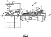
- FIG. 1 schematically illustrates a gas turbine engine 20.
- the gas turbine engine 20 is disclosed herein as a two-spool turbofan that generally incorporates a fan section 22, a compressor section 24, a combustor section 26 and a turbine section 28.
- the fan section 22 drives air along a bypass flow path B in a bypass duct defined within a housing 15 such as a fan case or nacelle, and also drives air along a core flow path C for compression and communication into the combustor section 26 then expansion through the turbine section 28.
- a mid-turbine frame 57 of the engine static structure 36 may be arranged generally between the high pressure turbine 54 and the low pressure turbine 46.
- the mid-turbine frame 57 further supports bearing systems 38 in the turbine section 28.
- the inner shaft 40 and the outer shaft 50 are concentric and rotate via bearing systems 38 about the engine central longitudinal axis A which is collinear with their longitudinal axes.
- the engine 20 bypass ratio is greater than about ten (10:1)
- the fan diameter is significantly larger than that of the low pressure compressor 44
- the low pressure turbine 46 has a pressure ratio that is greater than about five 5:1.
- Low pressure turbine 46 pressure ratio is pressure measured prior to an inlet of low pressure turbine 46 as related to the pressure at the outlet of the low pressure turbine 46 prior to an exhaust nozzle.
- the geared architecture 48 may be an epicycle gear train, such as a planetary gear system or other gear system, with a gear reduction ratio of greater than about 2.3:1 and less than about 5:1. It should be understood, however, that the above parameters are only exemplary of one embodiment of a geared architecture engine and that the present invention is applicable to other gas turbine engines including direct drive turbofans.
- the fan section 22 of the engine 20 is designed for a particular flight condition -- typically cruise at about 0.8 Mach and about 35,000 feet (10,668 meters).
- the flight condition of 0.8 Mach and 35,000 ft (10,668 meters), with the engine at its best fuel consumption - also known as "bucket cruise Thrust Specific Fuel Consumption ('TSFC')" - is the industry standard parameter of lbm of fuel being burned divided by lbf of thrust the engine produces at that minimum point.
- 'TSFC' Thrust Specific Fuel Consumption
- “Low fan pressure ratio” is the pressure ratio across the fan blade alone, without a Fan Exit Guide Vane (“FEGV”) system.
- the low fan pressure ratio as disclosed herein according to one non-limiting embodiment is less than about 1.45, or more narrowly greater than or equal to 1.25.
- Low corrected fan tip speed is the actual fan tip speed in ft/sec divided by an industry standard temperature correction of [(Tram °R) / (518.7 °R)] 0.5 .
- the "Low corrected fan tip speed" as disclosed herein according to one non-limiting embodiment is less than about 1150.0 ft / second (350.5 meters/second), and can be greater than or equal to 1000.0 ft / second (304.8 meters/second).
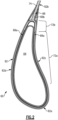
- Figure 2 illustrates a sectioned view of an example airfoil 60 from the turbine section 28 of the engine 20 (see also Figure 1 ).
- the airfoil 60 may be a blade or a vane. It is to be understood that although the examples herein are discussed in context of a turbine airfoil, the examples can also be applied to airfoils in other sections of the engine 20.
- the leg In a wishbone fiber structure in which the arms simply merge into a single leg, the leg may nominally be of equal or lower thickness than the sum of the thickness of the arms. While mechanically strong, this thickness of the single leg may not be desirable in some designs, particularly where cooling holes are to be drilled through the trailing edge to the internal cavity. For instance, the diameter of the cooling hole may exceed or approach the thickness of the single leg and thus require an undesirable condition in which the cooling hole has to be drilled along an interlaminar interface between the single leg and an adjacent fiber layer.
- the thickness also facilitates containment of drilled cooling holes, thereby reducing the chances of causing delamination.
- the stiffness of the thick single leg 66b may also facilitate maintaining the shape of the trailing edge during the preforming process.
- the structure 66 may also facilitate reducing disparities at the free surfaces in the tip of the trailing edge 62b. For instance, a starting fabric may have discontinuities at its edges, where fibers are misaligned or unraveled. If such discontinuities are ultimately located at the tip of the trailing edge, the properties of the tip region may be debited.
- the single leg 66b can initially be over-sized in length and then machined down to the required design length. Such use of the excess sacrificial length of the single leg 66b means that the tip of the trailing edge 62b corresponds to a central portion of the fabric instead of a free edge.
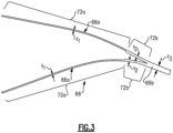
- the third thickness (t3) is greater than the first thickness (t1) by a factor of at least 3, such as by a factor of 3.2 - 4.8.
- the second thickness (t2) is greater than the first thickness (t1) by a factor of at least 1.5, such as by a factor of 1.6 - 2.4.
- the first thickness (t1) may be from approximately 0.005 to 0.015 inches (0.127 to 0.381 mm).
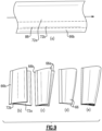
- the weave phase may differ.
- the weft tow 70b of the arm 66a on the left side in Figure 4 extends around the left side of the first (lowest) warp tow 70a column, splits the next warp tow 70a column, extends around to the right of the next warp tow 70a column, and then splits the fourth (top) warp tow 70a column (i.e. left/split/right/split).
- this phase is shifted such that the weft tow 70b is split/right/split/left.
Landscapes
- Engineering & Computer Science (AREA)
- Chemical & Material Sciences (AREA)
- Materials Engineering (AREA)
- Mechanical Engineering (AREA)
- General Engineering & Computer Science (AREA)
- Textile Engineering (AREA)
- Ceramic Engineering (AREA)
- Composite Materials (AREA)
- Manufacturing & Machinery (AREA)
- Chemical Kinetics & Catalysis (AREA)
- Structural Engineering (AREA)
- Organic Chemistry (AREA)
- Physics & Mathematics (AREA)
- Fluid Mechanics (AREA)
- Architecture (AREA)
- Woven Fabrics (AREA)
- Turbine Rotor Nozzle Sealing (AREA)
Applications Claiming Priority (1)
| Application Number | Priority Date | Filing Date | Title |
|---|---|---|---|
| US18/353,196 US12241385B2 (en) | 2023-07-17 | 2023-07-17 | Wishbone fiber layup structure for airfoil |
Publications (1)
| Publication Number | Publication Date |
|---|---|
| EP4494830A1 true EP4494830A1 (fr) | 2025-01-22 |
Family
ID=91946598
Family Applications (1)
| Application Number | Title | Priority Date | Filing Date |
|---|---|---|---|
| EP24188460.0A Pending EP4494830A1 (fr) | 2023-07-17 | 2024-07-12 | Structure de superposition de fibres en forme de bréchet pour profil aérodynamique |
Country Status (2)
| Country | Link |
|---|---|
| US (1) | US12241385B2 (fr) |
| EP (1) | EP4494830A1 (fr) |
Families Citing this family (1)
| Publication number | Priority date | Publication date | Assignee | Title |
|---|---|---|---|---|
| US11920495B1 (en) * | 2023-01-20 | 2024-03-05 | Rtx Corporation | Airfoil with thick wishbone fiber structure |
Citations (5)
| Publication number | Priority date | Publication date | Assignee | Title |
|---|---|---|---|---|
| US20150226071A1 (en) * | 2014-02-12 | 2015-08-13 | Teledyne Scientific & Imaging, Llc | Integral textile structure for 3-d cmc turbine airfoils |
| EP4030037A1 (fr) * | 2021-01-15 | 2022-07-20 | Raytheon Technologies Corporation | Profil aérodynamique à structure fourchue en fibre composite |
| EP4047185A1 (fr) * | 2021-02-23 | 2022-08-24 | Raytheon Technologies Corporation | Aube statorique avec bord formé d'une structure de couches de fibres en forme de triangle |
| EP3911841B1 (fr) * | 2019-01-15 | 2023-03-01 | Safran Aircraft Engines | Aube ou pale d'helice composite pour aeronef avec tissage particulier d'une préforme fibreuse recevant une vessie remplie d'une mousse de conformation |
| EP4403746A1 (fr) * | 2023-01-20 | 2024-07-24 | RTX Corporation | Profil aérodynamique avec structure fibreuse à wishbone épaisse |
Family Cites Families (23)
| Publication number | Priority date | Publication date | Assignee | Title |
|---|---|---|---|---|
| WO1987006901A1 (fr) * | 1986-05-12 | 1987-11-19 | Trimble Brent J | Cadre de bicyclette composite et procede de production |
| FR2861143B1 (fr) | 2003-10-20 | 2006-01-20 | Snecma Moteurs | Aube de turbomachine, notamment aube de soufflante et son procede de fabrication |
| US9062562B2 (en) * | 2008-11-28 | 2015-06-23 | Herakles | Composite material turbomachine engine blade or vane, compressor stator segment or turbine nozzle segment incorporating such vanes and method for manufacturing same |
| US9506355B2 (en) * | 2009-12-14 | 2016-11-29 | Snecma | Turbine engine blade or vane made of composite material, turbine nozzle or compressor stator incorporating such vanes and method of fabricating same |
| FR2953885B1 (fr) * | 2009-12-14 | 2012-02-10 | Snecma | Aube de turbomachine en materiau composite et procede pour sa fabrication |
| US8499450B2 (en) | 2010-01-26 | 2013-08-06 | United Technologies Corporation | Three-dimensionally woven composite blade with spanwise weft yarns |
| US9033673B2 (en) * | 2010-06-28 | 2015-05-19 | Herakles | Turbomachine blade or vane having complementary asymmetrical geometry |
| US9045992B2 (en) * | 2010-06-28 | 2015-06-02 | Herakles | Turbomachine blades or vanes having complementary even/odd geometry |
| US20130011271A1 (en) | 2011-07-05 | 2013-01-10 | United Technologies Corporation | Ceramic matrix composite components |
| US10696008B2 (en) * | 2013-03-15 | 2020-06-30 | Rolls-Royce Corporation | Textile material joining technique |
| US9739259B2 (en) * | 2013-06-05 | 2017-08-22 | The Regents Of The University Of California | Wind turbine blade with biplane section |
| FR3012064B1 (fr) * | 2013-10-23 | 2016-07-29 | Snecma | Preforme fibreuse pour aube creuse de turbomachine |
| FR3032726B1 (fr) | 2015-02-16 | 2017-06-02 | Herakles | Structure fibreuse de renfort de pieces en materiau composite a forte variation d'epaisseur |
| US10590945B2 (en) | 2016-08-10 | 2020-03-17 | United Technologies Corporation | Fiber composite material and preform and fan blade made therefrom |
| EP3318483B1 (fr) * | 2016-11-08 | 2020-12-30 | Ratier-Figeac SAS | Pale d'hélice renforcée |
| US10767502B2 (en) * | 2016-12-23 | 2020-09-08 | Rolls-Royce Corporation | Composite turbine vane with three-dimensional fiber reinforcements |
| US10443410B2 (en) | 2017-06-16 | 2019-10-15 | General Electric Company | Ceramic matrix composite (CMC) hollow blade and method of forming CMC hollow blade |
| US10569481B2 (en) * | 2017-06-26 | 2020-02-25 | General Electric Company | Shaped composite ply layups and methods for shaping composite ply layups |
| US10774008B2 (en) * | 2017-09-21 | 2020-09-15 | General Electric Company | Ceramic matrix composite articles |
| FR3082854B1 (fr) | 2018-06-25 | 2020-09-11 | Safran Ceram | Structure fibreuse et piece en materiau composite incorporant une telle structure |
| US11286792B2 (en) | 2019-07-30 | 2022-03-29 | Rolls-Royce Plc | Ceramic matrix composite vane with cooling holes and methods of making the same |
| US20220090505A1 (en) | 2020-09-22 | 2022-03-24 | General Electric Company | Airfoil having cavity insert to separate flow |
| FR3116466B1 (fr) | 2020-11-25 | 2022-11-25 | Safran Ceram | Préforme fibreuse d'un profil aérodynamique d'aube de turbomachine |
-
2023
- 2023-07-17 US US18/353,196 patent/US12241385B2/en active Active
-
2024
- 2024-07-12 EP EP24188460.0A patent/EP4494830A1/fr active Pending
Patent Citations (5)
| Publication number | Priority date | Publication date | Assignee | Title |
|---|---|---|---|---|
| US20150226071A1 (en) * | 2014-02-12 | 2015-08-13 | Teledyne Scientific & Imaging, Llc | Integral textile structure for 3-d cmc turbine airfoils |
| EP3911841B1 (fr) * | 2019-01-15 | 2023-03-01 | Safran Aircraft Engines | Aube ou pale d'helice composite pour aeronef avec tissage particulier d'une préforme fibreuse recevant une vessie remplie d'une mousse de conformation |
| EP4030037A1 (fr) * | 2021-01-15 | 2022-07-20 | Raytheon Technologies Corporation | Profil aérodynamique à structure fourchue en fibre composite |
| EP4047185A1 (fr) * | 2021-02-23 | 2022-08-24 | Raytheon Technologies Corporation | Aube statorique avec bord formé d'une structure de couches de fibres en forme de triangle |
| EP4403746A1 (fr) * | 2023-01-20 | 2024-07-24 | RTX Corporation | Profil aérodynamique avec structure fibreuse à wishbone épaisse |
Also Published As
| Publication number | Publication date |
|---|---|
| US20250027418A1 (en) | 2025-01-23 |
| US12241385B2 (en) | 2025-03-04 |
Similar Documents
| Publication | Publication Date | Title |
|---|---|---|
| EP4047185B1 (fr) | Aube statorique avec bord formé d'une structure de couches de fibres en forme de triangle | |
| US11920495B1 (en) | Airfoil with thick wishbone fiber structure | |
| US11732597B2 (en) | Double box composite seal assembly with insert for gas turbine engine | |
| EP4283095B1 (fr) | Aube stratifiée en cmc avec gouttes de pli | |
| EP4047184B1 (fr) | Segment d'arc d'aube formé de composite renforcé par des fibres | |
| EP4030037B1 (fr) | Profil aérodynamique à structure fourchue en fibre composite | |
| US11359507B2 (en) | Double box composite seal assembly with fiber density arrangement for gas turbine engine | |
| EP4461928A1 (fr) | Aube avec découpes de pli de cmc pour canaux de refroidissement, moteur à turbine à gaz et procédé de fabrication d'une aube | |
| EP4286656A1 (fr) | Article de moteur à turbine à gaz avec insert en céramique et procédé associé | |
| EP4534802A1 (fr) | Aube, moteur à turbine à gaz et procédé pour fabriquer une aube | |
| US11352897B2 (en) | Double box composite seal assembly for gas turbine engine | |
| US12241385B2 (en) | Wishbone fiber layup structure for airfoil | |
| US12359579B2 (en) | Contour weaves for interwoven vanes | |
| EP4481162A1 (fr) | Profil aérodynamique cmc avec structure de superposition de fibres en forme de wishbone formant une partie de plateforme et de racine | |
| EP4484825A1 (fr) | Chemise de chambre de combustion avec motif de vides dans une couche de fibres en cmc pour des canaux de refroidissement | |
| EP4461925A1 (fr) | Procédé pour surface portante en cmc utilisant un tube central en tissu céramique rigidifié | |
| US12624637B2 (en) | CMC airfoil with circumventing cooling passage | |
| EP4306772B1 (fr) | Multit d'aube de surface portante à couches de fibres entrelacées | |
| EP4008703B1 (fr) | Composant en céramique | |
| EP4015772B1 (fr) | Profil aerodynamique d'une turbine á gaz comprenant un longeron avec passage de plénum encastré |
Legal Events
| Date | Code | Title | Description |
|---|---|---|---|
| PUAI | Public reference made under article 153(3) epc to a published international application that has entered the european phase |
Free format text: ORIGINAL CODE: 0009012 |
|
| STAA | Information on the status of an ep patent application or granted ep patent |
Free format text: STATUS: THE APPLICATION HAS BEEN PUBLISHED |
|
| AK | Designated contracting states |
Kind code of ref document: A1 Designated state(s): AL AT BE BG CH CY CZ DE DK EE ES FI FR GB GR HR HU IE IS IT LI LT LU LV MC ME MK MT NL NO PL PT RO RS SE SI SK SM TR |
|
| STAA | Information on the status of an ep patent application or granted ep patent |
Free format text: STATUS: REQUEST FOR EXAMINATION WAS MADE |
|
| 17P | Request for examination filed |
Effective date: 20250721 |