EP4494878A1 - Dispositif d'impression à jet d'encre et procédé d'impression à jet d'encre - Google Patents
Dispositif d'impression à jet d'encre et procédé d'impression à jet d'encre Download PDFInfo
- Publication number
- EP4494878A1 EP4494878A1 EP22932087.4A EP22932087A EP4494878A1 EP 4494878 A1 EP4494878 A1 EP 4494878A1 EP 22932087 A EP22932087 A EP 22932087A EP 4494878 A1 EP4494878 A1 EP 4494878A1
- Authority
- EP
- European Patent Office
- Prior art keywords
- ink
- reaction liquid
- recording head
- recording
- printing
- Prior art date
- Legal status (The legal status is an assumption and is not a legal conclusion. Google has not performed a legal analysis and makes no representation as to the accuracy of the status listed.)
- Pending
Links
Images






Classifications
-
- B—PERFORMING OPERATIONS; TRANSPORTING
- B41—PRINTING; LINING MACHINES; TYPEWRITERS; STAMPS
- B41M—PRINTING, DUPLICATING, MARKING, OR COPYING PROCESSES; COLOUR PRINTING
- B41M5/00—Duplicating or marking methods; Sheet materials for use therein
- B41M5/0011—Pre-treatment or treatment during printing of the recording material, e.g. heating, irradiating
- B41M5/0017—Application of ink-fixing material, e.g. mordant, precipitating agent, on the substrate prior to printing, e.g. by ink-jet printing, coating or spraying
-
- B—PERFORMING OPERATIONS; TRANSPORTING
- B41—PRINTING; LINING MACHINES; TYPEWRITERS; STAMPS
- B41J—TYPEWRITERS; SELECTIVE PRINTING MECHANISMS, i.e. MECHANISMS PRINTING OTHERWISE THAN FROM A FORME; CORRECTION OF TYPOGRAPHICAL ERRORS
- B41J11/00—Devices or arrangements of selective printing mechanisms, e.g. ink-jet printers or thermal printers, for supporting or handling copy material in sheet or web form
- B41J11/0015—Devices or arrangements of selective printing mechanisms, e.g. ink-jet printers or thermal printers, for supporting or handling copy material in sheet or web form for treating before, during or after printing or for uniform coating or laminating the copy material before or after printing
-
- B—PERFORMING OPERATIONS; TRANSPORTING
- B41—PRINTING; LINING MACHINES; TYPEWRITERS; STAMPS
- B41J—TYPEWRITERS; SELECTIVE PRINTING MECHANISMS, i.e. MECHANISMS PRINTING OTHERWISE THAN FROM A FORME; CORRECTION OF TYPOGRAPHICAL ERRORS
- B41J2/00—Typewriters or selective printing mechanisms characterised by the printing or marking process for which they are designed
- B41J2/005—Typewriters or selective printing mechanisms characterised by the printing or marking process for which they are designed characterised by bringing liquid or particles selectively into contact with a printing material
- B41J2/01—Ink jet
- B41J2/015—Ink jet characterised by the jet generation process
- B41J2/04—Ink jet characterised by the jet generation process generating single droplets or particles on demand
- B41J2/045—Ink jet characterised by the jet generation process generating single droplets or particles on demand by pressure, e.g. electromechanical transducers
- B41J2/04501—Control methods or devices therefor, e.g. driver circuits, control circuits
- B41J2/04551—Control methods or devices therefor, e.g. driver circuits, control circuits using several operating modes
-
- B—PERFORMING OPERATIONS; TRANSPORTING
- B41—PRINTING; LINING MACHINES; TYPEWRITERS; STAMPS
- B41J—TYPEWRITERS; SELECTIVE PRINTING MECHANISMS, i.e. MECHANISMS PRINTING OTHERWISE THAN FROM A FORME; CORRECTION OF TYPOGRAPHICAL ERRORS
- B41J2/00—Typewriters or selective printing mechanisms characterised by the printing or marking process for which they are designed
- B41J2/005—Typewriters or selective printing mechanisms characterised by the printing or marking process for which they are designed characterised by bringing liquid or particles selectively into contact with a printing material
- B41J2/01—Ink jet
- B41J2/015—Ink jet characterised by the jet generation process
- B41J2/04—Ink jet characterised by the jet generation process generating single droplets or particles on demand
- B41J2/045—Ink jet characterised by the jet generation process generating single droplets or particles on demand by pressure, e.g. electromechanical transducers
- B41J2/04501—Control methods or devices therefor, e.g. driver circuits, control circuits
- B41J2/04581—Control methods or devices therefor, e.g. driver circuits, control circuits controlling heads based on piezoelectric elements
-
- B—PERFORMING OPERATIONS; TRANSPORTING
- B41—PRINTING; LINING MACHINES; TYPEWRITERS; STAMPS
- B41J—TYPEWRITERS; SELECTIVE PRINTING MECHANISMS, i.e. MECHANISMS PRINTING OTHERWISE THAN FROM A FORME; CORRECTION OF TYPOGRAPHICAL ERRORS
- B41J2/00—Typewriters or selective printing mechanisms characterised by the printing or marking process for which they are designed
- B41J2/005—Typewriters or selective printing mechanisms characterised by the printing or marking process for which they are designed characterised by bringing liquid or particles selectively into contact with a printing material
- B41J2/01—Ink jet
- B41J2/21—Ink jet for multi-colour printing
- B41J2/2107—Ink jet for multi-colour printing characterised by the ink properties
- B41J2/2114—Ejecting specialized liquids, e.g. transparent or processing liquids
-
- B—PERFORMING OPERATIONS; TRANSPORTING
- B41—PRINTING; LINING MACHINES; TYPEWRITERS; STAMPS
- B41J—TYPEWRITERS; SELECTIVE PRINTING MECHANISMS, i.e. MECHANISMS PRINTING OTHERWISE THAN FROM A FORME; CORRECTION OF TYPOGRAPHICAL ERRORS
- B41J2/00—Typewriters or selective printing mechanisms characterised by the printing or marking process for which they are designed
- B41J2/005—Typewriters or selective printing mechanisms characterised by the printing or marking process for which they are designed characterised by bringing liquid or particles selectively into contact with a printing material
- B41J2/01—Ink jet
- B41J2/21—Ink jet for multi-colour printing
- B41J2/2132—Print quality control characterised by dot disposition, e.g. for reducing white stripes or banding
-
- G—PHYSICS
- G06—COMPUTING OR CALCULATING; COUNTING
- G06K—GRAPHICAL DATA READING; PRESENTATION OF DATA; RECORD CARRIERS; HANDLING RECORD CARRIERS
- G06K15/00—Arrangements for producing a permanent visual presentation of the output data, e.g. computer output printers
- G06K15/02—Arrangements for producing a permanent visual presentation of the output data, e.g. computer output printers using printers
- G06K15/10—Arrangements for producing a permanent visual presentation of the output data, e.g. computer output printers using printers by matrix printers
- G06K15/102—Arrangements for producing a permanent visual presentation of the output data, e.g. computer output printers using printers by matrix printers using ink jet print heads
- G06K15/105—Multipass or interlaced printing
- G06K15/107—Mask selection
Definitions
- Patent Document 1 JP H08-281931A
- Patent Document 1 a case where an image is divided and printed by a multi-pass printing method is not assumed, and there is a concern that an area in which the reaction liquid is printed after the color material ink may be generated depending on a method of dividing the image. As a result, there is a problem that deterioration of image quality due to color bleeding, liquid gathering, or the like is caused.
- the present invention has been made in consideration of the above-described problem, and has as its object to suppress deterioration in image quality in an area printed a plurality of times by a multi-pass printing method.
- the invention described in claim 3 provides the inkjet recording device according to claim 1 or 2, wherein the printing area is an area in which the ejection of the reaction liquid by the second recording head is performed a plurality of times by performing the series of operations a plurality of times.
- the invention of claim 4 is the inkjet recording device according to any one of claims 1 to 3, wherein each of the first recording head and the second recording head is arranged such that the ink ejector and the reaction liquid ejector are arranged in parallel in the first direction, and the controller controls the ejection of the ink by the first recording head and the ejection of the reaction liquid by the second recording head such that the reaction liquid and the ink are able to be ejected at least partially onto a same printing area by at least the series of operations performed once.
- the invention of claim 5 is the inkjet recording device according to any one of claims 1 to 4, wherein
- the invention described in claim 6 relates to the inkjet recording device according to any one of claims 1 to 5, wherein when the ink is ejected a plurality of times in an area in which the ink is ejected a plurality of times by the first recording head, the controller changes a nozzle usage rate of the ink ejector according to a position of the area in the second direction.
- the invention of claim 7 is the inkjet recording device according to any one of claims 1 to 6, wherein each of the reaction liquid and the ink is adjusted so that a surface tension of the reaction liquid ejected from the reaction liquid ejector is lower than a surface tension of the ink ejected from the ink ejector.
- the invention of claim 8 is the inkjet recording device according to any one of claims 1 to 7, wherein the controller may control the ejection of the reaction liquid by the second recording head such that a maximum ejection amount per unit area of the reaction liquid ejected from the reaction liquid ejector increases in a case where the recording medium is an absorbing base material, compared to a case where the recording medium is a non-absorbing base material.
- the present invention it is possible to suppress deterioration of image quality in an area printed a plurality of times by a multi-pass printing method.
- Fig. 1 is a schematic configurational view of an inkjet recording device 1 according to an embodiment of the present invention.
- the inkjet recording device 1 includes a conveyance section 10 to convey the recording medium P in a sub-scanning direction (Y direction in Fig. 1 (second direction)), a carriage 200 on which head units 20Pr, 20Y, 20M, 20C, 20K (also simply referred to as head unit 20) having a plurality of recording heads 21Pr, 21Y, 21M, 21C, and 21K (see Fig. 2 ) (also simply referred to as recording head 21) to eject ink are mounted, a main scanning section 30 to scan the carriage 200 in a main scanning direction (X direction in Fig. 1 (first direction)) intersecting (in the present example, orthogonal to) the sub-scanning direction, a controller 40 ( Fig.
- the recording head 21Pr (second recording head) is a recording head that ejects a reaction liquid for fixing the ink (color material ink) ejected by the recording heads 21Y, 21M, 21C, and 21K (first recording head).
- the conveyance section 10 includes a drive roller 11a, a driven roller 11b, a drive motor 12, and a conveyance belt 13.
- the drive roller 11a and the driven roller 11b rotate about rotation shafts extending in the main scanning direction to cause the conveyance belt 13 to travel around the drive roller 11a and the driven roller 11b.
- the drive roller 11a rotates by an angle proportional to the amount of rotation of a drive motor 12 attached to one end of the drive roller 11a.
- the conveyance belt 13 conveys the recording media P in the sub-scanning direction by circulating around the drive roller 11a and the driven roller 11b with the recording media P placed on the upper surface of the conveyance belt 13.
- the drive motor 12 rotates the drive roller 11a under the control of the controller 40 so that the recording media P are conveyed by predetermined conveyance distances in the sub-scanning direction at predetermined timings.
- the conveyance section 10 includes a rotary encoder (not illustrated) which detects a rotation angle of the drive roller 11a and transmits the detection result to the controller 40.
- the recording medium P it is possible to use various media, such as paper, fabric, or sheet-shaped resin, on the surface of which the ejected ink (color material) can be fixed.
- Fig. 2 is a schematic diagram illustrating an ink ejection face side of the head unit 20 attached to the carriage 200.
- Five head units 20 are attached to the carriage 200.
- the head units 20 eject ink onto the recording medium P placed on the conveyance belt 13 to record an image.
- five head units 20Pr, 20Y, 20M, 20C, and 20K respectively corresponding to the reaction liquid and four color inks (color material inks) of yellow (Y), magenta (M), cyan (C), and black (K) are attached to the carriage 200 in a state of being arranged at predetermined intervals in this order from the + X direction side.
- the head unit 20Y corresponding to yellow ink includes a recording head 21Y attached to an attachment member, a drive circuit (not shown) which is provided in the recording head 21Y and supplies a driving voltage waveform to the recording head 21Y, and a driving control circuit which controls the operation of the drive circuit.
- the drive control circuit supplies pixel data included in image data on an image to be recorded to the drive circuit, and causes the drive circuit to output a drive voltage waveform corresponding to the pixel data.
- the head unit 20Pr corresponding to the reaction liquid and the head units 20M, 20C, and 20K corresponding to the inks of magenta, cyan, and black have recording heads 21Pr, 21M, 21C, and 21K, drive circuits, and drive control circuits, respectively.
- the drive control circuit and the drive circuit provided in each of the head units 20 constitute a drive section 25 (see FIG. 3 ).
- the recording head 21 includes a plurality of recording elements 22.
- the recording element 22 includes a pressure chamber storing ink, a piezoelectric element disposed on the sidewall of the pressure chamber, and a nozzle.
- a drive voltage waveform is supplied from the drive circuit of the recording head 21 to the piezoelectric element, the pressure in the pressure chamber changes according to the drive voltage waveform, and ink is ejected from the nozzle communicating with the pressure chamber.
- the drive control circuit of the drive section 25 causes the drive circuit to output a drive voltage waveform to the recording elements 22 to perform an ejection operation of ejecting an ink from the nozzles of the recording elements 22 by a volume corresponding to pixel data or a non-ejection operation of not ejecting an ink corresponding to pixel data.
- nozzles of the recording elements 22 are provided with opening portions on an ink ejection face of the head unit 20 on the conveyance belt 13 side.
- Fig. 2 is a schematic diagram illustrating the ink ejection face side of the head unit 20 attached to the carriage 200, and some of the openings of the nozzles included in the recording elements 22 are illustrated in a circular shape.
- the plurality of recording elements 22 of the recording head 21 are arranged in a row in the sub-scanning direction to constitute a long head unit 20. These recording heads 21 are arranged in parallel with respect to the main scanning direction.
- the reaction liquid and the four color inks (color material inks) of yellow (Y), magenta (M), cyan (C), and black (K) can be printed in the same printing area by one scanning of the carriage 200 in the main scanning direction.
- each head unit 20 the corresponding recording head is disposed, but in one head unit, the recording heads 21 related to the reaction liquid and the four color inks (color material inks) of yellow (Y), magenta (M), cyan (C), and black (K) may be disposed.
- the recording heads 21 related to the reaction liquid and the four color inks (color material inks) of yellow (Y), magenta (M), cyan (C), and black (K) may be disposed.
- the reaction liquid and the four color inks are adjusted such that the surface tension of the reaction liquid ejected from the nozzles of the recording elements 22 is lower than the surface tension of the four color inks.
- the surface tensions of the reaction liquid and the four color inks are assumed to be 20 mN/m and 30 mN/m, respectively. Accordingly, it is possible to wet and spread the reaction liquid on the entire recording medium P with a ejection amount smaller than that of the four color inks.
- the recording medium P is a non-absorbing base material
- the maximum ejection amount of the reaction liquid per unit area is 1.4 ml/m 2 and the maximum ejection amount of the four color inks per unit area is 9.0 ml/m 2
- the recording medium P is an absorbing base material such as paper
- the reaction liquid is more likely to be absorbed by the recording medium P than when the recording medium P is a non-absorbing base material, and thus it is necessary to increase the maximum ejection amount of the reaction liquid per unit area.
- the maximum ejection amount of the reaction liquid per unit area is 3.6 ml/m 2
- the maximum ejection amount of the four color inks per unit area is 12.0 ml/m 2 .
- the main scanning section 30 includes a pair of carriage rails 31 extending in the main scanning direction and arranged so as to straddle over the conveyance belt 13.
- a carriage 200 is attached to the pair of carriage rails 31 so as to be movable back and forth along the main scanning direction.
- support portions 201 extending from both end portions of the carriage 200 in the sub-scanning direction are respectively placed on the carriage rails 31, and the support portions 201 of the carriage 200 are configured to slide on the carriage rails 31 in the main scanning direction by a linear motor (not shown).
- the main scanning section 30 includes a linear encoder (not shown) which detects the position of the carriage 200 in the main scanning direction and transmits the detection result to the controller 40.
- the ink receiving section 60 is a tray that receives ink ejected from the recording elements 22 of the head units 20 located above the ink receiving section 60 and not used for recording an image on the recording medium P.
- a discarding operation of ejecting the ink from the recording elements 22 of the head unit 20 to the ink receiving section 60 is performed at a predetermined timing during the image recording process or during a period in which the image recording process is not performed.
- a wiping section that wipes the ink ejection face of the head unit 20 positioned above the ink receiving section 60 with a cleaning liquid may be further provided.
- Fig. 3 is a block diagram illustrating a main functional configuration of the inkjet recording device 1.
- the inkjet recording device 1 includes a controller 40 having a central processing section (CPU) 41, a random access memory (RAM) 42, a read only memory (ROM) 43, and a storage section 44, an image processing section 50, an interface 101, the above-described conveyance section 10, the drive section 25 of the head unit 20, and the main scanning section 30.
- the CPU41 is connected to the RAM42, the ROM43, the storage section 44, the conveyance section 10, the drive section 25, the main scanning section 30, the image processing section 50, and the interface 101 via the bus 102.
- the CPU41 performs various arithmetic processing and comprehensively controls the overall operation of the inkjet recording device 1. For example, the CPU41 outputs a control signal to the main scanning section 30 to cause the main scanning section 30 to move the carriage 200 in the main scanning direction at a predetermined timing and speed.
- the CPU41 also performs main scanning control in which, while moving the carriage 200 in the main scanning direction, the CPU41 outputs some of control signals and image data to the drive control circuit of the drive section 25 to cause the drive control circuit to output drive waveform signals in accordance with the image data from the drive circuit to the recording elements 22 so that ink and reaction liquid are ejected from the recording elements 22.
- the CPU41 also performs sub-scanning control by outputting a control signal to the drive motor 12 of the conveyance section 10 at predetermined timings to cause the conveyance section 10 to convey the recording media P by predetermined distances in the sub-scanning direction.
- the RAM 42 provides a working memory space for the CPU 41 and stores temporary data. Note that the RAM42 may include a non-volatile memory.
- the ROM 43 stores various control programs to be executed by the CPU 41, setting data, and the like.
- the setting data includes mask pattern data and the like.
- a rewritable nonvolatile memory such as an electrically erasable programmable read only memory (EEPROM) or a flash memory may be used instead of the ROM 43.
- EEPROM electrically erasable programmable read only memory
- the storage section 44 is composed of a dynamic random access memory (DRAM) or the like, and stores job information including image data input to the controller 40 from the external device 2 via the interface 101. Note that these image data and the like may be stored in the memory RAM42.
- DRAM dynamic random access memory
- the image processing section 50 performs rasterization processing, color conversion processing, gradation correction processing, halftone processing, and the like on the image data stored in the storage section 44 as necessary, and stores the image data in the storage section 44.
- the interface 101 is means for communicating data with the external device 2 and includes various serial interfaces, various parallel interfaces, or a combination of these interfaces.
- the external device 2 is, for example, a personal computer, and supplies image data and the like of an image to be recorded by the inkjet recording device 1 to the controller 40 via the interface 101.
- a main scanning operation in which ink is ejected onto the recording medium P from the recording element group (the plurality of recording elements 22) while the head unit 20 is moved in the main scanning direction and a sub-scanning operation in which the recording medium P is conveyed in the sub-scanning direction are alternately executed, and the image is recorded.
- the printing progress rate of the reaction liquid is higher than the printing progress rate of the ink (color material ink) in each main scanning operation, as described below, in order to suppress dot spreading, liquid gathering, color bleeding, and the like that occur due to the color material ink being printed before the reaction liquid in an area that is a seam between end portions in the sub-scanning direction of image forming areas in which an image is formed by respective main scanning operations.
- the printing progress rate indicates a rate of progress until printing is completed (until a final image is formed) in an area where ink (including reaction liquid) is printed a plurality of times. More specifically, the printing progress rate is a ratio of pixels for which printing has been completed to the total pixels to be printed.
- a main scanning operation in which ink (including reaction liquid) is ejected from the recording element groups onto the recording medium P while the head unit 20 is moved in the main scanning direction is referred to as a "pass", where the "pass” herein refers to only a forward path of movement in the main scanning direction. That is, in the present embodiment, the reaction liquid is ejected and the ink is ejected in the forward path of the movement in the main scanning direction, and the operation of returning the head unit 20 without ejecting the reaction liquid and the ink is performed in the backward path of the movement in the main scanning direction.
- Fig. 4A is a diagram illustrating an example of a printing result in a case where feeding accuracy of a recording medium P in a sub-scanning direction is insufficient
- Fig. 4B is a diagram illustrating an example of a printing result in a case where each nozzle in a head unit 20 has ejection unevenness.
- the seam means a seam between printing areas (bands) adjacent to each other in the sub-scanning direction (see Figs. 4 ).
- the printing area (band) is formed by a plurality of passes (for example, four passes) (refer to FIG. 18 ), it means a seam between an area printed in the fourth pass (last pass) of one printing area and an area printed in the first pass (first pass) of another printing area adjacent to the one printing area.
- the head unit 20K corresponding to black (K) ink will be described as an example.
- FIG. 5 is a diagram illustrating an example of a printing result in a case where seam correction is performed. Note that in Fig. 5 , the head unit 20K corresponding to black (K) ink will be described as an example.
- the printing is performed in a state in which the printing target pixels are thinned out with respect to the portion where the images overlap each other by the printing of the first pass and the printing of the second pass, that is, the portion which is the target of the seam correction.
- the thinning ratio of the printing target pixels is increased from the downstream side to the upstream side in the sub-scanning direction with respect to the seam portion
- the thinning ratio of the printing target pixels is increased from the upstream side to the downstream side in the sub-scanning direction with respect to the seam portion. Accordingly, since it is possible to suppress the density of the image from being increased or decreased at the seam portion, it is possible to make the seam portion inconspicuous.
- the nozzle usage rate of each of the nozzles arranged between the end portion (left) of the head unit 20K on the downstream side in the sub-scanning direction and the position reaching the above-described seam is set to 100%. Furthermore, in printing of the first pass, the nozzle usage rate of each of the nozzles arranged between the position reaching the above-described seam and the end portion (right) of the head unit 20K on the upstream side in the sub-scanning direction is gradually lowered from the position reaching the above-described seam toward the end portion on the upstream side, such that the nozzle usage rate of the nozzles arranged at the end portion on the upstream side is 0%.
- the nozzle usage rate of each of the nozzles arranged between the end portion (right) of the head unit 20K on the upstream side in the sub-scanning direction and the position reaching the seam is set to 100%. Further, in the printing of the second pass, the nozzle usage rate of each of the nozzles arranged between the position reaching the seam and the end portion (left) on the downstream side in the sub-scanning direction of the head unit 20K is gradually decreased from the position reaching the seam toward the end portion on the downstream side so that the nozzle usage rate of the nozzles arranged at the end portion on the downstream side becomes 0%.
- the nozzle usage rate means a rate at which printing is performed without thinning out printing target pixels in one printing operation in a certain target nozzle. That is, the nozzle usage rate can be expressed by the following expression.
- ⁇ Nozzle usage rate > 100% - ⁇ thinning ratio of pixel in main scanning direction (scanning direction) of certain target nozzle >
- Fig. 7 is a diagram illustrating an example of a printing result in a case where image allocation of the seam portion is made different between the reaction liquid and the ink.
- Fig. 8 is a diagram illustrating an example of a printing result in a case where the image allocation of the seam portion is the same between the reaction liquid and the ink.
- the image allocation of the seam portion is made different between the reaction liquid and the ink, the image quality of the seam portion deteriorates, and therefore, it is conceivable that the image allocation of the seam portion is made the same between the reaction liquid and the ink.
- the image allocation of the seam portion is made the same between the reaction liquid and the ink.
- the image quality deteriorates in the seam portion.
- FIG. 9 is a diagram illustrating an example of a printing result in a case where the image allocation of the present embodiment is adopted in the seam portion.
- the reaction liquid in the printing of the reaction liquid in the first pass, the reaction liquid is made to spread over the entirety of the printing target pixels. Accordingly, even in a case where the landing deviation of the ink occurs in each printing of the first pass and the second pass, since there is no portion (pixel) in which the reaction liquid and the ink do not overlap, it is possible to suppress the occurrence of the spreading of the dot, the liquid gathering, the color bleeding, and the like described above.
- reaction liquid spreads over the entirety of the pixels to be printed in the printing of the reaction liquid in the first pass, and for example, as described above, in a case where the surface tension of the reaction liquid ejected from the nozzles of the recording elements 22 is adjusted to be lower than the surface tensions of the four colors of ink, the ejection of the reaction liquid corresponding to all the pixels to be printed may not necessarily be performed. This is because, in such a case, it is possible to cause the reaction liquid to wet and spread over the entire printing target pixel with a smaller ejection amount than that of the four color inks.
- Fig. 10 is a diagram illustrating an example of a printing mode in a case where image allocation is the same between the reaction liquid and the ink when the character image of "B" in the seam portion is printed.
- a character image of "B" is recorded.
- the recording heads 21 for four colors of ink are collectively illustrated as the recording head 21 for color ink (color).
- the main scanning operation for the first time is performed in a state where the recording element 22 provided at the end portion of each recording head 21 on the upstream side in the sub-scanning direction and the end portion of the seam on the upstream side in the sub-scanning direction are located on the same pixel line.
- the reaction liquid is printed according to predetermined image allocation such that the printing progress rate of the seam is 25%, the printing progress rate of an upstream area adjacent to the seam in the sub-scanning direction is 0%, and the printing progress rate of a downstream area adjacent to the seam in the sub-scanning direction is 50%.
- the color ink (color material ink) is printed with the same image allocation as the above-described image allocation relating to the reaction liquid (primer).
- a second (second pass) main scanning operation is performed.
- the reaction liquid is printed with such a predetermined image allocation that a printing progress rate of the seam is 75%, a printing progress rate of an upstream area adjacent to the seam in the sub-scanning direction is 50%, and a printing progress rate of a downstream area adjacent to the seam in the sub-scanning direction is 100%.
- the color ink (color material ink) is printed in the same image allocation as the above-described image allocation for the reaction liquid.
- a third (third pass) main scanning operation is performed in a state where the recording element 22 provided at the end portion of each recording head 21 on the downstream side in the sub-scanning direction and the end portion of the seam on the downstream side in the sub-scanning direction are positioned on the same pixel line by the recording medium P being conveyed to a predetermined position.
- the reaction liquid is printed with such a predetermined image allocation that the printing progress rate of each of the seam whose printing progress rate has not reached 100% and an upstream area adjacent to the seam in the sub-scanning direction becomes 100%.
- the color ink (color material ink) is printed in the same image allocation as the above-described image allocation for the reaction liquid.
- Fig. 11 is a diagram illustrating an example of a printing mode in a case where image allocation is made different between the reaction liquid and the ink when printing a character image of "B" in a seam portion.
- Fig. 11 for example, when the nozzle resolution is 360dpi and the print resolution is 720dpi, three times (three passes) of the main scanning operation (printing) is performed at the seam, and two times (two passes) of the main scanning operation (printing) is performed in the other area so that a character image of "B" is recorded.
- the recording heads 21 for the four color inks are collectively represented as the recording head 21 for the color ink (color).
- the main scanning operation for the first time is performed in a state where the recording element 22 provided at the end portion of each recording head 21 on the upstream side in the sub-scanning direction and the end portion of the seam on the upstream side in the sub-scanning direction are located on the same pixel line.
- the reaction liquid is printed according to predetermined image allocation such that the printing progress rate of the seam is 25%, the printing progress rate of an upstream area adjacent to the seam in the sub-scanning direction is 0%, and the printing progress rate of a downstream area adjacent to the seam in the sub-scanning direction is 50%.
- the color ink (color material ink) is printed with predetermined image allocation such that a printing progress rate of a seam is 25%, a printing progress rate of an upstream area adjacent to the seam in the sub-scanning direction is 0%, and a printing progress rate of a downstream area adjacent to the seam in the sub-scanning direction is 50%, the image allocation being different from the above-described image allocation regarding the reaction liquid.
- a second (second pass) main scanning operation is performed.
- the reaction liquid is printed with such a predetermined image allocation that a printing progress rate of the seam is 75%, a printing progress rate of an upstream area adjacent to the seam in the sub-scanning direction is 50%, and a printing progress rate of a downstream area adjacent to the seam in the sub-scanning direction is 100%.
- the color ink (color material ink) is printed with predetermined image allocation such that a printing progress rate of a seam is 75%, a printing progress rate of an upstream area adjacent to the seam in the sub-scanning direction is 50%, and a printing progress rate of a downstream area adjacent to the seam in the sub-scanning direction is 100%, the image allocation being different from the above-described image allocation relating to the reaction liquid.
- a third (third pass) main scanning operation is performed in a state where the recording element 22 provided at the end portion of each recording head 21 on the downstream side in the sub-scanning direction and the end portion of the seam on the downstream side in the sub-scanning direction are positioned on the same pixel line by the recording medium P being conveyed to a predetermined position.
- the reaction liquid is printed with such a predetermined image allocation that the printing progress rate of each of the seam whose printing progress rate has not reached 100% and an upstream area adjacent to the seam in the sub-scanning direction becomes 100%.
- the color ink (color material ink) is printed in such a predetermined image allocation that a printing progress rate of a seam whose printing progress rate has not yet reached 100% and a printing progress rate of an area adjacent to the seam on the upstream side in the sub-scanning direction become 100%, the image allocation being different from the above-described image allocation regarding the reaction liquid.
- the image allocation being different from the above-described image allocation regarding the reaction liquid.
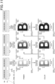
- FIG. 12 is a diagram illustrating an example of a printing mode according to the present embodiment in which a character image of "B" at a seam portion is printed.
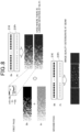
- FIGS. 13A to 13C are graphs showing the nozzle usage rate corresponding to each of the recording elements 22 when the main scanning operation is performed each time (one time to three times) at the seam.
- Fig. 12 for example, when the nozzle resolution is 360dpi and the print resolution is 720dpi, three times (three passes) of the main scanning operation (printing) is performed at the seam, and two times (two passes) of the main scanning operation (printing) is performed in the other area so that a character image of "B" is recorded.
- the recording heads 21 for the four color inks are collectively represented as the recording head 21 for the color ink (color).
- the first main scanning operation (first pass) is performed in a state where the recording element 22 provided at the end portion of each recording head 21 on the upstream side in the sub-scanning direction and the end portion of the seam on the upstream side in the sub-scanning direction are located on the same pixel line.
- the reaction liquid is printed with such a predetermined image allocation that a printing progress rate of the seam is 50%, a printing progress rate of an upstream area adjacent to the seam in the sub-scanning direction is 0%, and a printing progress rate of a downstream area adjacent to the seam in the sub-scanning direction is 50%.
- color ink (color material ink) is printed according to predetermined image allocation such that the printing progress rate of the seam is 25%, the printing progress rate of an upstream area adjacent to the seam in the sub-scanning direction is 0%, and the printing progress rate of a downstream area adjacent to the seam in the sub-scanning direction is 50%.
- the nozzle usage rate of each of the recording elements 22 of the recording head 21Pr for the reaction liquid is adjusted to be 100%.
- the nozzle usage rate of each of the recording elements 22 of the recording heads 21 (21Y, 21M, 21C, and 21K) for the color inks is adjusted so as to decrease from the downstream side to the upstream side in the sub-scanning direction of the seam.
- a second (second pass) main scanning operation is performed.
- the reaction liquid is printed with such a predetermined image allocation that a printing progress rate of the seam is 100%, a printing progress rate of an upstream area adjacent to the seam in the sub-scanning direction is 50%, and a printing progress rate of a downstream area adjacent to the seam in the sub-scanning direction is 100%.
- color ink (color material ink) is printed according to predetermined image allocation such that the printing progress rate of the seam is 75%, the printing progress rate of an upstream area adjacent to the seam in the sub-scanning direction is 50%, and the printing progress rate of a downstream area adjacent to the seam in the sub-scanning direction is 100%.
- the nozzle usage rates of the recording elements 22 of the recording head 21Pr for the reaction liquid and the recording heads 21 (21Y, 21M, 21C, 21K) for the color inks are all adjusted to be 100%.
- a third (third pass) main scanning operation is performed in a state where the recording element 22 provided at the end portion of each recording head 21 on the downstream side in the sub-scanning direction and the end portion of the seam on the downstream side in the sub-scanning direction are positioned on the same pixel line by the recording medium P being conveyed to a predetermined position.
- the reaction liquid is printed with such a predetermined image allocation that the printing progress rate of an upstream side area in the sub-scanning direction adjacent to the seam whose printing progress rate has not reached 100% becomes 100%.
- the color ink (color material ink) is printed in a predetermined image allocation such that the printing progress rate of each of the seam where the printing progress rate has not reached 100% and the area on the upstream side in the sub-scanning direction adjacent to the seam becomes 100%.
- printing of the character image of "B" at the seam portion is completed.
- the nozzle usage rate of each of the recording elements 22 of the recording heads 21 (21Y, 21M, 21C, 21K) for the color inks is adjusted so that the nozzle usage rate of each of the recording elements 22 increases from the downstream side to the upstream side in the sub-scanning direction of the seam. Since the printing of the reaction liquid at the seam is completed by the second main scanning operation, the nozzle usage rate corresponding to each of the recording elements 22 of the recording head 21Pr related to the reaction liquid at the seam is not displayed in FIG. 13C .
- Fig. 14 is a diagram illustrating an example of a printing mode targeting color ink in an area other than a seam.
- This printing mode intended for color ink is characterized in that the same pixel line is printed a plurality of times (for example, twice (two passes)).
- the printing of the fourth pass half of the pixels of each of the pixel lines L4, L8, and L12 are printed with respect to the pixel lines L4, L8, and L 12 so that the printing progress rate becomes 50%.
- the remaining half of the pixels of each of the pixel lines L 1, L5, and L9 are printed with the pixel lines L 1, L5, and L9 as a target such that the printing progress rate becomes 62.5%.
- the remaining half of the pixels of each of the pixel lines L2, L6, and L 10 are printed with the pixel lines L2, L6, and L 10 as a target so that the printing progress rate becomes 75%.
- the remaining half of the pixels of each of the pixel lines L3, L7, and L 11 are printed with the pixel lines L3, L7, and L 11 as a target so that the printing progress rate becomes 87.5%.
- the pixels of the remaining half of each of the pixel lines L4, L8, and L12 are printed with the pixel lines L4, L8, and L 12 as a target so that the printing progress rate becomes 100%.
- Fig. 15 is a diagram illustrating an example of a printing mode targeting a reaction liquid in an area other than a seam.
- the printing mode intended for the reaction liquid is characterized in that the same pixel line is printed at one time.
- the pixel lines L 1, L5, and L9 are printed at once such that the printing progress rate is 25%.
- the pixel lines L2, L6, and L 10 are printed by one time such that the printing progress rate is 50%.
- the pixel lines L3, L7, and L11 are printed at one time such that the printing progress rate is 75%.
- the pixel lines L4, L8, and L12 are printed at one time such that the printing progress rate is 100%. Note that for the fifth pass to the eighth pass, only printing with color ink is performed as illustrated in Fig. 14 .
- FIG. 16 is a diagram illustrating an example of a printing mode in a case where the same pixel line is printed a plurality of times for not only the color ink but also the reaction liquid. Note that in this example, the image allocation of the color ink and the reaction liquid in each printing is the same as each other. Furthermore, in this example, four times (four passes) of main scanning operation (printing) are performed so that a character image of "B" is recorded.
- the nozzle resolution is 360dpi and the print resolution is 720dpi.
- the reaction liquid is printed with a predetermined image allocation such that the printing progress rate is 25%. Subsequently, the color ink is printed with the same image allocation as the above-described image allocation for the reaction liquid.
- second printing is performed. In the second printing, first, the reaction liquid is printed in such a predetermined image allocation that the printing progress rate becomes 50%. Subsequently, the color ink is printed with the same image allocation as the above-described image allocation for the reaction liquid.
- the third printing third pass
- the reaction liquid is printed with the predetermined image allocation such that the printing progress rate is 75%.
- the color ink is printed with the same image allocation as the above-described image allocation for the reaction liquid.
- the fourth printing (fourth pass) is performed.
- the reaction liquid is printed with the predetermined image allocation such that the printing progress rate is 100%.
- the color ink is printed with the same image allocation as the above-described image allocation for the reaction liquid.
- printing of the character image of "B" is completed.
- the printing mode shown in FIG. 16 as described in FIG. 8 , in a case where there is landing deviation between the reaction liquid and the ink, there is a concern that the image quality deteriorates.
- FIG. 17 is a diagram illustrating an example of a printing mode in a case where the same pixel line is printed a plurality of times for not only the color ink but also the reaction liquid. Note that in this example, the image allocation of the color ink and the reaction liquid in each printing is different. Furthermore, in this example, printing (main scanning operation) is performed four times (four passes) so that a character image of "B" is recorded. The nozzle resolution is 360dpi and the print resolution is 720d.
- the reaction liquid is printed with a predetermined image allocation such that the printing progress rate is 25%. Subsequently, the color ink is printed with such a predetermined image allocation that a printing progress rate is 25%, which is different from the above-described image allocation regarding the reaction liquid.
- second printing is performed. In the second printing, first, the reaction liquid is printed in such a predetermined image allocation that the printing progress rate becomes 50%. Subsequently, the color ink is printed with such a predetermined image allocation that a printing progress rate is 50%, which is different from the above-described image allocation regarding the reaction liquid.
- the third printing (third pass) is performed.
- the reaction liquid is printed with the predetermined image allocation such that the printing progress rate is 75%.
- the color ink is printed in such a predetermined image allocation that the printing progress rate becomes 75%, which is different from the above-described image allocation for the reaction liquid.
- the fourth printing (fourth pass) is performed. In the fourth printing, first, the reaction liquid is printed with the predetermined image allocation such that the printing progress rate is 100%.
- the color ink is printed in such a predetermined image allocation that the printing progress rate becomes 100%, which is different from the above-described image allocation for the reaction liquid.
- printing of the character image of "B" is completed. Note that in the printing mode illustrated in Fig. 17 , as described with reference to Fig. 7 , in a case where the image allocation is made different between the reaction liquid and the ink, in each printing, a portion (pixel) where the reaction liquid and the ink do not overlap each other occurs, and therefore, in the portion where only the ink is printed, dot spreading, liquid gathering, color bleeding, and the like occur, and the image quality deteriorates.
- Fig. 18 is a diagram illustrating an example of a printing mode according to the present embodiment in which a character image of "B" in an area other than a seam is printed. Note that in this example, four times (four passes) of main scanning operation (printing) is performed to record a character image of "B".
- the nozzle resolution is 360dpi
- the print resolution is 720dpi in the main scanning direction and 720dpi in the sub-scanning direction.
- printing is completed by the first and second main scanning operations.
- the reaction liquid is printed on half of the pixel lines of all the pixel lines of the printing target area so that the printing progress rate becomes 50%.
- the color ink is printed with such a predetermined image allocation that the printing progress rate is 25%.
- the color ink is printed on the pixel line on which the reaction liquid was printed in the first printing.
- the reaction liquid is printed such that the printing progress rate is 100%, that is, for the remaining half of the pixel lines out of all the pixel lines in the area to be printed.
- the color ink color material ink
- the color ink is printed with a predetermined image allocation such that the printing progress rate is 50%.
- color ink (color material ink) is printed with the predetermined image allocation such that the printing progress rate is 75%. Note that since the printing progress rate of the reaction liquid has reached 100% in the second printing, printing of the reaction liquid is not performed in the third and fourth main scanning operations.
- the inkjet recording device 1 is an inkjet recording device 1 that forms an image with an ink fixed on a recording medium P by repeatedly performing a series of operations of relatively moving recording heads 21Pr, 21Y, 21M, 21C, and 21K and the recording medium P in a sub-scanning direction orthogonal to a main scanning direction after ejecting ink and/or a reaction liquid onto the recording medium P while relatively moving recording heads 21Y, 21M, 21C, and 21K having ink ejectors for ejecting ink onto the recording medium P, and a recording head 21Pr having a reaction liquid ejector for ejecting a reaction liquid for fixing the ink ejected onto the recording medium P, and the recording medium P in a main scanning direction, the inkjet recording device 1 including a controller 40 that controls ejection of ink by the recording heads 21Y, 21M, 21C, and 21K and ejection of a reaction liquid by the recording head 21Pr.
- the controller 40 controls ejection of ink by the recording heads 21Y, 21M, 21C, and 21K and ejection of a reaction liquid by the recording head 21Pr so that a printing progress rate of the reaction liquid by the recording head 21Pr for each of the series of operations is higher than a printing progress rate of the ink by the recording heads 21Y, 21M, 21C, and 21K in a printing area where at least a plurality of times of ejection of ink by the recording heads 21Y, 21M, 21C, and 21K have been performed by performing the series of operations a plurality of times.
- the controller 40 controls the ejection of the ink by the recording heads 21Y, 21M, 21C, and 21K and the ejection of the reaction liquid by the recording head 21Pr so that the ejection of the reaction liquid by the recording head 21Pr is performed before the ejection of the ink by the recording heads 21Y, 21M, 21C, and 21K in the printing area in which the ejection of the ink by the recording heads 21Y, 21M, 21C, and 21K is performed a plurality of times.
- the printing area is an area in which the ejection of the reaction liquid by the recording head 21Pr is performed a plurality of times by performing the series of operations a plurality of times, it is possible to reliably fix the ejected ink to the recording medium P.
- the recording element groups (the plurality of recording elements 22) are arranged in parallel in the main scanning direction, and the controller 40 controls, by at least the above-described series of operations performed once, the ejection of the ink by the recording heads 21Y, 21M, 21C, and 21K and the ejection of the reaction liquid by the recording head 21Pr so that the reaction liquid and the ink can be ejected onto the same printing area. Accordingly, since the carriage 200 can be made compact, it is possible to suppress an increase in the size of the apparatus. In addition, the ejection of the reaction liquid and the ejection of the ink can be efficiently performed.
- the printing area is an area which becomes a seam of an end portion in the sub-scanning direction of an image forming area in which an image is formed by the series of operations performed once, and the number of times of the series of operations is set to be larger in the area which becomes the seam than in other areas.
- the controller 40 changes the nozzle usage rate of the ink ejector (the plurality of recording elements 22) according to the position in the sub-scanning direction of the area, so that the above-described correction processing for color unevenness, streaks, and the like can be more suitably performed.
- the above embodiment is described with the example in which the head unit 20 is scanned in the main scanning operation and the recording medium P is conveyed in the sub-scanning operation, but this is not intended to be limiting.
- the recording medium P may be conveyed in the main scanning direction while the head unit 20 is fixed.
- the recording medium P may be fixed and the head unit 20 may be moved in the sub-scanning direction.
- the above embodiment is described with the example in which the head unit 20 is moved in the + X direction illustrated in Fig. 1 in each main scanning operation, this is not intended to be limiting.
- the movement direction of the head unit 20 may be switched between the + X direction and the - X direction for each main scanning operation.
- a mode may be adopted in which the head unit 20 reciprocates in the + X direction and the-X direction in one main scanning operation. Note that in the case of these modes, head unit 20Pr corresponding to the reaction liquid is arranged on both sides of the carriage 200, that is, on the right side of the head unit 20Y corresponding to the yellow (Y) ink and on the left side of the head unit 20K corresponding to the black (K) ink illustrated in Fig. 1 , respectively.
- each recording head 21 of each of the reaction liquid and the four color inks are arranged in one row in the sub-scanning direction to configure the long head unit 20, but the nozzle row in each recording head 21 is not limited to one row, and may be a plurality of rows.
- each recording head 21 may include a plurality of head chips (long head chips in which the recording elements 22 are arranged in a row in the sub-scanning direction).
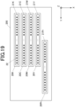
- the recording heads 21 are arranged in parallel in the main scanning direction in the embodiment described above, the recording heads 21 may be configured such that, for example, as illustrated in Fig. 19 , the recording head 21 for the reaction liquid is shifted in the sub-scanning direction relative to the other recording heads 21, that is, the recording heads 21 for the four color inks, whereby some of the recording elements 22 of the recording head 21 for the reaction liquid are arranged in parallel with the recording elements 22 of the recording heads 21 for the four color inks in the main scanning direction.
- reaction liquid and the four color inks (color material inks) of yellow (Y), magenta (M), cyan (C), and black (K) can be printed in the same printing area by one scanning of the carriage 200 in the main scanning direction at a portion where the recording element 22 of the recording head 21 related to the reaction liquid and the recording element 22 of each recording head 21 related to the four color inks are arranged in parallel in the main scanning direction.
- the present invention is applicable to an inkjet recording device and an inkjet recording method.
Landscapes
- Engineering & Computer Science (AREA)
- Quality & Reliability (AREA)
- Physics & Mathematics (AREA)
- Mathematical Physics (AREA)
- General Engineering & Computer Science (AREA)
- General Physics & Mathematics (AREA)
- Theoretical Computer Science (AREA)
- Ink Jet (AREA)
Applications Claiming Priority (1)
| Application Number | Priority Date | Filing Date | Title |
|---|---|---|---|
| PCT/JP2022/012107 WO2023175811A1 (fr) | 2022-03-17 | 2022-03-17 | Dispositif d'impression à jet d'encre et procédé d'impression à jet d'encre |
Publications (2)
| Publication Number | Publication Date |
|---|---|
| EP4494878A1 true EP4494878A1 (fr) | 2025-01-22 |
| EP4494878A4 EP4494878A4 (fr) | 2025-04-23 |
Family
ID=88022629
Family Applications (1)
| Application Number | Title | Priority Date | Filing Date |
|---|---|---|---|
| EP22932087.4A Pending EP4494878A4 (fr) | 2022-03-17 | 2022-03-17 | Dispositif d'impression à jet d'encre et procédé d'impression à jet d'encre |
Country Status (4)
| Country | Link |
|---|---|
| US (1) | US20250178371A1 (fr) |
| EP (1) | EP4494878A4 (fr) |
| JP (1) | JP7786552B2 (fr) |
| WO (1) | WO2023175811A1 (fr) |
Family Cites Families (8)
| Publication number | Priority date | Publication date | Assignee | Title |
|---|---|---|---|---|
| JP3359217B2 (ja) | 1995-02-13 | 2002-12-24 | キヤノン株式会社 | インクジェットプリント装置およびインクジェットプリント方法 |
| JP3190535B2 (ja) * | 1995-02-13 | 2001-07-23 | キヤノン株式会社 | インクジェットプリント装置およびインクジェットプリント方法 |
| WO2013056748A1 (fr) * | 2011-10-21 | 2013-04-25 | Hewlett-Packard Development Company, L.P. | Systèmes et procédés d'impression |
| JP6221509B2 (ja) * | 2013-08-26 | 2017-11-01 | 株式会社リコー | 画像形成装置、画像形成方法及びその画像形成方法により印刷した印刷物、並びに、印刷物の生産方法 |
| JP6432247B2 (ja) * | 2014-09-26 | 2018-12-05 | ブラザー工業株式会社 | インクジェットプリンタ |
| JP7073822B2 (ja) * | 2018-03-19 | 2022-05-24 | 株式会社リコー | 液体吐出装置、処理方法決定装置及び処理方法決定プログラム |
| JP7272000B2 (ja) * | 2019-02-22 | 2023-05-12 | セイコーエプソン株式会社 | インクジェット記録方法及びインクジェット記録装置 |
| JP2021006390A (ja) * | 2019-06-28 | 2021-01-21 | セイコーエプソン株式会社 | インクジェット記録方法及びインクジェット記録装置 |
-
2022
- 2022-03-17 EP EP22932087.4A patent/EP4494878A4/fr active Pending
- 2022-03-17 WO PCT/JP2022/012107 patent/WO2023175811A1/fr not_active Ceased
- 2022-03-17 JP JP2024507331A patent/JP7786552B2/ja active Active
- 2022-03-17 US US18/846,036 patent/US20250178371A1/en active Pending
Also Published As
| Publication number | Publication date |
|---|---|
| JP7786552B2 (ja) | 2025-12-16 |
| WO2023175811A1 (fr) | 2023-09-21 |
| EP4494878A4 (fr) | 2025-04-23 |
| JPWO2023175811A1 (fr) | 2023-09-21 |
| US20250178371A1 (en) | 2025-06-05 |
Similar Documents
| Publication | Publication Date | Title |
|---|---|---|
| US8277020B2 (en) | Liquid ejection method and liquid ejection apparatus | |
| JP7036179B2 (ja) | インクジェット記録装置及びインクジェット記録方法 | |
| JP2011025609A (ja) | 流体噴射装置、及び、流体噴射方法 | |
| US20100231644A1 (en) | Liquid ejection apparatus | |
| JP4193216B2 (ja) | ドット記録方法およびドット記録装置 | |
| US10596824B2 (en) | Image recording apparatus | |
| JP2010149418A (ja) | 液体吐出装置、及び画像形成方法 | |
| JP5157680B2 (ja) | 液体吐出装置、及び、画像形成方法 | |
| US8955934B2 (en) | Fluid ejecting apparatus and fluid ejecting method | |
| EP4494878A1 (fr) | Dispositif d'impression à jet d'encre et procédé d'impression à jet d'encre | |
| US20090262375A1 (en) | Liquid ejecting apparatus and liquid ejecting method | |
| US9944068B2 (en) | Droplet ejection control apparatus, droplet ejection control method, and droplet ejection apparatus | |
| JP5979812B2 (ja) | 画像処理装置および画像処理方法 | |
| US20120194614A1 (en) | Inkjet printing apparatus and inkjet printing method | |
| JP4434714B2 (ja) | 記録装置および記録方法 | |
| JP2020015251A (ja) | 画像記録装置 | |
| JP6885006B2 (ja) | 印刷装置 | |
| JP6546856B2 (ja) | インクジェットプリンター | |
| JP2019181893A (ja) | インクジェット記録装置及び記録方法 | |
| JP5230142B2 (ja) | インクジェット記録装置およびインクジェット記録方法 | |
| US20220016883A1 (en) | Image Recording Apparatus, Image Recording System, Image Recording Method and Non-Transitory Computer Readable Medium Storing Program of Image Recording Method | |
| JP2017132152A (ja) | インクジェットプリンター | |
| JP2026066860A (ja) | インクジェット記録装置およびその制御方法 | |
| JP2019064117A (ja) | 画像記録装置 | |
| JP2007296748A (ja) | 印刷装置、及び印刷方法 |
Legal Events
| Date | Code | Title | Description |
|---|---|---|---|
| STAA | Information on the status of an ep patent application or granted ep patent |
Free format text: STATUS: THE INTERNATIONAL PUBLICATION HAS BEEN MADE |
|
| PUAI | Public reference made under article 153(3) epc to a published international application that has entered the european phase |
Free format text: ORIGINAL CODE: 0009012 |
|
| STAA | Information on the status of an ep patent application or granted ep patent |
Free format text: STATUS: REQUEST FOR EXAMINATION WAS MADE |
|
| 17P | Request for examination filed |
Effective date: 20241010 |
|
| AK | Designated contracting states |
Kind code of ref document: A1 Designated state(s): AL AT BE BG CH CY CZ DE DK EE ES FI FR GB GR HR HU IE IS IT LI LT LU LV MC MK MT NL NO PL PT RO RS SE SI SK SM TR |
|
| A4 | Supplementary search report drawn up and despatched |
Effective date: 20250321 |
|
| RIC1 | Information provided on ipc code assigned before grant |
Ipc: B41J 2/01 20060101AFI20250317BHEP |
|
| P01 | Opt-out of the competence of the unified patent court (upc) registered |
Free format text: CASE NUMBER: APP_17958/2025 Effective date: 20250414 |
|
| DAV | Request for validation of the european patent (deleted) | ||
| DAX | Request for extension of the european patent (deleted) |