EP4495366A1 - Construction composite pour éléments de surface fixes et mobiles - Google Patents
Construction composite pour éléments de surface fixes et mobiles Download PDFInfo
- Publication number
- EP4495366A1 EP4495366A1 EP24187732.3A EP24187732A EP4495366A1 EP 4495366 A1 EP4495366 A1 EP 4495366A1 EP 24187732 A EP24187732 A EP 24187732A EP 4495366 A1 EP4495366 A1 EP 4495366A1
- Authority
- EP
- European Patent Office
- Prior art keywords
- shear
- composite
- profile
- filling
- resistant
- Prior art date
- Legal status (The legal status is an assumption and is not a legal conclusion. Google has not performed a legal analysis and makes no representation as to the accuracy of the status listed.)
- Granted
Links
Images

Classifications
-
- E—FIXED CONSTRUCTIONS
- E06—DOORS, WINDOWS, SHUTTERS, OR ROLLER BLINDS IN GENERAL; LADDERS
- E06B—FIXED OR MOVABLE CLOSURES FOR OPENINGS IN BUILDINGS, VEHICLES, FENCES OR LIKE ENCLOSURES IN GENERAL, e.g. DOORS, WINDOWS, BLINDS, GATES
- E06B3/00—Window sashes, door leaves, or like elements for closing wall or like openings; Layout of fixed or moving closures, e.g. windows in wall or like openings; Features of rigidly-mounted outer frames relating to the mounting of wing frames
- E06B3/04—Wing frames not characterised by the manner of movement
- E06B3/263—Frames with special provision for insulation
- E06B3/26301—Frames with special provision for insulation with prefabricated insulating strips between two metal section members
- E06B3/26303—Frames with special provision for insulation with prefabricated insulating strips between two metal section members with thin strips, e.g. defining a hollow space between the metal section members
-
- E—FIXED CONSTRUCTIONS
- E06—DOORS, WINDOWS, SHUTTERS, OR ROLLER BLINDS IN GENERAL; LADDERS
- E06B—FIXED OR MOVABLE CLOSURES FOR OPENINGS IN BUILDINGS, VEHICLES, FENCES OR LIKE ENCLOSURES IN GENERAL, e.g. DOORS, WINDOWS, BLINDS, GATES
- E06B3/00—Window sashes, door leaves, or like elements for closing wall or like openings; Layout of fixed or moving closures, e.g. windows in wall or like openings; Features of rigidly-mounted outer frames relating to the mounting of wing frames
- E06B3/70—Door leaves
- E06B3/82—Flush doors, i.e. with completely flat surface
- E06B3/86—Flush doors, i.e. with completely flat surface of plastics without an internal frame, e.g. with exterior panels substantially of plastics
-
- E—FIXED CONSTRUCTIONS
- E06—DOORS, WINDOWS, SHUTTERS, OR ROLLER BLINDS IN GENERAL; LADDERS
- E06B—FIXED OR MOVABLE CLOSURES FOR OPENINGS IN BUILDINGS, VEHICLES, FENCES OR LIKE ENCLOSURES IN GENERAL, e.g. DOORS, WINDOWS, BLINDS, GATES
- E06B3/00—Window sashes, door leaves, or like elements for closing wall or like openings; Layout of fixed or moving closures, e.g. windows in wall or like openings; Features of rigidly-mounted outer frames relating to the mounting of wing frames
- E06B3/04—Wing frames not characterised by the manner of movement
- E06B3/263—Frames with special provision for insulation
- E06B3/26301—Frames with special provision for insulation with prefabricated insulating strips between two metal section members
-
- E—FIXED CONSTRUCTIONS
- E06—DOORS, WINDOWS, SHUTTERS, OR ROLLER BLINDS IN GENERAL; LADDERS
- E06B—FIXED OR MOVABLE CLOSURES FOR OPENINGS IN BUILDINGS, VEHICLES, FENCES OR LIKE ENCLOSURES IN GENERAL, e.g. DOORS, WINDOWS, BLINDS, GATES
- E06B3/00—Window sashes, door leaves, or like elements for closing wall or like openings; Layout of fixed or moving closures, e.g. windows in wall or like openings; Features of rigidly-mounted outer frames relating to the mounting of wing frames
- E06B3/04—Wing frames not characterised by the manner of movement
- E06B3/263—Frames with special provision for insulation
- E06B3/26347—Frames with special provision for insulation specially adapted for sliding doors or windows
-
- E—FIXED CONSTRUCTIONS
- E06—DOORS, WINDOWS, SHUTTERS, OR ROLLER BLINDS IN GENERAL; LADDERS
- E06B—FIXED OR MOVABLE CLOSURES FOR OPENINGS IN BUILDINGS, VEHICLES, FENCES OR LIKE ENCLOSURES IN GENERAL, e.g. DOORS, WINDOWS, BLINDS, GATES
- E06B3/00—Window sashes, door leaves, or like elements for closing wall or like openings; Layout of fixed or moving closures, e.g. windows in wall or like openings; Features of rigidly-mounted outer frames relating to the mounting of wing frames
- E06B3/54—Fixing of glass panes or like plates
- E06B3/5454—Fixing of glass panes or like plates inside U-shaped section members
-
- E—FIXED CONSTRUCTIONS
- E06—DOORS, WINDOWS, SHUTTERS, OR ROLLER BLINDS IN GENERAL; LADDERS
- E06B—FIXED OR MOVABLE CLOSURES FOR OPENINGS IN BUILDINGS, VEHICLES, FENCES OR LIKE ENCLOSURES IN GENERAL, e.g. DOORS, WINDOWS, BLINDS, GATES
- E06B3/00—Window sashes, door leaves, or like elements for closing wall or like openings; Layout of fixed or moving closures, e.g. windows in wall or like openings; Features of rigidly-mounted outer frames relating to the mounting of wing frames
- E06B3/04—Wing frames not characterised by the manner of movement
- E06B3/263—Frames with special provision for insulation
- E06B3/26301—Frames with special provision for insulation with prefabricated insulating strips between two metal section members
- E06B3/26305—Connection details
- E06B2003/26316—Disconnectable connections or permitting shifting between the sections
-
- E—FIXED CONSTRUCTIONS
- E06—DOORS, WINDOWS, SHUTTERS, OR ROLLER BLINDS IN GENERAL; LADDERS
- E06B—FIXED OR MOVABLE CLOSURES FOR OPENINGS IN BUILDINGS, VEHICLES, FENCES OR LIKE ENCLOSURES IN GENERAL, e.g. DOORS, WINDOWS, BLINDS, GATES
- E06B3/00—Window sashes, door leaves, or like elements for closing wall or like openings; Layout of fixed or moving closures, e.g. windows in wall or like openings; Features of rigidly-mounted outer frames relating to the mounting of wing frames
- E06B3/04—Wing frames not characterised by the manner of movement
- E06B3/263—Frames with special provision for insulation
- E06B2003/26349—Details of insulating strips
- E06B2003/26369—Specific material characteristics
- E06B2003/2637—Specific material characteristics reinforced
-
- E—FIXED CONSTRUCTIONS
- E06—DOORS, WINDOWS, SHUTTERS, OR ROLLER BLINDS IN GENERAL; LADDERS
- E06B—FIXED OR MOVABLE CLOSURES FOR OPENINGS IN BUILDINGS, VEHICLES, FENCES OR LIKE ENCLOSURES IN GENERAL, e.g. DOORS, WINDOWS, BLINDS, GATES
- E06B3/00—Window sashes, door leaves, or like elements for closing wall or like openings; Layout of fixed or moving closures, e.g. windows in wall or like openings; Features of rigidly-mounted outer frames relating to the mounting of wing frames
- E06B3/70—Door leaves
- E06B2003/7049—Specific panel characteristics
-
- E—FIXED CONSTRUCTIONS
- E06—DOORS, WINDOWS, SHUTTERS, OR ROLLER BLINDS IN GENERAL; LADDERS
- E06B—FIXED OR MOVABLE CLOSURES FOR OPENINGS IN BUILDINGS, VEHICLES, FENCES OR LIKE ENCLOSURES IN GENERAL, e.g. DOORS, WINDOWS, BLINDS, GATES
- E06B3/00—Window sashes, door leaves, or like elements for closing wall or like openings; Layout of fixed or moving closures, e.g. windows in wall or like openings; Features of rigidly-mounted outer frames relating to the mounting of wing frames
- E06B3/54—Fixing of glass panes or like plates
- E06B3/5481—Fixing of glass panes or like plates by means of discrete fixing elements, e.g. glazing clips, glaziers points
-
- E—FIXED CONSTRUCTIONS
- E06—DOORS, WINDOWS, SHUTTERS, OR ROLLER BLINDS IN GENERAL; LADDERS
- E06B—FIXED OR MOVABLE CLOSURES FOR OPENINGS IN BUILDINGS, VEHICLES, FENCES OR LIKE ENCLOSURES IN GENERAL, e.g. DOORS, WINDOWS, BLINDS, GATES
- E06B3/00—Window sashes, door leaves, or like elements for closing wall or like openings; Layout of fixed or moving closures, e.g. windows in wall or like openings; Features of rigidly-mounted outer frames relating to the mounting of wing frames
- E06B3/54—Fixing of glass panes or like plates
- E06B3/58—Fixing of glass panes or like plates by means of borders, cleats, or the like
- E06B3/5807—Fixing of glass panes or like plates by means of borders, cleats, or the like not adjustable
- E06B3/5814—Fixing of glass panes or like plates by means of borders, cleats, or the like not adjustable together with putty or fixed by glue
Definitions
- the present invention relates generally to a composite construction for fixed and movable surface elements, such as windows, doors, panels and facade elements, as well as the fixed or movable surface elements themselves obtainable thereby.
- composite profiles and composite profile frame systems are known from the state of the art. They are preferably made of metal or a metal alloy and can be exposed to adverse weather conditions and strong temperature fluctuations between their inside and outside. A large temperature difference between the outside of the profile frame system, i.e. the side located outside the building, and the inside of the profile frame system generally proves to be problematic in terms of thermal engineering.
- two metal frame profiles are usually connected in such composite profile systems using one or more thermally less conductive plastic insulating bars, also known as separating bars, in order to achieve thermal separation or decoupling between the inside and the outside.
- connection between the two frame profiles and the separating webs must of course simultaneously meet other structural requirements, such as stresses caused by tension or pressure, shear, bending and torsion, and at the same time must satisfy aesthetic requirements, the problem of the so-called bimetallic effect arises as the size increases due to the thermal separation within the connection described above and the simultaneous force-fit connection.
- the bimetallic effect is used when two materials with different thermal expansion coefficients are connected and deformation occurs due to the different expansion.
- Such difficulties due to repeated large temperature differences mainly occur on surface elements in external walls. occurs, for example, in winter between the inside of the room and the outside air, and in summer when solar radiation causes the temperature of the external profile to rise. This deformation is more pronounced the greater the temperature difference between inside and outside, the better the thermal separation between the inside and outside profiles, the larger the dimensions of the windows, doors and facade elements, the more they are exposed to the sun and the better they absorb sunlight and infrared radiation.
- An object of the present invention is to provide a composite profile system for windows, doors and facade elements, especially for movable elements with large dimensions, which reliably prevents the bimetallic effect and thus largely prevents deformation, warping and generally the malfunctions caused thereby in terms of sealing, opening/closing and/or locking.
- a composite construction for fixed and movable surface elements such as windows, doors, panels and facade elements, in particular movable Surface elements
- the composite construction comprises a surface filling, in particular a multiple glazing or a composite panel, with a plurality of first composite profiles as a frame, wherein the first composite profiles each have an outer profile, an inner profile and one or more first separating webs connecting the outer profile and inner profile, wherein the connection of the outer profile and the inner profile is equipped without a slide in the longitudinal direction (e.g. by separating webs that are slideless or attached without a slide).
- the outer profile is attached to an outer side of the edge region of the filling in the longitudinal direction in a first longitudinal section of at most 5% of the length of the outer profile in a shear-resistant manner to the filling, but without shear over the remaining length, e.g. the first longitudinal section represents between 0.1 and 4%, in particular between 1 and 3% of the length of the outer profile (at room temperature).
- the shear-resistant region can be located anywhere along the length/longitudinal direction of the outer profile, it is preferably located at one end or in an end region of the outer profile in order to direct the temperature-related expansion in one direction, with the end region extending at most over a distance of at most 10% of the length of the outer profile.
- this is preferably the lower end or the lower end region.
- this shear-resistant region can be provided at/in the left or right end/end region.
- the inner profile is attached to the filling in a shear-resistant manner against an inner side of an edge region of the filling in the longitudinal direction in a second longitudinal section of at least the length of the first longitudinal section.
- the bimetal effect can lead to a significant warping of the composite profiles, particularly in larger composite structures.
- a shear-free connection of the composite profiles using shear-free dividers should, in theory, largely compensate for this.
- the inventors have found that in practice this is usually only partially successful, since these profiles are not used on their own, but as a frame for a filling that is usually constructed quite differently and usually also represents multiple glazing with a considerable mass.
- the composite structures also usually have tightly fitting sealing profiles between the filling and the profiles, so that it can sometimes lead to uncontrollable sticking, which can result in the non-sliding dividers being able to move against each other progressively due to shearing, which can ultimately cause the composite construction as a whole to warp permanently.
- the frequently required size/height also means that the composite profile on the side of the handle is subjected to very high stress, mainly when closing by central pulling.
- the shear-resistant second length section can make up at least 25%, preferably at least 40% or more than 60% of the length of the inner profile (at room temperature) or even the entire length of the inner profile. If the entire length is not equipped with a shear-free design, the shear-resistant second length section is advantageously divided into several shear-resistant partial length sections, but over essentially the entire length.
- inside and outside are to be understood in such a way that “inside” is the side on which the smallest temperature fluctuations are expected over the period of use, whereas the term “outside” refers to the side opposite the surface of the surface element, i.e. the side that is subject to the greatest temperature differences.
- the filling of the composite construction can be any known type of suitable flat material, e.g. a sandwich panel or multiple glazing.
- the edge area mentioned above can be the outer edge of the filling itself.
- the edge area is preferably an additionally attached surround, e.g. in the form of a U-profile made of suitable plastic, which is placed on the edge area of the multiple glazing if necessary and preferably glued in place.
- Such a surround can be attached during the manufacture of the multiple glazing and thus also reliably protects the glazing from damage during transport to the installation site.
- a shear-resistant connection can be made using suitable means and methods, e.g. by screwing, gluing, form-fitting, etc. It is preferably made using one or more shear-resistant brackets, whereby the shear strength is advantageously achieved by force and/or form-fitting of an appropriately shaped spring on the shear-resistant bracket in a groove in the edge area of the filling.
- the shear-resistant equipment is particularly suitable by means of a toothing of the appropriately shaped spring. If a form-fitting connection is (additionally) desired, the edge area of the filling and/or the groove can have a corresponding counter-toothing.
- a sliding or sliding connection is preferably made by means of one or more sliding brackets spaced apart in the longitudinal direction of the composite profile, whereby the connection of the sliding bracket to the filling is made, for example, by a guide in a groove in the edge area of the filling.
- sliding spring To improve the sliding function, the sliding spring of the slideless mount usually has a rounded cross-section.
- a shear-resistant connection of the outer and inner profiles in the shear-resistant area can also be made simultaneously by a shear-resistant block attached to both profiles.
- the invention further relates to a fixed or movable surface element, such as a window, a door, a panel or a facade element, in particular a movable surface element, comprising at least one composite construction described above.
- a fixed or movable surface element such as a window, a door, a panel or a facade element, in particular a movable surface element, comprising at least one composite construction described above.
- such a composite construction is fixedly or movably mounted in or on a composite frame, wherein the composite frame comprises a plurality of second composite profiles, wherein the second composite profiles each have an outer shell, an inner shell and one or more second separating webs connecting the outer shell and inner shell.
- the invention relates to movable surface elements such as a sliding element in a composite frame, wherein the sliding element has multiple glazing as a filling and wherein a number of rollers are arranged on the underside of the profile construction in a longitudinally distributed manner such that, in use, the sliding element is moved by guiding the rollers on a guide rail attached to the lower part of the composite frame.
- the first separating webs, the second separating webs, the shear-resistant block and/or the enclosure are preferably made of a material selected from the group consisting of polyamide; polyolefin, e.g. polypropylene; polyester, e.g. polyethylene terephthalate or polybutylene terephthalate; acrylonitrile-butadiene-styrene; polyvinyl chloride or mixtures or combinations thereof; if required or desired, the material is fiber-reinforced, e.g. glass fiber reinforced.
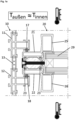
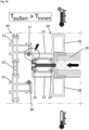
- the Figures 1 and 2 illustrate the bimetal effect that can occur with conventional sliding elements 20 (state of the art), e.g. in the case of a glazed sliding door, whereby the problem is caused by high Temperature differences between the outside and inside and larger dimensions of the sliding elements 20 are increased.
- the Fig. 2a shows on the left a cross section and on the right a longitudinal section through (or a top view of) a conventional composite profile of a sliding element 20 at approximately the same temperatures on the inside and outside, in this case the vertical composite profile 20 towards the opening side of the sliding element.
- the composite profile 20 connects an outer profile 21 to an inner profile 22 firmly/positively to one another via one or more insulating webs 23 designed as a thermal separation, whereby the inner and outer profiles 21, 22 are usually made of metal, e.g. aluminum, and the insulating webs 23 are formed from a plastic material, possibly (glass) fiber reinforced, e.g.
- each of the profiles 21, 22, as well as the separating web 23, has a length L in the longitudinal direction x.
- the outer profile 21 expands by an additional length ⁇ x in the longitudinal direction x.
- the inner profile 22 does not expand (to the same extent) and all elements of the composite are rigidly/force-locked, the composite profile 20 bulges outwards due to the so-called bimetal effect.
- the extent of the bulge ⁇ y in the transverse direction can, however, lead to the sliding element hitting the side part of the profile frame 10 as in Fig.
- Fig. 1a consequently shows a conventional closed sliding element 20 (with double glazing as filling 29) in its frame 10 with small temperature gradients (or no temperature difference) between the outer profile 21 and inner profile 22 of the composite profile of the sliding element 20.
- Both profiles 21, 22 have parts that can serve as handles 25, 26 for operating the sliding element.
- both profiles 21, 22 are rigidly/positively connected by one or more separating webs 23, e.g. by rolling up or forming a collar, etc. These separating webs 23 enable the thermal insulation function of the composite profile 20 because they act as a thermal separation and thus greatly reduce the heat transfer by conduction from the inside to the outside, or from the outside to the inside.
- the frame 10 in which the sliding element 20 can move is in principle constructed in a similar way to a composite profile with an outer frame part 11 and an inner frame part 12 which are thermally separated and connected in a force-locking manner by one or more separating webs 13.
- the frame has a U-shaped cross-section facing the sliding element, in which the outer region of the composite profile of the sliding element 20 is located in the closed state, whereby the wind and heat-tight function can be completed by further aids 17, 18, such as brush, felt or rubber seals.
- Fig. 1b shows the situation in the case of a large temperature difference between the outer and inner profile 21, 22: T outside > T inside .
- the same reference symbols indicate the same elements as in Fig. 1a .
- the cross-section here, again e.g. at half the height of the sliding element 20, shows that the outwardly curved part of the sliding element 20 can no longer be easily guided into the U-shaped cross-section of the frame 10 (see highlighted point in the Fig. 1b ). In other words, the sliding element 20 will hit the frame with its outer profile 21 and possibly damage it or even prevent the complete closing of the Sliding element 20.
- Locking (with locking means not shown here) of the sliding element 20 would therefore possibly even be impossible in this case, as long as the temperature difference between the outer and inner profiles 21, 22 is above a certain value. It may be necessary to wait until this temperature difference has decreased sufficiently, ie until ⁇ y has decreased sufficiently, that the outer profile 21 of the sliding element 20 can be moved back into the U-shaped cross-section of the frame 10. However, damage that has already occurred to the frame 10 or to the composite profile of the sliding element 20 cannot be undone in this way.
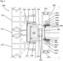
- FIG. 3 an embodiment of the invention is shown using the example of a sliding element 200 in a frame 100 in cross section, wherein the cross section is, for example, approximately halfway up the frame 100.
- the basic elements of the frame 100 and the sliding element 200 are similar to those in the prior art.
- the frame (second composite profile) 100 is formed by an outer shell 111 and an inner shell 112, which are rigidly/positively connected by one or more separating webs 113.
- the frame 100 forms a U-shaped cross-section for receiving the outer edge of the sliding element 200 in the closed state.
- wind and heat sealing aids 117, 118 such as flexible sealing lips, are provided for sealing in the closed state.
- the U-shaped cross-section is preferably provided with a lining plastic profile 115, which is connected to the elements of the frame 100, for example by push-on or clip connections.
- This lining plastic profile 115 can also serve as a stop for the sliding element 200.
- a shock-absorbing lining 116 e.g. a flexible rubber or foam insert.
- the sliding element 200 is also an example of a glazed sliding door, e.g. with triple glazing as filling 290.
- the Composite profile of the sliding element 200 has an outer profile 221 and an inner profile 222, which are connected by one or more separating webs 213.
- separating webs are provided here which are either firmly connected to only one of the two outer and inner profiles 221, 222 and are held on the other profile via a sliding profile, or, as in Fig. 3 as an example, which are two-part or multi-part, with one part being rigidly/positively connected to one of the two profiles and a second part being connected to the other profile, but these two parts are joined together in a sliding manner in the longitudinal direction of the profiles.
- non-sliding dividers in principle enable a certain differential expansion between the outer and inner profiles 221, 222.
- the use of such non-sliding dividers in the composite profiles of the sliding element frame not only results in the flexural rigidity of the composite profiles being generally reduced, but also in the outer and inner profiles being able to move differently in the longitudinal direction x in each of the composite profiles, which can cause the sliding element frame to warp completely or partially.
- the filling 290 of the sliding element 200 e.g. a triple glazing as in Fig. 3 shown
- the inner profile 222 is connected to the frame 261 in a shear-resistant manner on a second length section SF2 (here as an example the sum of the four shown partial length sections SF2 i , ie SF2 a + SF2 b + SF2 c + SF2 d ) of length L, but the outer profile 221 is only connected to the frame 261 in a shear-resistant manner at one point, the first partial section SF1, particularly preferably at one end or an end region E of length L.
- the outer profile 221 On the rest of the length L, the outer profile 221 is always connected to the frame 261 in a shear-free manner.
- the shear-resistant first length section SF1 is preferably located at or near the lower end, ie in the end area E. This means that the outer profile 221 can expand longitudinally sliding towards the filling 290 or the inner profile 222, but in a controlled manner only in one direction, namely upwards. If the inside and outside temperatures equalize again, both profiles 221, 222 are in the same position again. to each other and to the filling 290. A progressive and uncontrolled displacement of the profiles 221, 222 to each other and/or to the filling 290 and consequently the distortion of the sliding element frame is thus avoided.
- the horizontal composite profiles on the upper and lower edges of the sliding element can also be equipped in the same way, with the shear-resistant point (end area) on the outer profile preferably being located on the opening side.
- a (partially) shear-resistant connection of the inner profile 222 to the enclosure 261 of the filling 290 can be made by any known method, e.g. by gluing, screwing, etc.
- the enclosure 261 is preferably connected to the filling 290 by suitable binding agents 265 (in the second length section or the second partial length sections), e.g. glued.
- a (partially) shear-free connection of the enclosed filling can be achieved by simply guiding it within a suitable boundary, but movement transverse to the shear direction must then be prevented as far as possible in another way, e.g. by having the enclosed filling within a U-shaped cross-section of the composite profiles. In practice, however, such a "loose" connection would often be inadequate.
- Preferred shear-free connections can generally be connections with a groove and a corresponding tongue.
- the enclosure 261 has one or more grooves 263, 264 on each side facing the outside and inside in the longitudinal direction, wherein on the inner profile 222 in the second length section SF2 or the second partial length sections SF2i one or more several shear-resistant brackets 242 are attached at several (regularly spaced) locations along the longitudinal direction.
- this can be achieved by roughening or preferably toothing the tongue on the side facing the groove 264, i.e. having a toothing 2422, such as prongs, hooks or claws, which can connect to the material of the enclosure in the groove 264 in a force-fitting and shear-resistant manner.
- the base and/or the side walls of the groove 264 can have a corresponding counter-toothing in order to (additionally) enable shear resistance through positive locking.
- the one or more shear-resistant brackets 242 can be attached by attaching them to the inner profile using suitable fastening means 2424, e.g. by means of screws.
- a shear-resistant connection between the outer profile 221 is only provided at a locally limited point in the longitudinal direction (first length section SF1), e.g. on one to several centimeters. In the case of vertical composite profiles, this point is advantageously at the lower end.
- the locally limited shear-resistant support on this side and its fastening advantageously correspond to those on the inside.
- Another locally limited shear-resistant connection of the outer profile 221 in the first length section SF1 with the enclosure 261 of the filling 290 as mentioned above is of course also possible.
- the cross section in the Fig. 3 (e.g.
- slide-free bracket 241 with a smooth (not toothed) spring, the so-called sliding spring 2411, which is slidably mounted in the longitudinal direction in the groove 263.
- the slide-free bracket 241 can extend over the entire length of the outer profile 221 not taken up by the locally limited slide-resistant bracket 242 just described, or several slide-free brackets 241 can be attached at suitable (regularly spaced) locations along the longitudinal direction.
- the slide-resistant brackets 241, the slide-free brackets 242 and their fastening means 2413, 2424 can be made independently of metal, e.g. steel, aluminum or aluminum alloys, or of (glass) fiber reinforced plastic, similar to those suitable for dividers.
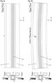
- Fig. 4a and 4b illustrate the invention presented here in the same situations as the prior art in Fig. 2a and 2b .
- the left side shows an embodiment of a (vertical) composite profile according to the invention in cross section with an outer profile 221 and an inner profile 222 which are connected by slideless separating webs.
- the respective right side shows a longitudinal section, in which Fig. 4a the temperature of the outer profile 221 is approximately the same as that of the inner profile 222.
- both profiles are connected to the enclosure (not shown) of the filling with a shear-resistant bracket 242.
- the shear-free connection by the shear-free brackets 241 between the outer profile 221 and the enclosure (not shown) of the filling prevents the bimetallic effect from occurring.
- the outer profile 221 can expand in the longitudinal direction ( ⁇ x) without affecting the connection: the shear-free brackets 241 can move freely in the longitudinal direction with the outer profile 221, regardless of any expansion of the enclosure, but due to the bottom shear-resistant bracket 242 on the outer profile 221, they can only move in the direction (see arrows in Fig. 4b ) at the top (Top).
- the position of the slide-free brackets 241 therefore changes progressively by a distance that is greater the greater the temperature difference and the greater the distance from the slide-resistant bracket 242. If the slide-resistant bracket 242 of the outer profile is located at the lower end as here and the relative movement of the most distant slide-free bracket consequently approaches the linear expansion ⁇ x caused by the temperature difference without the assembly being subjected to warping: the sliding element 200 can be opened and closed easily and reliably even with large temperature differences between the outer and inner profiles.
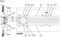
- Fig. 5 a section similar Fig. 4b , with a different/additional shear-resistance of the construction, whereby the cross-section shown on the left in contrast to Fig. 4b bottom (bottom) through the sliding element.
- a shear-resistant block 280 can also be provided, which is fixed to both outer and inner profiles 221, 222, e.g. by means of suitable fastening means 281, such as screws, and thus safely directs the expansion of the outer profile 221 in one direction (e.g. upwards) in the event of large temperature differences.
- this shear-resistant block 280 is preferably made of plastic, e.g. like the (glass) fiber-reinforced polymers and polymulti-mixtures that are usual for dividers.
Landscapes
- Engineering & Computer Science (AREA)
- Civil Engineering (AREA)
- Structural Engineering (AREA)
- Wing Frames And Configurations (AREA)
- Securing Of Glass Panes Or The Like (AREA)
- Joining Of Glass To Other Materials (AREA)
Applications Claiming Priority (1)
| Application Number | Priority Date | Filing Date | Title |
|---|---|---|---|
| LU504779A LU504779B1 (de) | 2023-07-20 | 2023-07-20 | Verbundkonstruktion für feststehende und bewegbare flächenelemente |
Publications (3)
| Publication Number | Publication Date |
|---|---|
| EP4495366A1 true EP4495366A1 (fr) | 2025-01-22 |
| EP4495366B1 EP4495366B1 (fr) | 2025-10-15 |
| EP4495366C0 EP4495366C0 (fr) | 2025-10-15 |
Family
ID=87418939
Family Applications (1)
| Application Number | Title | Priority Date | Filing Date |
|---|---|---|---|
| EP24187732.3A Active EP4495366B1 (fr) | 2023-07-20 | 2024-07-10 | Construction composite pour éléments de surface fixes et mobiles |
Country Status (5)
| Country | Link |
|---|---|
| US (1) | US20250027359A1 (fr) |
| EP (1) | EP4495366B1 (fr) |
| CA (1) | CA3248876A1 (fr) |
| ES (1) | ES3053490T3 (fr) |
| LU (1) | LU504779B1 (fr) |
Families Citing this family (3)
| Publication number | Priority date | Publication date | Assignee | Title |
|---|---|---|---|---|
| USD1086501S1 (en) * | 2023-10-06 | 2025-07-29 | Chelsea Building Products, Inc. | Single hung sill extrusion |
| USD1080924S1 (en) * | 2023-10-06 | 2025-06-24 | Chelsea Building Products, Inc. | Exterior window extrusion |
| USD1080923S1 (en) * | 2023-10-13 | 2025-06-24 | Chelsea Building Products, Inc. | Exterior single hung extrusion for windows |
Citations (4)
| Publication number | Priority date | Publication date | Assignee | Title |
|---|---|---|---|---|
| EP2088276A2 (fr) * | 2008-02-09 | 2009-08-12 | EDUARD HUECK GmbH & CO. KG | Agencement de profilé isolant entre dormant et cadre d'un fênetre ou porte |
| DE102019213920A1 (de) * | 2019-05-20 | 2020-11-26 | Harald Schulz | Außentür oder Fenster |
| FR3099199A1 (fr) * | 2019-07-23 | 2021-01-29 | Groupe Liebot | Ouvrant pour une menuiserie destinée à équiper une baie de bâtiment |
| EP3854982A1 (fr) * | 2020-01-23 | 2021-07-28 | HUECK System GmbH & Co. KG | Battant de porte ainsi que porte dotée d'un cadre et d'un battant de porte |
-
2023
- 2023-07-20 LU LU504779A patent/LU504779B1/de active IP Right Grant
-
2024
- 2024-07-10 EP EP24187732.3A patent/EP4495366B1/fr active Active
- 2024-07-10 ES ES24187732T patent/ES3053490T3/es active Active
- 2024-07-17 CA CA3248876A patent/CA3248876A1/fr active Pending
- 2024-07-18 US US18/776,958 patent/US20250027359A1/en active Pending
Patent Citations (4)
| Publication number | Priority date | Publication date | Assignee | Title |
|---|---|---|---|---|
| EP2088276A2 (fr) * | 2008-02-09 | 2009-08-12 | EDUARD HUECK GmbH & CO. KG | Agencement de profilé isolant entre dormant et cadre d'un fênetre ou porte |
| DE102019213920A1 (de) * | 2019-05-20 | 2020-11-26 | Harald Schulz | Außentür oder Fenster |
| FR3099199A1 (fr) * | 2019-07-23 | 2021-01-29 | Groupe Liebot | Ouvrant pour une menuiserie destinée à équiper une baie de bâtiment |
| EP3854982A1 (fr) * | 2020-01-23 | 2021-07-28 | HUECK System GmbH & Co. KG | Battant de porte ainsi que porte dotée d'un cadre et d'un battant de porte |
Also Published As
| Publication number | Publication date |
|---|---|
| EP4495366B1 (fr) | 2025-10-15 |
| CA3248876A1 (fr) | 2025-06-05 |
| ES3053490T3 (en) | 2026-01-22 |
| US20250027359A1 (en) | 2025-01-23 |
| EP4495366C0 (fr) | 2025-10-15 |
| LU504779B1 (de) | 2025-01-20 |
Similar Documents
| Publication | Publication Date | Title |
|---|---|---|
| EP4495366B1 (fr) | Construction composite pour éléments de surface fixes et mobiles | |
| EP0829609A2 (fr) | Profilé composite calorifuge pour portes, fenêtres ou façades | |
| DE3407639A1 (de) | Verbundstab, insbesondere fuer fensterrahmen, tuerrahmen und rollaeden | |
| EP2228511B1 (fr) | Profilé de seuil en plusieurs parties pour une porte oscillo-battante | |
| WO2016131909A1 (fr) | Dispositif d'étanchéité pour éléments de fenêtre et éléments de porte | |
| EP2666948B1 (fr) | Agencement de cadre pour un panneau de porte sectionnelle | |
| DE102009023883A1 (de) | Fassadenelement | |
| DE102016125602A1 (de) | Isolierkörper für mehrschalige Bauelemente | |
| EP4547928B1 (fr) | Systèmes de cadres en profilés pour éléments coulissants | |
| DE102021105839A1 (de) | Fassadenkonstruktion | |
| DE102016104583A1 (de) | Profilsystem für Flügelelemente von Fassaden | |
| EP4353938A1 (fr) | Système de support en forme de plaque pour le montage en saillie de composants | |
| DE102017117020A1 (de) | Sektionaltorblatt und Sektionaltor mit Sektionaltorblatt | |
| EP3748115B1 (fr) | Seuil pour une porte coulissante | |
| DE202017101034U1 (de) | Fensterbank-Montageelement | |
| DE3134742A1 (de) | "fenster- oder tuerfluegel" | |
| EP2463471B1 (fr) | Procédé de raccordement d'éléments muraux | |
| EP2990581B1 (fr) | Porte ou fenetre presentant des proprietes ignifuges | |
| EP4012147B1 (fr) | Insert de feuillure de verre pour un profilé de cadre de fenêtre et système et procédé de vitrage d'un cadre de fenêtre | |
| CH644667A5 (en) | Casing with window and/or door arranged in brickwork | |
| EP2055884B1 (fr) | Profilé rapporté pour profilé composite pour fenêtres, portes ou analogues et profilé composite doté d'un tel profilé rapporté | |
| EP2039866A2 (fr) | Ouvrant pour fenêtres et portes | |
| DE102009004352A1 (de) | Wärmegedämmte Wandelementeinheit für Gebäudefassaden | |
| EP3385487A1 (fr) | Élément de remplissage pour une façade ou une porte | |
| EP1703064A1 (fr) | Procédé de connecter des fenètres dans une série de fenètres et système de connection |
Legal Events
| Date | Code | Title | Description |
|---|---|---|---|
| PUAI | Public reference made under article 153(3) epc to a published international application that has entered the european phase |
Free format text: ORIGINAL CODE: 0009012 |
|
| STAA | Information on the status of an ep patent application or granted ep patent |
Free format text: STATUS: THE APPLICATION HAS BEEN PUBLISHED |
|
| AK | Designated contracting states |
Kind code of ref document: A1 Designated state(s): AL AT BE BG CH CY CZ DE DK EE ES FI FR GB GR HR HU IE IS IT LI LT LU LV MC ME MK MT NL NO PL PT RO RS SE SI SK SM TR |
|
| STAA | Information on the status of an ep patent application or granted ep patent |
Free format text: STATUS: REQUEST FOR EXAMINATION WAS MADE |
|
| 17P | Request for examination filed |
Effective date: 20250205 |
|
| GRAP | Despatch of communication of intention to grant a patent |
Free format text: ORIGINAL CODE: EPIDOSNIGR1 |
|
| STAA | Information on the status of an ep patent application or granted ep patent |
Free format text: STATUS: GRANT OF PATENT IS INTENDED |
|
| RIC1 | Information provided on ipc code assigned before grant |
Ipc: E06B 3/58 20060101ALN20250516BHEP Ipc: E06B 3/54 20060101ALI20250516BHEP Ipc: E06B 3/263 20060101AFI20250516BHEP |
|
| INTG | Intention to grant announced |
Effective date: 20250616 |
|
| GRAS | Grant fee paid |
Free format text: ORIGINAL CODE: EPIDOSNIGR3 |
|
| GRAA | (expected) grant |
Free format text: ORIGINAL CODE: 0009210 |
|
| STAA | Information on the status of an ep patent application or granted ep patent |
Free format text: STATUS: THE PATENT HAS BEEN GRANTED |
|
| AK | Designated contracting states |
Kind code of ref document: B1 Designated state(s): AL AT BE BG CH CY CZ DE DK EE ES FI FR GB GR HR HU IE IS IT LI LT LU LV MC ME MK MT NL NO PL PT RO RS SE SI SK SM TR |
|
| REG | Reference to a national code |
Ref country code: GB Ref legal event code: FG4D Free format text: NOT ENGLISH Ref country code: CH Ref legal event code: F10 Free format text: ST27 STATUS EVENT CODE: U-0-0-F10-F00 (AS PROVIDED BY THE NATIONAL OFFICE) Effective date: 20251015 |
|
| REG | Reference to a national code |
Ref country code: DE Ref legal event code: R096 Ref document number: 502024000299 Country of ref document: DE |
|
| REG | Reference to a national code |
Ref country code: IE Ref legal event code: FG4D Free format text: LANGUAGE OF EP DOCUMENT: GERMAN |
|
| U01 | Request for unitary effect filed |
Effective date: 20251104 |
|
| U07 | Unitary effect registered |
Designated state(s): AT BE BG DE DK EE FI FR IT LT LU LV MT NL PT RO SE SI Effective date: 20251110 |
|
| REG | Reference to a national code |
Ref country code: ES Ref legal event code: FG2A Ref document number: 3053490 Country of ref document: ES Kind code of ref document: T3 Effective date: 20260122 |
|
| PG25 | Lapsed in a contracting state [announced via postgrant information from national office to epo] |
Ref country code: NO Free format text: LAPSE BECAUSE OF FAILURE TO SUBMIT A TRANSLATION OF THE DESCRIPTION OR TO PAY THE FEE WITHIN THE PRESCRIBED TIME-LIMIT Effective date: 20260115 |
|
| PG25 | Lapsed in a contracting state [announced via postgrant information from national office to epo] |
Ref country code: HR Free format text: LAPSE BECAUSE OF FAILURE TO SUBMIT A TRANSLATION OF THE DESCRIPTION OR TO PAY THE FEE WITHIN THE PRESCRIBED TIME-LIMIT Effective date: 20251015 |
|
| PG25 | Lapsed in a contracting state [announced via postgrant information from national office to epo] |
Ref country code: RS Free format text: LAPSE BECAUSE OF FAILURE TO SUBMIT A TRANSLATION OF THE DESCRIPTION OR TO PAY THE FEE WITHIN THE PRESCRIBED TIME-LIMIT Effective date: 20260115 |
|
| PG25 | Lapsed in a contracting state [announced via postgrant information from national office to epo] |
Ref country code: IS Free format text: LAPSE BECAUSE OF FAILURE TO SUBMIT A TRANSLATION OF THE DESCRIPTION OR TO PAY THE FEE WITHIN THE PRESCRIBED TIME-LIMIT Effective date: 20260215 |