EP4495531A1 - Wärmetauscher und verfahren zur herstellung eines wärmetauschers - Google Patents
Wärmetauscher und verfahren zur herstellung eines wärmetauschers Download PDFInfo
- Publication number
- EP4495531A1 EP4495531A1 EP24765930.3A EP24765930A EP4495531A1 EP 4495531 A1 EP4495531 A1 EP 4495531A1 EP 24765930 A EP24765930 A EP 24765930A EP 4495531 A1 EP4495531 A1 EP 4495531A1
- Authority
- EP
- European Patent Office
- Prior art keywords
- flow passage
- passage member
- heat exchanger
- bonding
- partition wall
- Prior art date
- Legal status (The legal status is an assumption and is not a legal conclusion. Google has not performed a legal analysis and makes no representation as to the accuracy of the status listed.)
- Pending
Links
Images









Classifications
-
- F—MECHANICAL ENGINEERING; LIGHTING; HEATING; WEAPONS; BLASTING
- F28—HEAT EXCHANGE IN GENERAL
- F28D—HEAT-EXCHANGE APPARATUS, NOT PROVIDED FOR IN ANOTHER SUBCLASS, IN WHICH THE HEAT-EXCHANGE MEDIA DO NOT COME INTO DIRECT CONTACT
- F28D9/00—Heat-exchange apparatus having stationary plate-like or laminated conduit assemblies for both heat-exchange media, the media being in contact with different sides of a conduit wall
- F28D9/0062—Heat-exchange apparatus having stationary plate-like or laminated conduit assemblies for both heat-exchange media, the media being in contact with different sides of a conduit wall the conduits for one heat-exchange medium being formed by spaced plates with inserted elements
-
- B—PERFORMING OPERATIONS; TRANSPORTING
- B23—MACHINE TOOLS; METAL-WORKING NOT OTHERWISE PROVIDED FOR
- B23K—SOLDERING OR UNSOLDERING; WELDING; CLADDING OR PLATING BY SOLDERING OR WELDING; CUTTING BY APPLYING HEAT LOCALLY, e.g. FLAME CUTTING; WORKING BY LASER BEAM
- B23K20/00—Non-electric welding by applying impact or other pressure, with or without the application of heat, e.g. cladding or plating
- B23K20/02—Non-electric welding by applying impact or other pressure, with or without the application of heat, e.g. cladding or plating by means of a press ; Diffusion bonding
- B23K20/023—Thermo-compression bonding
-
- B—PERFORMING OPERATIONS; TRANSPORTING
- B23—MACHINE TOOLS; METAL-WORKING NOT OTHERWISE PROVIDED FOR
- B23K—SOLDERING OR UNSOLDERING; WELDING; CLADDING OR PLATING BY SOLDERING OR WELDING; CUTTING BY APPLYING HEAT LOCALLY, e.g. FLAME CUTTING; WORKING BY LASER BEAM
- B23K2101/00—Articles made by soldering, welding or cutting
- B23K2101/04—Tubular or hollow articles
- B23K2101/14—Heat exchangers
-
- F—MECHANICAL ENGINEERING; LIGHTING; HEATING; WEAPONS; BLASTING
- F28—HEAT EXCHANGE IN GENERAL
- F28F—DETAILS OF HEAT-EXCHANGE AND HEAT-TRANSFER APPARATUS, OF GENERAL APPLICATION
- F28F2275/00—Fastening; Joining
- F28F2275/02—Fastening; Joining by using bonding materials; by embedding elements in particular materials
-
- F—MECHANICAL ENGINEERING; LIGHTING; HEATING; WEAPONS; BLASTING
- F28—HEAT EXCHANGE IN GENERAL
- F28F—DETAILS OF HEAT-EXCHANGE AND HEAT-TRANSFER APPARATUS, OF GENERAL APPLICATION
- F28F2275/00—Fastening; Joining
- F28F2275/04—Fastening; Joining by brazing
- F28F2275/045—Fastening; Joining by brazing with particular processing steps, e.g. by allowing displacement of parts during brazing or by using a reservoir for storing brazing material
-
- F—MECHANICAL ENGINEERING; LIGHTING; HEATING; WEAPONS; BLASTING
- F28—HEAT EXCHANGE IN GENERAL
- F28F—DETAILS OF HEAT-EXCHANGE AND HEAT-TRANSFER APPARATUS, OF GENERAL APPLICATION
- F28F3/00—Plate-like or laminated elements; Assemblies of plate-like or laminated elements
- F28F3/02—Elements or assemblies thereof with means for increasing heat-transfer area, e.g. with fins, with recesses, with corrugations
- F28F3/025—Elements or assemblies thereof with means for increasing heat-transfer area, e.g. with fins, with recesses, with corrugations the means being corrugated, plate-like elements
Definitions
- the present disclosure relates to a heat exchanger and a method of manufacturing a heat exchanger.
- PTL 1 discloses a heat exchanger.
- the heat exchanger in PTL 1 has a structure in which a plurality of stages of fluid passages are formed by tube plates (partition wall members) that are stacked on each other with a pair of spacer bars (spacer members) interposed therebetween.
- a corrugated fin is disposed along a direction of flow in the fluid passage.
- a method of manufacturing a heat exchanger for example, there is a method in which constituent members of the heat exchanger are bonded together by brazing.
- a difference of about several tens micrometers in height is generated among the constituent members in layers in the heat exchanger due to variations of thicknesses and press molding of roll materials used as materials of the heat exchanger. Due to this height difference, a space between bonded surfaces of constituent members of the heat exchanger may be not filled with a brazing material, which causes a gap between the bonded surfaces and causes a bonding defect.
- An object of the present disclosure is to provide a method of manufacturing a heat exchanger, the method enabling effective bonding of constituent members of the heat exchanger.
- a first aspect is a method of manufacturing a heat exchanger, the heat exchanger including a plurality of layer members (110) stacked on each other and a partition wall member (120) disposed between the layer members (110) that are adjacent to each other, the plurality of layer members (110) each including a flow passage member (111) configured to form a flow passage for a refrigerant and a spacer member (112) disposed on a side of the flow passage member (111) in a perpendicular direction perpendicular to a stacking direction (V1) of the layer members (110).
- the method of manufacturing the heat exchanger includes a bonding step of bonding the flow passage member (111), the spacer member (112), and the partition wall member (120) together, and at least one of the flow passage member (111) and the spacer member (112) is deformed by the bonding to reduce a dimensional difference in the stacking direction (V1) between the flow passage member (111) and the spacer member (112) that are adjacent to each other in the perpendicular direction.
- a second aspect is the first aspect in which the flow passage member (111), the spacer member (112), and the partition wall member (120) are bonded together in the bonding step by diffusion bonding.
- a third aspect is the second aspect in which a dimension of the flow passage member (111) is larger than a dimension of the spacer member (112) in the stacking direction (V1) before the diffusion bonding, and the flow passage member (111) is deformed by the diffusion bonding to reduce the dimension of the flow passage member (111) in the stacking direction (V1).
- a fourth aspect is the second or third aspect in which a surface pressure at a point of contact between the partition wall member (120) immediately after the diffusion bonding and the flow passage member (111) is 1 MPa or more.
- a fifth aspect is any one of the second to fourth aspects in which the flow passage member (111) has a triangular shape, a trapezoidal shape, a circular shape, or a sinusoidal shape in a cross-sectional view, and the flow passage member is deformed by being pressurized in the diffusion bonding.
- a sixth aspect is any one of the second to fifth aspects in which the flow passage member (111) is bonded at a plurality of bonding portions (YA) to the partition wall member (120) that is one partition wall member by the diffusion bonding, the plurality of bonding portions (YA) are arranged along the perpendicular direction to be spaced from each other, and, when, after the diffusion bonding, a dimension of the bonding portions (YA) in the perpendicular direction, the bonding portions (YA) being adjacent to each other, is P and a dimension of the flow passage member (111) in the stacking direction (V1) is h, a relationship of (2/5)P ⁇ h ⁇ (2/3)P or (2/5)h ⁇ P ⁇ (2/3)h is established.
- a seventh aspect is any one of the second to sixth aspects in which the flow passage member (111) is formed such that a certain unit shape is repeatedly arranged along the perpendicular direction, the flow passage member (111) is bonded at a plurality of bonding portions (YA) to the partition wall member (120) that is one partition wall member by the diffusion bonding, the plurality of bonding portions (YA) are arranged along the perpendicular direction to be spaced from each other, and, when, before the diffusion bonding, a length of a half of the unit shape in a cross-sectional view of a flow passage (R) formed by the flow passage member (111) is L, a dimension of the flow passage member (111) in the stacking direction (V1) is H and when, after the diffusion bonding, a dimension of the flow passage member (111) in the stacking direction (V1) is h, a dimension of each one of the bonding portions (YA) in the perpendicular direction is a, a dimension of the bonding portions (YA) adjacent to each other
- An eighth aspect is a method of manufacturing a heat exchanger, the heat exchanger including a plurality of layer members (110) stacked on each other and a partition wall member (120) disposed between the layer members (110) that are adjacent to each other, the plurality of layer members (110) each including a flow passage member (111) configured to form a flow passage for a refrigerant and a spacer member (112), a plurality of the flow passage members (111) each including a first portion (1111) disposed on a side of the spacer member (112) in a direction perpendicular to a stacking direction (V1) of the layer members (110) and a second portion (1112) sandwiched between the spacer member (112) and the partition wall member (120).
- a flow passage member 111
- V1 stacking direction
- the method of manufacturing the heat exchanger includes a bonding step of bonding the flow passage members (111), the spacer member (112), and the partition wall member (120) together, and at least one of the flow passage members (111) and the spacer member (112) is deformed by the bonding to reduce a dimensional difference in the stacking direction (V1) between a first member and a second member that are adjacent to each other in the perpendicular direction, the first member corresponds to the first portion (1111) of the flow passage member (111), and the second member corresponds to the spacer member (112) and the second portion (1112) of the flow passage member (111).
- a ninth aspect is any one of the first to eighth aspects in which the refrigerant contains propane.
- a tenth aspect is any one of the second to eighth aspects in which a dimension of the flow passage member (111) before the diffusion bonding in the stacking direction (V1) is 2 mm or less.
- An eleventh aspect is any one of the first to third aspects in which an apparent Young's modulus of the flow passage member (111) is smaller than a Young's modulus of the spacer member (112).
- a twelfth aspect is any one of the first to third aspects and the eleventh aspect in which the flow passage member (111) is made of a foamed material.
- a thirteenth aspect is any one of the first to third aspects, the eleventh aspect, and the twelfth aspect in which the flow passage member (111) includes a floor portion (llle) and a projecting portion (llld) projecting from the floor portion (llle), and a dimension of the projecting portion (llld) is smaller than a dimension of the floor portion (llle) in the perpendicular direction.
- a fourteenth aspect is any one of the first to third aspects and the eleventh to thirteenth aspects in which the flow passage member (111) has a hole (111da).
- a fifteenth aspect is the thirteenth aspect in which a portion of the projecting portion (llld) is thinner than another portion of the projecting portion (llld).
- a sixteenth aspect is the thirteenth aspect in which areas of cross-sections of the projecting portion (llld) perpendicular to the stacking direction (V1) are varied.
- a seventeenth aspect is any one of the first to third aspects and the eleventh to sixteenth aspects in which a material of the flow passage member (111) is different from a material of the spacer member (112).
- the material of the flow passage member (111) be different from the material of the spacer member (112) to reduce the apparent Young's modulus of the flow passage member (111).
- An eighteenth aspect is any one of the thirteenth aspect, the fifteenth aspect, and the sixteenth aspect in which a plurality of the projecting portions (llld) project from the floor portion (llle) toward one side (V11) in the stacking direction (V1), the floor portion (llle) is bonded to the partition wall member (120) adjacent on another side (V12) in the stacking direction (V1) to the floor portion (llle), the plurality of projecting portions (llld) are arranged along the perpendicular direction to be spaced from each other and are bonded to the partition wall member (120) adjacent on the one side (V11) in the stacking direction (V1) to the plurality of projecting portions (111d), and a flow passage (R) for a refrigerant is formed among the projecting portions (llld) adjacent to each other, the floor portion (llle), and the partition wall member (120) adjacent on the one side (V11) in the stacking direction (V1) to the projecting portions (llld).
- a heat exchanger in a nineteenth aspect is manufactured by the method of manufacturing the heat exchanger in any one of the first to eighteenth aspects.
- a heat exchanger (1) according to the first embodiment is a device in which heat is exchanged among a plurality of fluids.
- the heat exchanger (1) is made of, for example, a metallic material, such as stainless steel or aluminum.
- the heat exchanger (1) includes a laminate (100), a first plate member (200), and a second plate member (300).
- the laminate (100) includes a plurality of layer members (110) and a partition wall member (120).
- the plurality of layer members (110) are stacked on each other along a first direction (V1).
- the first direction (V1) corresponds to a stacking direction of the layer members (110).
- Each of the plurality of layer members (110) includes a flow passage member (111) and a spacer member (112).
- the flow passage member (111) forms a flow passage for a refrigerant.
- the flow passage member (111) is, for example, a fin.
- the flow passage member (111) includes a mountain portion (111a) protruding toward one side (V11) in the first direction (V1) and a valley portion (111b) protruding toward another side (V12) in the first direction (V1).
- the flow passage member (111) has a corrugated plate shape in which the mountain portion (111a) and the valley portion (111b) are alternately arranged (see Fig. 8(a) and Fig. 8(b) ).
- the spacer member (112) ensures an installation space for the flow passage member (111).
- the spacer member (112) is disposed on a side of the flow passage member (111) in a direction perpendicular to the first direction (V1) (the stacking direction of the layer members (110)).
- a second direction (V2) and a third direction (V3) are defined as directions perpendicular to the first direction (V1).
- the first direction (V1), the second direction (V2), and the third direction (V3) are directions perpendicular to each other.
- the plurality of layer members (110) include two types of layer members.
- the two types of layer members include a first layer member (110A) and a second layer member (110B).
- the first layer member (110A) and the second layer member (110B) are alternately disposed along the first direction (V1).
- the plurality of layer members (110) may include three or more types of layer members, and the three or more types of layer members may be sequentially and repeatedly disposed along the first direction (V1).
- the flow passage member (111) of the first layer member (110A) may be referred to as a first flow passage member (111A), and the flow passage member (111) of the second layer member (110B) may be referred to as a second flow passage member (111B).
- the spacer member (112) of the first layer member (110A) may be referred to as a first spacer member (112A)
- the spacer member (112) of the second layer member (110B) may be referred to as a second spacer member (112B).
- the mountain portion (111a) and the valley portion (111b) of the first flow passage member (111A) extend along the third direction (V3).
- the first flow passage member (111A) sends a refrigerant along the third direction (V3).
- the mountain portion (111a) and the valley portion (111B) of the second flow passage member (111B) extend along the second direction (V2).
- the second flow passage member (111B) sends a refrigerant along the second direction (V2).
- the first flow passage member (111A) and the second flow passage member (111B) send refrigerants in directions perpendicular to each other.
- the direction in which a refrigerant is sent by the first flow passage member (111A) of the first layer member (110A) and the direction in which a refrigerant is sent by the second flow passage member (111B) are not limited.
- the first flow passage member (111A) and the second flow passage member (111B) send different types of refrigerants.
- one of the first flow passage member (111A) and the second flow passage member (111B) sends propane as a refrigerant
- the other flow passage member sends water as a refrigerant.
- one of the first flow passage member (111A) and the second flow passage member (111B) may send propane as a refrigerant while the other flow passage member sends CO 2 as a refrigerant.
- one of the first flow passage member (111A) and the second flow passage member (111B) may send water as a refrigerant while the other flow passage member sends CO 2 as a refrigerant.
- the flow passage member (111) forms a flow passage (R) through which a refrigerant flows.
- a refrigerant that flows through a first flow passage (R1) formed by the first flow passage member (111A) may be referred to as a first refrigerant
- a refrigerant that flows through a second flow passage (R2) formed by the second flow passage member (111B) may be referred to as a second refrigerant.
- the first flow passage (R1) extends along the second direction (V2).
- the second flow passage (R2) extends along the third direction (V3).
- the partition wall member (120) is a flat plate-shaped member.
- the partition wall member (120) is disposed between the layer members (110) that are adjacent to each other.
- the partition wall member (120) is disposed between the first layer member (110A) and the second layer member (110B).
- the first plate member (200) is a flat plate-shaped member.
- the first plate member (200) faces the laminate (100) from the one side (V11) in the first direction (V1).
- the first plate member (200) is located furthest on the one side (V11) (the uppermost stage) in the first direction (V1).
- the second plate member (300) is a flat plate-shaped member.
- the second plate member (300) faces the laminate (100) from the other side (V12) in the first direction (V1).
- the second plate member (300) is located furthest on the other side (V12) (the lowermost stage) in the first direction (V1).
- a pipe member (P) is fixed to an outer surface of the heat exchanger (1).
- the pipe member (P) is fixed to the outer surface of the heat exchanger (1) by, for example, welding (TIG welding).
- the pipe member (P) includes a refrigerant pipe (P1) and a plate-shaped portion (P2).
- the refrigerant pipe (P1) is a tubular member for sending a refrigerant.
- the plate-shaped portion (P2) is a plate-shaped member and is fixed to an outer surface of the heat exchanger (1).
- the refrigerant pipe (P1) is provided on the plate-shaped portion (P2).
- the plate-shaped portion (P2) has a hole through which a refrigerant passes, and the hole is in communication with the inside of the refrigerant pipe (P1) and faces the heat exchanger (1).
- a refrigerant is sent to the heat exchanger (1) through the refrigerant pipe (P1).
- a concave portion (400) is provided at a place on the outer surface of the heat exchanger (1) where the layer members (110) and the partition wall member (120) are located, the pipe member (P) is fixed to an edge portion of the concave portion (400), and the refrigerant pipe (P1) is configured to be in communication with a space between the outer surface of the heat exchanger (1) and the concave portion (400) (see Fig. 5(a) to Fig.
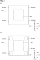
- the first plate member (200) includes a facing portion (201) and a corner portion (202).
- the facing portion (201) faces the flow passage member (111).
- the facing portion (201) is provided at a central portion of the first plate member (200).
- the corner portion (202) includes a first corner portion (2021) to a fourth corner portion (2024), which are provided one each at four corners of the first plate member (200).
- the second plate member (300) includes a facing member (301) and a corner portion (302).
- the facing portion (301) faces the flow passage member (111).
- the facing portion (301) is provided at a central portion of the second plate member (300).
- the corner portion (302) includes a first corner portion (3021) to a fourth corner portion (3024), which are provided one each at four corners of the second plate member (300).
- the first spacer member (112A) includes an arrangement portion (112A1), a corner portion (112A2), a pair of first frame portions (112A3), and a pair of second frame portions (112A4).
- the pair of first frame portions (112A3) extend along the third direction (V3) to be parallel to each other while being spaced apart from each other along the second direction (V2).
- the pair of second frame portions (112A4) extend along the second direction (V2) to be parallel to each other while being spaced apart from each other along the third direction (V3).
- the pair of first frame portions (112A3) and the pair of second frame portions (112A4) form a substantially rectangular frame, and the arrangement portion (112A1) is located on the inner side of the frame.
- the arrangement portion (112A1) is provided for arrangement of the first flow passage member (111A) and is a space extending along the first direction (V1) through the first spacer member (112A).
- the arrangement portion (112A1) is provided at a central portion of the first spacer member (112A).
- the corner portion (112A2) includes a first corner portion (112A21) to a fourth corner portion (112A24), which are provided one each at four corners of the first spacer member (112A).
- the concave portion (400) is formed between the corner portions (112A2) that are adjacent to each other.
- the first frame portions (112A3) and the second frame portions (112A4) are continuous with each other with the corner portions (112A2) interposed therebetween.
- the first flow passage member (111A) is attached to the first frame portions (112A3).
- a gap (Q1) is present between each of the second frame portions (112A4) and the first flow passage member (111A).
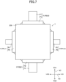
- the second spacer member (112B) includes an arrangement portion (112B1), a corner portion (112B2), a pair of third frame portions (112B3), and a pair of fourth frame portions (112B4).
- the pair of third frame portions (112B3) extend along the third direction (V3) to be parallel to each other while being spaced apart from each other along the second direction (V2).
- the pair of fourth frame portions (112B4) extend along the second direction (V2) to be parallel to each other while being spaced apart from each other along the third direction (V3).
- the pair of third frame portions (112B3) and the pair of fourth frame portions (112B4) form a substantially rectangular frame, and the arrangement portion (112B1) is located on the inner side of the frame.
- the arrangement portion (112B1) is provided for arrangement of the second flow passage member (111B) and is a space extending along the first direction (V1) through the second spacer member (112B).
- the arrangement portion (112B1) is provided at a central portion of the second spacer member (112B).
- the corner portion (112B2) includes a first corner portion (112B21) to a second corner portion (112B24), which are provided one each at four corners of the arrangement portion (112B1).
- the concave portion (400) is formed between the corner portions (112B2) that are adjacent to each other.
- the third frame portions (112B3) and the fourth frame portions (112B4) are continuous with each other with the corner portions (112B2) interposed therebetween.
- the second flow passage member (111B) is attached to the third frame portions (112B3).
- a gap (Q2) is present between each of the fourth frame portions (112B4) and the second flow passage member (111B).
- the partition wall member (120) includes a facing portion (121) and a corner portion (122).
- the facing portion (121) faces the flow passage member (111).
- the facing portion (121) is provided at a central portion of the partition wall member (120).
- the corner portion (122) includes a first corner portion (1221) to a fourth corner portion (1224), which are provided one each at four corners of the facing portion (121).
- the concave portion (400) is formed between the corner portions (122) that are adjacent to each other.
- n-th corner portion (202n) of the first plate member (200), an n-th corner portion (302n) of the second plate member (300), an n-th corner portion (112A2n) of the first spacer member (112A), an n-th corner portion (112B2n) of the second spacer member (112B), and an n-th corner portion (122n) of the partition wall member (120) are disposed to be stacked on each other along the first direction (V1).
- the n is a natural number that is 1 or more and 4 or less.
- end portions (111C) of the second flow passage member (111B) on two sides in the second direction (V2) are each fitted into the groove (112a) formed on the pair of third frame portions (112B3) of the second spacer member (112B), and the second flow passage member (111B) is thereby attached to the second spacer member (112B).
- the pipe member (P) provided in the heat exchanger (1) includes a pair of first pipe members (PA11 and PA12) disposed along the second direction (V2) and a pair of second pipe members (PB21 and PB22) disposed along the third direction (V3).
- the first refrigerant flows into the refrigerant pipe (P1) of the first pipe member (PA11) and is sent to the first flow passage member (111A) through the gap (Q1) after passing through the refrigerant pipe (P1).
- the first refrigerant sent to the first flow passage member (111A) is discharged from the heat exchanger (1) through the refrigerant pipe (P1) of the first pipe member (PA12) after being sent through the first flow passage (R1) of the first flow passage member (111A).
- the second refrigerant flows into the refrigerant pipe (P1) of the second pipe member (PA21) and is sent to the second flow passage member (111B) through the gap (Q2) after passing through the refrigerant pipe (P1).
- the second refrigerant sent to the second flow passage member (111B) is discharged from the heat exchanger (1) through the refrigerant pipe (P1) of the second pipe member (PA22) after being sent through the second flow passage (R2) of the second flow passage member (111B).
- the flow passage member (111) is supported by the spacer member (112).
- the groove (112a) is formed on the spacer member (112), the flow passage member (111) is fitted into (attached to) the groove (112a), and the flow passage member (111) is thereby positioned with respect to the spacer member (112).
- the partition wall member (120) includes a plurality of frame portions disposed around the flow passage member (111), the groove (112a) is formed on each of a pair of frame portions (112A4, 112B3) of the plurality of frame portions facing each other with the flow passage member (111) interposed therebetween, the flow passage member (111) is fitted into the groove (112a), and a gap (Q1, Q2) is provided between each of another pair of frame portions (112A3, 112B4) facing each other with the flow passage member (111) interposed therebetween and the flow passage member (111).
- the groove (112a) has a shape in which a surface facing the flow passage member (111) is recessed.
- a refrigerant is sent to the flow passage member (111) through one of the pair of gaps (Q1, Q2), and a refrigerant is sent to the outside of the flow passage member (111) through the other one of the gaps.
- Each of the plurality of partition wall members (120) is formed of one member in which the plurality of frame portions are connected into an annular form to surround the flow passage member (111).
- the flow passage member (111), the spacer member (112), the partition wall member (120), the first plate member (200), and the second plate member (300) are members that are separated from each other.
- the layer members (110) and the partition wall member (120) before diffusion bonding are illustrated.
- the layer members (110) and the partition wall member (120) after diffusion bonding are illustrated.
- constituent members (the flow passage member (111), the spacer member (112), the partition wall member (120), the first plate member (200), and the second plate member (300)) of the heat exchanger (1) are bonded together by diffusion bonding, brazing, or the like.
- the flow passage member (111), the spacer member (112), and the partition wall member (120) are bonded together by solid phase diffusion bonding.
- the flow passage member (111), the spacer member (112), and the partition wall member (120) may be bonded together by liquid phase diffusion bonding or brazing.
- diffusion bonding in the first embodiment refers to solid phase diffusion bonding.
- the constituent members of the heat exchanger (1) are bonded together by, while the constituent members of the heat exchanger (1) are heated, pressing the constituent members of the heat exchanger (1) along the first direction (V1) to thereby achieve metallic bond between bonded surfaces of the constituent members of the heat exchanger (1).
- At least one of the flow passage member (111) and the spacer member (112) is deformed by the diffusion bonding to reduce a dimensional difference in the first direction (V1) between the flow passage member (111) and the spacer member (112) that are adjacent to each other in a direction perpendicular to the first direction (V1).
- the flow passage member (111) is deformed by the diffusion bonding to reduce the dimension of the flow passage member (111) in the first direction (V1).
- a dimension E1 of the flow passage member (111) is larger than a dimension F1 of the spacer member (112) (E1 > F1) in the first direction (V1).
- the flow passage member (111) has lower rigidity than the spacer member (112). Consequently, it is possible in the diffusion bonding to easily deform the flow passage member (111) and effectively reduce a dimensional difference in the first direction (V1) between the flow passage member (111) and the spacer member (112).
- the surface pressure at the point of contact between the partition wall member (120) immediately after (immediately after deformation) the diffusion bonding (solid phase diffusion bonding) and the flow passage member (111) is 1 MPa or more and is preferably 5 MPa or more. Note that, when the flow passage member (111), the spacer member (112), and the partition wall member (120) are bonded together by liquid phase diffusion bonding, the surface pressure at the point of contact between the partition wall member (120) immediately after the liquid phase diffusion bonding and the flow passage member (111) may be 1 MPa or less.
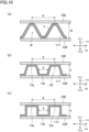
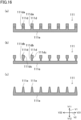
- Fig. 10(a) the laminate (100) and the partition wall member (120) before the diffusion bonding are illustrated.
- Fig. 10(b) a first example of a state of the laminate (100) and the partition wall member (120) after the diffusion bonding is illustrated.
- Fig. 10(c) a second example of a state of the laminate (100) and the partition wall member (120) after the diffusion bonding is illustrated.
- a direction perpendicular to the first direction (V1) may be referred to as a perpendicular direction (V4).
- the perpendicular direction (V4) is the third direction (V3) (see Fig. 8(b) ).
- the perpendicular direction (V4) is the second direction (V2) (see Fig. 8(a) ).
- the flow passage member (111) is bonded at a plurality of bonding portions (YA) to one partition wall member (120) by diffusion bonding, and the plurality of bonding portions (YA) are arranged along the perpendicular direction (V4) to be spaced from each other.
- the dimension of the bonding portions (YA) in the perpendicular direction (V4), the bonding portions (YA) being adjacent to each other is denoted by P and the dimension of the flow passage member (111) in the first direction (V1) is denoted by h.
- the flow passage member (111) is formed such that a constant shape (unit shape) is repeatedly arranged along the perpendicular direction (V4).
- V4 perpendicular direction
- the length of a half of the unit shape in a cross-sectional view is denoted by L and the dimension of the flow passage member (111) in the first direction (V1) is denoted by H.
- the dimension H of the flow passage member (111) before the diffusion bonding is preferably 2 mm or less.
- the flow passage member (111) has a sinusoidal shape (see Fig. 8(a) and Fig. 8(b) ) in a cross-sectional view (when viewed in a direction in which a flow passage formed by the flow passage member (111) extends).
- the present invention is not limited thereto.
- the flow passage member (111) may have a triangular shape, a trapezoidal shape, or a circular shape in a cross-sectional view (when viewed in a direction in which the flow passage extends).
- Fig. 11(a) to Fig. 11(c) the flow passage member (111) may have a triangular shape, a trapezoidal shape, or a circular shape in a cross-sectional view (when viewed in a direction in which the flow passage extends).
- the triangular shape is a shape in which each of the mountain portion (111a) and the valley portion (111b) of the flow passage member (111) is bent at one portion.
- the trapezoidal shape is a shape in which each of the mountain portion (111a) and the valley portion (111b) of the flow passage member (111) is bent at two portions.
- the circular shape is a shape in which a plurality of cylindrical members (111c) are arranged along the perpendicular direction (V4). In this case, the cylindrical members (111c) adjacent to each other may be coupled to each other, or the cylindrical members (111c) adjacent to each other may be separated from each other.
- the flow passage member (111), the spacer member (112), and the partition wall member (120) are bonded together as described above. Consequently, even when a dimensional difference (height difference) in the first direction (V1) is present between the flow passage member (111) and the spacer member (112) that are adjacent to each other in a direction perpendicular to the first direction (V1) before bonding, it is possible to reduce the height difference by deforming at least one of the flow passage member (111) and the spacer member (112) adjacent to each other in the direction perpendicular to the first direction (V1) by using a pressure (pressurization by pressing in the bonding) from the partition wall member (120) in the bonding. As a result, it is possible to effectively bond the constituent members of the heat exchanger (1) together. Further, by effectively bonding the constituent members of the heat exchanger (1), it is possible to suppress an increase in the defect rate of the heat exchanger (1).
- the height difference between the flow passage member (111) and the spacer member (112) adjacent to each other can be reduced by the diffusion bonding, it is not necessary to perform processing of the shapes of the flow passage member (111) and the spacer member (112) in order to match the heights of the flow passage member (111) and the spacer member (112), and it is thus possible to suppress costs for the processing. As a result, it is possible to suppress an increase in the manufacturing costs of the heat exchanger (1).
- the constituent members of the heat exchanger (1) can be made of stainless steel, which is a high-strength material, and leakage of a refrigerant from the heat exchanger (1) can be effectively avoided.
- As an alternative method of diffusion bonding there is brazing using copper as a brazing material. Copper is, however, inferior in strength to stainless steel.
- by making the constituent members of the heat exchanger (1) with stainless steel and bonding the constituent members together by diffusion bonding it is possible to effectively ensure the strength of bonding portions of the constituent members.
- a modification of the heat exchanger (1) includes the laminate (100), the first plate member (200), and the second plate member (300).
- the laminate (100) includes a plurality of layer members (110) and the partition wall member (120).
- Each of the plurality of layer members (110) includes the flow passage member (111) and the spacer member (112).
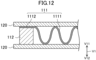
- Fig. 12 is a partial cross-sectional view illustrating a modification of the heat exchanger (1).
- each of a plurality of the flow passage members (111) includes a first portion (1111) and a second portion (1112).
- the first portion (1111) is disposed on a side of the spacer member (112) in a direction perpendicular to the first direction (V1).
- the second portion (1112) is sandwiched between the spacer member (112) and the partition wall member (120).
- the second portion (1112) may be located on the one side (V11) in the first direction (V1) or on the other side (V12) in the first direction (V1) with respect to the spacer member (112).
- the flow passage member (111), the spacer member (112), the partition wall member (120), the first plate member (200), and the second plate member (300) are members that are separated from each other.
- constituent members are bonded together by diffusion bonding.
- At least one of the flow passage member (111) and the spacer member (112) is deformed by the diffusion bonding to reduce a dimensional difference in the first direction (V1) between a first member (the first portion (1111) of the flow passage member (111)) and a second member (the spacer member (112) and the second portion (1112) of the flow passage member (111)) that are adjacent to each other in a direction perpendicular to the first direction (V1).
- the flow passage member (111) is deformed by the diffusion bonding to reduce the dimension of the flow passage member (111) in the first direction (V1).
- the surface pressure at the point of contact between the partition wall member (120) immediately after (immediately after deformation) the diffusion bonding (solid phase diffusion bonding) and the flow passage member (111) is 1 MPa or more and is preferably 5 MPa or more. Note that, when the flow passage member (111), the spacer member (112), and the partition wall member (120) are bonded together by liquid phase diffusion bonding, the surface pressure at the point of contact between the partition wall member (120) immediately after the liquid phase diffusion bonding and the flow passage member (111) may be 1 MPa or less.
- the dimension H of the flow passage member (111) in the first direction (V1) before the diffusion bonding is preferably 2 mm or less.
- a layer member (A) which is at least one layer member (110) of the plurality of layer members (110), may have a plurality of recesses (A2) formed in parallel on one surface (A1) of a flat plate by subjecting the one surface (A1) to processing, such as etching or cutting.
- a portion (A3) where the plurality of recesses (A2) are located corresponds to the flow passage member (111), and a portion (A4) located on each of two sides of the plurality of recesses (A2) corresponds to the spacer member (112).
- the layer member (A) is bonded to the partition wall member (120) by diffusion bonding.
- a space surrounded by each of the recesses (A2) and the partition wall member (120) serves as a flow passage for a refrigerant.
- the heat exchanger (1) includes the laminate (100).
- the laminate (100) includes a plurality of the layer members (110) and the partition wall member (120).
- the plurality of layer members (110) are stacked on each other along the first direction (V1).
- the partition wall member (120) is disposed between the layer members (110) that are adjacent to each other.
- Each of the plurality of layer members (110) includes the flow passage member (111) and the spacer member (112).
- the spacer member (112) is a member that is separated from the flow passage member (111).
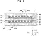
- the spacer member (112) is disposed on a side of the flow passage member (111) in a direction perpendicular to the first direction (V1). In the present embodiment, the spacer member (112) is disposed on each of two sides of the flow passage member (111) in a direction (the second direction (V2)) perpendicular to the first direction (V1).
- the flow passage member (111) includes a plurality of projecting portions (llld) and a floor portion (111e).
- the floor portion (llle) is bonded to the partition wall member (120) adjacent on the other side (V12) in the first direction (V1) to the floor portion (111e).
- Each of the projecting portions (llld) has a bar shape extending along the first direction (V1).
- the thickness (a shape of a cross-section perpendicular to the first direction (V1)) of each of the projecting portions (llld) is constant.
- the plurality of projecting portions (llld) project from the floor portion (llle) toward the one side (V11) in the first direction (V1).
- the plurality of projecting portions (llld) are arranged along the second direction (V2) to be spaced from each other.
- Each of the plurality of projecting portions (llld) extends along the third direction (V3).
- the dimension of each of the plurality of projecting portions (llld) is smaller than the dimension of the floor portion (111e).
- the plurality of projecting portions (llld) include a first projecting portion (111d1), a second projecting portion (111d2), a third projecting portion (111d3), and the like (see Fig. 15(b) ).
- the area of a cross-section of the first projecting portion (111d1) perpendicular to the first direction (V1) is an area (m1)
- the area of a cross-section of the second projecting portion (111d2) perpendicular to the first direction (V1) is an area (m2)
- the area of a cross-section of the third projecting portion (111d3) perpendicular to the first direction (V1) is an area (m3).
- the plurality of projecting portions (llld) are bonded to the partition wall member (120) that is adjacent on the one side (V11) in the first direction (V1) to the plurality of projecting portions (llld).
- the flow passage (R) for a refrigerant is formed among the projecting portions (llld) adjacent to each other in the second direction (V2), the floor portion (llle), and the partition wall member (120) that is adjacent on the one side (V11) in the first direction (V1) to the projecting portions (llld).
- the flow passage (R) extends along the third direction (V3).
- the flow passage member (111) forms a plurality of the flow passages (R) in parallel by three or more projecting portions (llld) arranged to be spaced from each other.
- Fig. 15(a) is a cross-sectional view illustrating the flow passage member (111), the spacer member (112), and the partition wall member (120) before bonding of the partition wall member (120) to the flow passage member (111) and the spacer member (112).
- Fig. 15(b) is a cross-sectional view illustrating the flow passage member (111), the spacer member (112), and the partition wall member (120) after bonding of the partition wall member (120) to the flow passage member (111) and the spacer member (112). As illustrated in Fig.
- the dimension of each of portions of the flow passage member (111) where the projecting portions (llld) are disposed is larger than or equal to the dimension of the spacer member (112) in the first direction (V1).
- the flow passage member (111), the spacer member (112), and the partition wall member (120) are bonded together by diffusion bonding or brazing.
- the diffusion bonding may be either one of solid phase diffusion bonding and liquid phase diffusion bonding. As a result, the heat exchanger (1) is manufactured.
- An apparent Young's modulus G f of the flow passage member (111) is smaller than a Young's modulus G s of the spacer member (112) (G f ⁇ G s ).
- the Young's modulus G s of the spacer member (112) will be described below.
- the Young's modulus G s of the spacer member (112) is the ratio of a sinking deformation rate (U/T) of the spacer member (112) to a load (S/2M) applied to the spacer member (112) in a unit area in the first direction (V1).
- the Young's modulus G s of the spacer member (112) is expressed by Math. 2 below.
- G s ST/2MU
- a pressing force S in Math. 2 is a force (a load applied in a cross-sectional area (M) of the spacer member (112)) that presses the spacer member (112) along the first direction (V1).
- the cross-sectional area (M) is an area of a cross-section (MA) of the spacer member (112) perpendicular to the first direction (V1).
- the dimension T in Math. 2 is a maximum dimension (an initial height of the spacer member (112)) of the spacer member (112) in the first direction (V1) in a state (state before bonding of the partition wall member (120) to the spacer member (112)) in which no external force acts on the spacer member (112).
- U is a deformation amount (sinking deformation amount or contraction amount) of the spacer member (112) in the first direction (V1) when the pressing force S acts on the spacer member (112).
- the apparent Young's modulus G f of the flow passage member (111) is a ratio of a sinking deformation rate (u/t) of the flow passage member (111) to a load (S/ ⁇ m i ) applied to the plurality of projecting portions (llld) in a unit area in the first direction (V1).
- the apparent Young's modulus G f of the flow passage member (111) is expressed by Math. 3 below.
- G f St/ ⁇ m i ⁇ u
- the pressing force S in Math. 3 is a force that presses the flow passage member (111) in the first direction (V1).
- the dimension t in Math. 3 is a maximum dimension (an initial height of the flow passage member (111)) of the flow passage member (111) in the first direction (V1) in a state (a state before bonding of the partition wall member (120) to the flow passage member (111)) in which no external force acts on the flow passage member (111).
- u is a deformation amount (sinking deformation amount or contraction amount) of the flow passage member (111) in the first direction (V1) when the pressing force S acts on the flow passage member (111).
- ⁇ m i is a sum total of average values of the areas of cross-sections of the plurality of projecting portions (llld) perpendicular to the first direction (V1)
- ⁇ m i an average value of areas (m1) of cross-sections of the first projecting portion (111d1) perpendicular to the first direction (V1) + an average value of areas (m2) of cross-sections of the second projecting portion (111d2) perpendicular to the first direction (V1) + an average value of areas (m3) of cross-sections of the third projecting portion (111d3) perpendicular to the first direction (V1) + .
- the cross-section (MA') of the flow passage member (111) is, among cross-sections of the flow passage member (111) perpendicular to the first direction (V1), a cross-section of the floor portion (llle) having a dimension identical to the dimension of the cross-section (MA) of the spacer member (112).
- the imaginary line (D, D1) extending along the first direction (V1) from the first projecting portion (111d1) and the imaginary line (D, D2) extending along the first direction (V1) from the second projecting portion (111d2) intersect the cross-section (MA') of the flow passage member (111).
- intersection projecting portions (W) each having the imaginary line (D) intersecting the cross-section (MA') of the flow passage member (111) in a cross-sectional view
- the plurality of projecting portions (llld) of the flow passage member (111) include two or more intersection projecting portions (W).
- the apparent Young's modulus G f of the flow passage member (111) is smaller than the Young's modulus G s of the spacer member (112) (G f ⁇ G s ). Consequently, as illustrated in Fig. 15(a) and Fig. 15(b) , the flow passage member (111) and the spacer member (112) can be bonded to the partition wall member (120) such that a dimensional difference in the first direction (V1) between the flow passage member (111) and the spacer member (112) is reduced.
- the flow passage member (111) is deformed by bonding such that the dimension of the flow passage member (111) is reduced in the first direction (V1).
- the flow passage member (111) is deformed by bonding to reduce a dimensional difference in the first direction (V1) between the flow passage member (111) and the spacer member (112) that are adjacent to each other in a direction perpendicular to the first direction (V1).
- the flow passage member (111) is deformed by a pressure (pressurization by a press in bonding) from the partition wall member (120) in bonding.
- the dimension of the flow passage member (111) is made to be identical (or substantially identical) to the dimension of the spacer member (112) in the first direction (V1). As a result, it is possible to suppress occurrence of a defect in bonding of the flow passage member (111) and the spacer member (112) to the partition wall member (120).
- the plurality of projecting portions (llld) are thinned such that the flow passage (R) for a refrigerant is formed between the projecting portions (llld) adjacent to each other. Consequently, it is possible to reduce the areas of cross-sections of the plurality of projecting portions (llld) perpendicular to the first direction (V1), and it is thus possible to reduce the apparent Young's modulus G f of the flow passage member (111) to make a state in which the apparent Young's modulus G f of the flow passage member (111) ⁇ the Young's modulus G s of the spacer member (112).
- the flow passage member (111) may be made of a foamed material.
- the foamed material is, for example, foam metal (shooting metal made of aluminum). Consequently, by forming the flow passage member (111) with a foamed material, it is possible to reduce the apparent Young's modulus G f of the flow passage member (111) to make a state in which the apparent Young's modulus G f of the flow passage member (111) ⁇ the Young's modulus G s of the spacer member (112).
- the flow passage member (111) may have a hole (111da).
- the hole (lllda) may be a bottomed hole or may be a hole extending through the flow passage member (111).
- the hole (lllda) is formed in the projecting portion (llld) (at least one projecting portion (llld) of the plurality of projecting portions (111d)).
- a portion of the projecting portion (llld) may be thinner than another portion of the projecting portion (llld).
- a base end portion (111db) of the projecting portion (llld) is thinner than a tip end portion (111dc) of the projecting portion (llld). Consequently, by thinning a portion of the flow passage member (111), it is possible to reduce the apparent Young's modulus G f of the flow passage member (111).
- the areas of cross-sections of the projecting portion (llld) may be varied.
- cross-sections of the projecting portion (llld) perpendicular to the first direction (V1) become smaller toward the one side (V11) in the first direction (V1).
- the projecting portion (llld) becomes thinner toward the one side (V11) in the first direction (V1). Consequently, by varying the thickness of the projecting portion (llld) in the first direction (V1), it is possible to reduce the apparent Young's modulus G f of the flow passage member (111).
- the material of the flow passage member (111) may be different from the material of the spacer member (112).
- the material of the flow passage member (111) is an aluminum alloy containing pure aluminum
- the material of the spacer member (112) is a steel-based material containing pure iron and SUS.
- the material of the flow passage member (111) may be a magnesium alloy containing pure magnesium while the material of the spacer member (112) is a steel-based material containing pure iron and SUS.
- the material of the flow passage member (111) may be a titanium alloy containing pure titanium while the material of the spacer member (112) is a steel-based material containing pure iron and SUS.
- the material of the flow passage member (111) may be a copper alloy containing pure copper while the material of the spacer member (112) is a steel-based material containing pure iron and SUS.
- the material of the flow passage member (111) may be an aluminum alloy containing pure aluminum while the material of the spacer member (112) is a copper alloy containing pure copper.
- the material of the flow passage member (111) may be an aluminum alloy (about 72 GPa) containing pure aluminum while the material of the spacer member (112) is a titanium alloy (about 106 GPa) containing pure titanium.
- the material of the flow passage member (111) may be a magnesium alloy (about 40 GPa) containing pure magnesium while the material of the spacer member (112) is a titanium alloy (about 106 GPa) containing pure titanium.
- the material of the flow passage member (111) may be a magnesium alloy (about 40 GPa) containing pure magnesium while the material of the spacer member (112) is a copper alloy (about 117 GPa) containing pure copper.
- the flow passage member (111) and the spacer member (112) with materials that are different from each other to reduce the apparent Young's modulus G f of the flow passage member (111), in other words, to make a state in which the apparent Young's modulus G f of the flow passage member (111) ⁇ the Young's modulus G s of the spacer member (112).
- the above combination is one example, and the combination of the material of the flow passage member (111) and the material of the spacer member (112) is not limited to the above combination as long as the state in which the apparent Young's modulus G f of the flow passage member (111) ⁇ the Young's modulus G s of the spacer member (112) is established by the combination.
- the apparent Young's modulus G f of the flow passage member (111) is smaller than the Young's modulus G s of the spacer member (112) (G f ⁇ G s ).
- the present disclosure is useful for a heat exchanger and a method of manufacturing a heat exchanger.
Landscapes
- Engineering & Computer Science (AREA)
- Mechanical Engineering (AREA)
- Physics & Mathematics (AREA)
- Thermal Sciences (AREA)
- General Engineering & Computer Science (AREA)
- Heat-Exchange Devices With Radiators And Conduit Assemblies (AREA)
- Pressure Welding/Diffusion-Bonding (AREA)
Applications Claiming Priority (2)
| Application Number | Priority Date | Filing Date | Title |
|---|---|---|---|
| JP2023093232 | 2023-06-06 | ||
| PCT/JP2024/020759 WO2024253170A1 (ja) | 2023-06-06 | 2024-06-06 | 熱交換器及び熱交換器の製造方法 |
Publications (2)
| Publication Number | Publication Date |
|---|---|
| EP4495531A1 true EP4495531A1 (de) | 2025-01-22 |
| EP4495531A4 EP4495531A4 (de) | 2025-08-06 |
Family
ID=92816624
Family Applications (1)
| Application Number | Title | Priority Date | Filing Date |
|---|---|---|---|
| EP24765930.3A Pending EP4495531A4 (de) | 2023-06-06 | 2024-06-06 | Wärmetauscher und verfahren zur herstellung eines wärmetauschers |
Country Status (3)
| Country | Link |
|---|---|
| EP (1) | EP4495531A4 (de) |
| JP (2) | JP7678386B2 (de) |
| WO (1) | WO2024253170A1 (de) |
Families Citing this family (1)
| Publication number | Priority date | Publication date | Assignee | Title |
|---|---|---|---|---|
| JP2026001601A (ja) * | 2024-06-19 | 2026-01-07 | ダイキン工業株式会社 | 熱交換器、冷凍装置 |
Family Cites Families (16)
| Publication number | Priority date | Publication date | Assignee | Title |
|---|---|---|---|---|
| GB1205933A (en) * | 1967-01-25 | 1970-09-23 | Clarke Chapman Ltd | Improvements in or relating to plate heat exchangers |
| JPS60238688A (ja) * | 1984-05-11 | 1985-11-27 | Mitsubishi Electric Corp | 熱交換器 |
| JPH038558A (ja) * | 1989-05-22 | 1991-01-16 | Ishikawajima Harima Heavy Ind Co Ltd | プレートフィン熱交換器の製造方法 |
| JPH0463989U (de) | 1990-09-28 | 1992-06-01 | ||
| US6267175B1 (en) | 2000-02-08 | 2001-07-31 | Honeywell International Inc. | Composite heat exchanger having strengthened joints |
| DE10024963A1 (de) * | 2000-05-22 | 2001-12-13 | Heraeus Noblelight Gmbh | Strahlungsanordnung sowie deren Verwendung und Verfahren zur Behandlung von Oberflächen |
| JP2003185377A (ja) | 2001-12-18 | 2003-07-03 | Nissan Motor Co Ltd | プレートフィン式熱交換器 |
| NL1020483C1 (nl) | 2002-04-26 | 2003-10-28 | Oxycell Holding Bv | Warmtewisselaar en werkwijze voor het vervaardigen daarvan. |
| JP2005069499A (ja) | 2003-08-25 | 2005-03-17 | Nissan Motor Co Ltd | プレートフィン式熱交換器 |
| JP2005144523A (ja) * | 2003-11-19 | 2005-06-09 | Mitsubishi Heavy Ind Ltd | ガス圧による拘束治具及びその拘束治具を用いたろう付け方法 |
| JP2006287158A (ja) | 2005-04-05 | 2006-10-19 | Nikon Corp | 気体供給装置、露光装置、及びデバイスの製造方法 |
| US10046379B1 (en) | 2010-01-25 | 2018-08-14 | Robert Greenwood | Heat exchanger fin forming machine |
| JPWO2014125566A1 (ja) * | 2013-02-12 | 2017-02-02 | 三菱電機株式会社 | プレート式熱交換器及び冷凍サイクル装置 |
| US9777970B2 (en) | 2013-08-09 | 2017-10-03 | Hamilton Sundstrand Coporation | Reduced thermal expansion closure bars for a heat exchanger |
| CN109883238A (zh) | 2019-03-08 | 2019-06-14 | 西安交通大学 | 一种板翅式热交换器芯体及其翅片结构 |
| US11679445B2 (en) | 2020-11-12 | 2023-06-20 | Raytheon Company | Ultrasonic additive manufacturing of cold plates with pre-formed fins |
-
2024
- 2024-06-06 WO PCT/JP2024/020759 patent/WO2024253170A1/ja not_active Ceased
- 2024-06-06 JP JP2024092211A patent/JP7678386B2/ja active Active
- 2024-06-06 EP EP24765930.3A patent/EP4495531A4/de active Pending
-
2025
- 2025-04-30 JP JP2025075611A patent/JP2025107593A/ja active Pending
Also Published As
| Publication number | Publication date |
|---|---|
| JP7678386B2 (ja) | 2025-05-16 |
| JP2024175686A (ja) | 2024-12-18 |
| JP2025107593A (ja) | 2025-07-18 |
| WO2024253170A1 (ja) | 2024-12-12 |
| EP4495531A4 (de) | 2025-08-06 |
Similar Documents
| Publication | Publication Date | Title |
|---|---|---|
| EP4495531A1 (de) | Wärmetauscher und verfahren zur herstellung eines wärmetauschers | |
| US9126387B2 (en) | Formed core sandwich structures | |
| CN108139179B (zh) | 用于板式换热器的翅片及其制造方法 | |
| CN108885075B (zh) | 热交换器 | |
| CN104254422B (zh) | 微结构件及其制造方法 | |
| US10024059B2 (en) | Amplified metal stud framing | |
| WO2019043802A1 (ja) | 熱交換器 | |
| EP2543433A1 (de) | Flussregelung durch mehrere, parallele Verbindungskanäle zu/von einem Verteiler | |
| US20040093821A1 (en) | Metal sheet pile | |
| US9353544B2 (en) | Column base fitting and column base structure using it | |
| JP7206609B2 (ja) | 金属積層体及び金属積層体の製造方法 | |
| EP1795848A1 (de) | Perforiertes flachrohr und wärmetauscher | |
| RU2003123783A (ru) | Способ изготовления выхлопного сопла ракетного двигателя | |
| CN108885072A (zh) | 热交换器 | |
| US20210302079A1 (en) | Fluid conduit connection of an hvac system | |
| EP4647705A1 (de) | Wärmetauscher und verfahren zur herstellung eines wärmetauschers | |
| US12109605B2 (en) | Bead forming method and structural member | |
| EP3598053A1 (de) | Plattenwärmetauscher | |
| JP5221070B2 (ja) | 積層型流路要素の製造方法及び積層型流路要素 | |
| JP2019004031A (ja) | 半導体積層ユニット用の加圧部材 | |
| US20140083044A1 (en) | Anchoring system between a concrete component and a steel component | |
| JP4682938B2 (ja) | 積層型冷却器 | |
| JP2002004495A (ja) | 複合梁部材及びその製造方法 | |
| JP7225683B2 (ja) | 熱交換器および仮固定方法 | |
| EP1613915A1 (de) | Kraftfahrzeug-wärmetauscher-endkammern |
Legal Events
| Date | Code | Title | Description |
|---|---|---|---|
| STAA | Information on the status of an ep patent application or granted ep patent |
Free format text: STATUS: UNKNOWN |
|
| STAA | Information on the status of an ep patent application or granted ep patent |
Free format text: STATUS: THE INTERNATIONAL PUBLICATION HAS BEEN MADE |
|
| PUAI | Public reference made under article 153(3) epc to a published international application that has entered the european phase |
Free format text: ORIGINAL CODE: 0009012 |
|
| STAA | Information on the status of an ep patent application or granted ep patent |
Free format text: STATUS: REQUEST FOR EXAMINATION WAS MADE |
|
| 17P | Request for examination filed |
Effective date: 20240913 |
|
| AK | Designated contracting states |
Kind code of ref document: A1 Designated state(s): AL AT BE BG CH CY CZ DE DK EE ES FI FR GB GR HR HU IE IS IT LI LT LU LV MC ME MK MT NL NO PL PT RO RS SE SI SK SM TR |
|
| A4 | Supplementary search report drawn up and despatched |
Effective date: 20250704 |
|
| RIC1 | Information provided on ipc code assigned before grant |
Ipc: F28F 3/08 20060101AFI20250630BHEP Ipc: B23K 20/00 20060101ALI20250630BHEP Ipc: F28D 9/02 20060101ALI20250630BHEP |
|
| P01 | Opt-out of the competence of the unified patent court (upc) registered |
Free format text: CASE NUMBER: UPC_APP_3794_4495531/2025 Effective date: 20250820 |
|
| STAA | Information on the status of an ep patent application or granted ep patent |
Free format text: STATUS: EXAMINATION IS IN PROGRESS |
|
| 17Q | First examination report despatched |
Effective date: 20260223 |