EP4495575A1 - Amélioration de la précision par ajout de capteurs supplémentaires à un système de mesure de densité - Google Patents
Amélioration de la précision par ajout de capteurs supplémentaires à un système de mesure de densité Download PDFInfo
- Publication number
- EP4495575A1 EP4495575A1 EP24183383.9A EP24183383A EP4495575A1 EP 4495575 A1 EP4495575 A1 EP 4495575A1 EP 24183383 A EP24183383 A EP 24183383A EP 4495575 A1 EP4495575 A1 EP 4495575A1
- Authority
- EP
- European Patent Office
- Prior art keywords
- density
- tank
- measurement
- pressure
- product
- Prior art date
- Legal status (The legal status is an assumption and is not a legal conclusion. Google has not performed a legal analysis and makes no representation as to the accuracy of the status listed.)
- Pending
Links
- 238000005259 measurement Methods 0.000 claims abstract description 43
- 238000000034 method Methods 0.000 claims abstract description 29
- 238000009530 blood pressure measurement Methods 0.000 claims abstract description 25
- 230000002706 hydrostatic effect Effects 0.000 claims description 6
- 238000004590 computer program Methods 0.000 claims description 5
- 239000000047 product Substances 0.000 description 39
- 238000001739 density measurement Methods 0.000 description 29
- 239000012530 fluid Substances 0.000 description 13
- 239000007788 liquid Substances 0.000 description 11
- 238000010586 diagram Methods 0.000 description 10
- 239000000126 substance Substances 0.000 description 4
- 238000004364 calculation method Methods 0.000 description 3
- 230000008859 change Effects 0.000 description 3
- 238000004891 communication Methods 0.000 description 3
- 239000000446 fuel Substances 0.000 description 3
- 230000006870 function Effects 0.000 description 3
- 230000003287 optical effect Effects 0.000 description 3
- ATUOYWHBWRKTHZ-UHFFFAOYSA-N Propane Chemical compound CCC ATUOYWHBWRKTHZ-UHFFFAOYSA-N 0.000 description 2
- 238000013459 approach Methods 0.000 description 2
- 230000008878 coupling Effects 0.000 description 2
- 238000010168 coupling process Methods 0.000 description 2
- 238000005859 coupling reaction Methods 0.000 description 2
- 239000003949 liquefied natural gas Substances 0.000 description 2
- 239000000463 material Substances 0.000 description 2
- 238000012545 processing Methods 0.000 description 2
- 239000004065 semiconductor Substances 0.000 description 2
- 238000004458 analytical method Methods 0.000 description 1
- 230000008901 benefit Effects 0.000 description 1
- 239000001273 butane Substances 0.000 description 1
- 238000004422 calculation algorithm Methods 0.000 description 1
- 239000000356 contaminant Substances 0.000 description 1
- 238000011549 displacement method Methods 0.000 description 1
- 238000006073 displacement reaction Methods 0.000 description 1
- 239000007789 gas Substances 0.000 description 1
- 230000005484 gravity Effects 0.000 description 1
- 229930195733 hydrocarbon Natural products 0.000 description 1
- 150000002430 hydrocarbons Chemical class 0.000 description 1
- 239000012535 impurity Substances 0.000 description 1
- 238000009434 installation Methods 0.000 description 1
- 238000012417 linear regression Methods 0.000 description 1
- 239000012263 liquid product Substances 0.000 description 1
- 239000000314 lubricant Substances 0.000 description 1
- 238000013178 mathematical model Methods 0.000 description 1
- 230000007246 mechanism Effects 0.000 description 1
- 239000000203 mixture Substances 0.000 description 1
- 238000012986 modification Methods 0.000 description 1
- 230000004048 modification Effects 0.000 description 1
- IJDNQMDRQITEOD-UHFFFAOYSA-N n-butane Chemical compound CCCC IJDNQMDRQITEOD-UHFFFAOYSA-N 0.000 description 1
- OFBQJSOFQDEBGM-UHFFFAOYSA-N n-pentane Natural products CCCCC OFBQJSOFQDEBGM-UHFFFAOYSA-N 0.000 description 1
- -1 naphtha Substances 0.000 description 1
- 239000003921 oil Substances 0.000 description 1
- 238000005457 optimization Methods 0.000 description 1
- 239000001294 propane Substances 0.000 description 1
- 238000003908 quality control method Methods 0.000 description 1
- 238000012552 review Methods 0.000 description 1
- 238000005070 sampling Methods 0.000 description 1
- 238000012360 testing method Methods 0.000 description 1
- 238000012546 transfer Methods 0.000 description 1
- XLYOFNOQVPJJNP-UHFFFAOYSA-N water Substances O XLYOFNOQVPJJNP-UHFFFAOYSA-N 0.000 description 1
Images


Classifications
-
- G—PHYSICS
- G01—MEASURING; TESTING
- G01N—INVESTIGATING OR ANALYSING MATERIALS BY DETERMINING THEIR CHEMICAL OR PHYSICAL PROPERTIES
- G01N9/00—Investigating density or specific gravity of materials; Analysing materials by determining density or specific gravity
- G01N9/10—Investigating density or specific gravity of materials; Analysing materials by determining density or specific gravity by observing bodies wholly or partially immersed in fluid materials
-
- G—PHYSICS
- G01—MEASURING; TESTING
- G01N—INVESTIGATING OR ANALYSING MATERIALS BY DETERMINING THEIR CHEMICAL OR PHYSICAL PROPERTIES
- G01N9/00—Investigating density or specific gravity of materials; Analysing materials by determining density or specific gravity
- G01N9/08—Investigating density or specific gravity of materials; Analysing materials by determining density or specific gravity by measuring buoyant force of solid materials by weighing both in air and in a liquid
-
- G—PHYSICS
- G01—MEASURING; TESTING
- G01N—INVESTIGATING OR ANALYSING MATERIALS BY DETERMINING THEIR CHEMICAL OR PHYSICAL PROPERTIES
- G01N9/00—Investigating density or specific gravity of materials; Analysing materials by determining density or specific gravity
- G01N9/26—Investigating density or specific gravity of materials; Analysing materials by determining density or specific gravity by measuring pressure differences
-
- G—PHYSICS
- G01—MEASURING; TESTING
- G01F—MEASURING VOLUME, VOLUME FLOW, MASS FLOW OR LIQUID LEVEL; METERING BY VOLUME
- G01F23/00—Indicating or measuring liquid level or level of fluent solid material, e.g. indicating in terms of volume or indicating by means of an alarm
- G01F23/0023—Indicating or measuring liquid level or level of fluent solid material, e.g. indicating in terms of volume or indicating by means of an alarm with a probe suspended by a wire or thread
Definitions
- Embodiments are generally related to density measurement devices, systems and methods. Embodiments also relate to methods and systems for measuring density in a storage tank. Embodiments further relate to methods and systems for improving density measurements in storage tanks.
- Density measurements in storage tanks can be carried out using the buoyancy principle.
- the buoyancy principle states that an object submerged in a fluid experiences an upward force equal to the weight of the fluid it displaces. By measuring this buoyant force, the density of the fluid can be determined.
- Density measurements based on the buoyancy principle are typically performed in storage tanks.
- the basic principle behind this method involves measuring the weight of the displaced fluid and relating it to the density of the fluid.
- a displacement method can be used as part of density measurements involving a measuring device, such as a displacer or a float, which can be immersed in the fluid within the tank. This device displaces a certain volume of the fluid based on its weight and buoyancy.
- Calibration involves determining the relationship between the buoyant force experienced by the measuring device and the density of the fluid at various known densities.
- a reference density can be established to compare the measured density. This can be a known density value or a calibration standard.
- the measuring device is immersed in the fluid, and the buoyant force it experiences is recorded.
- the buoyant force is typically measured using load cells or pressure sensors.
- the measured buoyant force is related to the density of the fluid using the calibration data.
- the relationship between the buoyant force and density can be established through linear regression or other mathematical models.
- the calculated density value can be then displayed or recorded for further analysis or control purposes.
- buoyancy principle can provide a reliable method to determine the density of fluids, allowing for quality control, inventory management, and process optimization in various industries.
- the application of the buoyancy principle for density measurements in storage tanks is a widely used technique in various industries, including oil and gas, chemical, and food processing.
- the present inventors believe that a need exists for a new technique, device and/or system for improving the measurement accuracy for density measurements in storage tanks based on the buoyancy principle.
- a related parameter e.g., pressure
- a method for measuring density can involve: performing a buoyancy measurement with respect to a product in a tank and determining a first density based on the buoyancy measurement; performing a pressure measurement of pressure in the tank and determining a second density based on the pressure measurement; and calculating an average density in the tank based on the first and second densities and combining the average densities measured in at least two positions in the tank to increase an accuracy in measuring density within the tank.
- An embodiment can also involve using the average density determined at a highest level of the product in the tank to calculate an offset of the buoyancy measurement.
- An embodiment may further involve using the average density based on the pressure measurement when the product level is at a high level of the product to compensate for offset errors.
- An embodiment can further involve using the average density determined at a highest level of the product in the tank to calculate an offset of the buoyancy measurement, and using the average density based on the pressure measurement when the product level is at a high level of the product to compensate for offset errors with respect to the offset.
- the buoyancy measurement can be performed by an electromechanical servo gauge.
- the pressure measurement can be performed by a pressure sensor comprising a pressure transmitter.
- the pressure may comprise hydrostatic pressure.
- a system for measuring density can include: at least one processor; and a non-transitory computer-usable medium embodying computer program code, the computer-usable medium operable to communicate with the at least one processor.
- the computer program code can include instructions executable by the at least one processor and operable for: performing a buoyancy measurement with respect to a product in a tank and determining a first density based on the buoyancy measurement, performing a pressure measurement of pressure in the tank and determining a second density based on the pressure measurement, and calculating an average density in the tank based on the first and second densities and combining the average densities measured in at least two positions in the tank to increase an accuracy in measuring density within the tank.
- the instructions are further operable to use the average density determined at a highest level of the product in the tank to calculate an offset of the buoyancy measurement.
- the instructions are further operable to use the average density based on the pressure measurement when the product level is at a high level of the product to compensate for offset errors.
- the instructions are further operable to: use the average density determined at a highest level of the product in the tank to calculate an offset of the buoyancy measurement; and use the average density based on the pressure measurement when the product level is at a high level of the product to compensate for offset errors with respect to the offset.
- An embodiment of the system can further include an electromechanical servo gauge that can perform the buoyancy measurement.
- An embodiment of the system may also include a pressure transmitter that can perform the pressure measurement.
- An embodiment of the system can also include a density sensor mounted in a wall of the tank, wherein the density sensor can be used to compensate offset errors in density measurements.
- the pressure may comprise hydrostatic pressure.
- an apparatus for measuring density can include an electromechanical servo gauge for performing a buoyancy measurement with respect to a product in a tank, wherein a first density is determined based on the buoyancy measurement; and a pressure sensor for performing a pressure measurement of pressure in the tank, wherein a second density is determined based on the pressure measurement, wherein an average density in the tank is calculated based on the first and second densities, and wherein average densities measured in at least two positions in the tank are combined to increase an accuracy in measuring density within the tank.
- the average density determined at a highest level of the product in the tank can be used to calculate an offset of the buoyancy measurement.
- the average density based on the pressure measurement when the product level is at a high level of the product in the tank can be used to compensate for offset errors.
- the average density determined at a highest level of the product in the tank can be used to calculate an offset of the buoyancy measurement, and the average density based on the pressure measurement when the product level is at a high level of the product can be used to compensate for offset errors with respect to the offset.
- the pressure may comprise hydrostatic pressure.
- FIG. 1A illustrates a schematic diagram of an electromechanical servo gauge (ESG) 200, which can be adapted for use in density measurement operations, in accordance with an example embodiment.
- ESG electromechanical servo gauge
- the ESG 200 can include a controller 210 comprising a processor 215 having an associated memory 217 storing an algorithm 219 for performing a density measurement involving steps and operations such as those implementing the method 100 shown in FIG. 4 , according to an example embodiment.
- the processor 215 can include a microprocessor, a microcontroller, a field programmable gate array, a digital signal processor, or another processing or control device.
- a force transducer 225 is shown in FIG. 1A on a common PCB board with the processor 215.
- the force transducer 225 can convert a torque on the drum 240 into frequency (f) that can be coupled to an input of the controller 210 acting as a Servo Processor Unit (SPU) which renders a torque measurement.
- SPU Servo Processor Unit
- ESG 200 includes a displacer 235 within a tank 202 that has a flange 204.
- the displacer 235 is suspended on a measuring wire 238 from a drum 240 that can extend through the flange 204 for causing a torque on the drum 240.
- the displacer shape and displacer dimensions are generally known.
- a servo motor with a gear (servo motor) 245 can be coupled by a drive shaft 249 to rotate the drum 240 to balance a weight of the displacer 235 in the tank 202 having a liquid therein (not shown).
- An equilibrium condition exists when the displacer 235 is at a top surface of the liquid, wherein a change in the liquid level causes a change in a counterforce to move the ESG 200 out of balance.
- any force which acts via the measuring wire 238 on the drum 240 sensed by force transducer 225 can be transferred as a torque to the processor side of the ESG 200 using a magnetic coupling 247.
- the displacer 235 can be implemented as a mechanical body suspended on a strong thin measuring wire such as the measuring wire 238, wherein the displacer material possesses a higher density than the liquid to be measured.
- the measurement wire 238 can be wound on a high accuracy machined grooved drum with a calibrated circumference.
- the apparent weight resulting from the weight of the displacer 235 minus the weight of the displaced liquid product can be measured and then used by a computing device such as a microcontroller with the servo motor 245 used to rotate the drum 240 in order to position the displacer 235 at a different height in the tank.
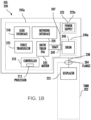
- FIG. 1B illustrates a block diagram of the ESG 200 shown in FIG. 1 , in accordance with an example embodiment.
- the ESG 200 can include three compartments, a drum compartment 240a, a drive compartment 225a, and a power supply compartment 222a.
- the drum compartment 240a can include the drum 240 on which a wire 238 can be wound.
- the drum 240 can be rotated in one direction by the drive compartment 245a to lower the displacer 235, and the drum 240 can be rotated in another direction by the drive compartment 245a to raise the displacer 235.
- the drum 240 can include any suitable structure for raising and lowering the displacer 235 via rotation.
- the drive compartment 245a can include a motor 245 comprising a drive train 246, which imparts rotation to the drum 240 via a shaft 249.
- the drive train 246 or shaft 249 could generate a magnetic field, and a magnetic coupling 247 can be used to convey torque between the shaft 249 and the drum 240.
- no direct connection may be needed between the drum compartment 240a and the other compartments 245a, 222a.
- other techniques for causing rotation of the drum 240 can be used, such as when the shaft 249 is physically connected to the drum 240.
- the drive train 246 includes any suitable structure for imparting rotation to the drum 240.
- the drive train 246 may include a stepper motor that causes the drum 240 to rotate in specified steps, meaning the drum 240 does not rotate freely but rotates in defined amounts or "steps.” Each step of the motor 245 should therefore impart a known amount of rotation to the drum 240.
- the drum 240 since the drum 240 may have a known diameter or circumference, the length of connector the wire 238 that is dispensed or collected during a single step rotation can be known with a high degree of certainty.
- the drive compartment 245a also can include a force transducer 225 which can identify the torque induced on the drum 240 by the weight of the displacer 235. When the displacer 235 is dangling from the wire 238, the measured torque is higher. When the displacer 235 is completely or partially submerged in the material in the tank, the measured torque is lower.
- the force transducer 225 generally identifies the torque on the drum 240 by measuring the torque on the shaft 249.
- ESG 200 is shown including a user interface 218 and a network interface 220 in the drive compartment 245a.
- the user interface 218 facilitates communications between the ESG 200 and an operator or other plant personnel.
- the user interface 218 can provide data from an operator to the controller 210, such as a command to initiate level measurements, a command to raise or lower the displacer 235, or a command to enable or disable testing of the ESG 200.
- the user interface 218 can also allow the personnel to review measurement data generated by the ESG 200.
- the user interface 218 can include any suitable interface for interacting with one or more users, such as a keypad or keyboard and a display.
- the network interface 220 can facilitate the communication of data to or from the ESG 200.
- the network interface 220 could receive level measurements calculated by ESG 200 and transmit the level measurements to one or more external destinations (such as the force transducer 225).
- the network interface 220 can include any suitable structure supporting wired or wireless communications, such as an Ethernet interface, an RF transceiver, or other wired or wireless interface.
- the power supply compartment 222a includes a power supply 222, which provides operating power for the ESG 200.
- the power supply 222 can provide power to various components of the drive compartment245a. Depending on the implementation, the power supply 222 may or may not supply power to the drum compartment 240a.
- the power supply 222 can include any suitable structure for providing power, such as a battery, fuel cell, or solar cell.
- the servo or ESG 200 shown in FIG. 1A and FIG. 1B is presented herein for illustrative and exemplary purposes only and should not be considered a limiting feature of the embodiments.
- Other types of devices and systems may be utilized in place of the ESG 200 to achieve the same results of the embodiments.
- the non-limiting SmartServo FlexLine 954 device may be adapted for use with the embodiments.
- the SmartServo FlexLine 954 device is described and illustrated in the document entitled "Installation Manual 954 SmartServo FlexLine," Part No: 4417341 Revision 10, 2019, Honeywell International Inc., which is incorporated herein by reference in its entirety.
- FIG. 2 illustrates a block diagram of a density measurement system 302 that includes the ESG 200 and one or more pressure sensors 300 in accordance with an embodiment.
- the ESG 200 can be used for accurate measurement of product level and the water interface level in the tank 202 (e.g., a bulk storage tank used for typical hydrocarbons (often referred to as fuel and oil) and a variety of other liquid chemicals).
- These products can range from very light chemicals, like so called LPG's (mixtures of propane and butane or even liquefied natural gas (LNG)) to all types of refined products such as naphtha, gasoline, diesel, jet fuels, lubricants and all types of chemicals, both pure and mixed.
- LPG's mixture of propane and butane or even liquefied natural gas (LNG)
- FIG. 3 illustrates a block diagram of a density measurement system 304 that can include an ESG 200, along with one or more pressure sensors 300 and/or one or more other types of sensors 301 (e.g., density sensor), in accordance with an embodiment.
- the density measurement system 304 includes the tank 202.
- the one or more pressure sensors 300 can be utilized to measure, for example, hydrostatic pressure in the tank 202.
- pressure sensor(s) 300 in some embodiments may comprise a pressure transducer.
- the sensor(s) 301 may be implemented as other types of sensors.
- sensor 301 may be implemented as an external (e.g., non-buoyancy based) density sensor that can be used compensate for errors.
- the use of a density sensor may result in a simpler approach than using a pressure sensor(s) and the "flow" (e.g., see method 100 of FIG. 4 ) would be even simpler.
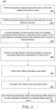
- FIG. 4 illustrates a flow chart of operations depicting logical operational steps of a density measurement method 100, which can be implemented in accordance with an embodiment.
- the density measurement method 100 can include the use of an installed sensor (e.g., ESG 200, pressure sensor(s) 300, other sensors 301 (e.g., density sensor), etc.), which can contribute to improved accuracy in measuring the product density in the storage tank 202. To achieve this, the accuracy in the individual densities should be improved. To do so, the measured average density from the installed sensor can be combined with the individual densities measured from a current instrument at several positions in the liquid storage tank 202.
- ESG 200 e.g., ESG 200, pressure sensor(s) 300, other sensors 301 (e.g., density sensor), etc.
- Density measurements in the storage tank 202 based on the previously discussed buoyancy principle have a significant advantage in that it is very easy to perform measurements at different locations in the storage tank 202, so that a density profile can be created. This way it is possible to create a very exact profile of different density layers in the product.
- various factors in the practical implementation of density measurement based on buoyancy may cause an offset error which cannot be easily removed.
- the offset error can be removed.
- a step or operation can be implemented in which one or more buoyancy measurements are made with respect to the product in the tank 202.
- pressure sensor measurements can be made in the tank 202 using, for example, the pressure sensor(s) 300 shown in FIG. 2 and FIG. 3 .
- the measurements made by the pressure sensor(s) 300 as shown at block 103 can result in pressure transmitter data.
- a step or operation can be performed to provide an indication of which product level the average calculated density based on pressure transmitter data input is more exact than the average density data from the buoyancy measurement(s) made as shown at block 102.
- any average density calculation based on the pressure transmitter data measured or determined when the product level is higher can be used to compensate for offset errors. That is, the higher the product level (e.g., liquid in a storage tank), the more exact the calculation of the offset error.
- the operation shown at block 106 can involve an average density calculation based on the pressure transmitter data collected from the pressure sensor(s) 300 and compensating for offset errors.
- the average calculated density at the highest product level can be used to calculate the offset of the buoyancy measurement. Even if the product level becomes very low, the calculated offset can still be used.
- a new offset can be calculated for diagnostic purposes.
- This new offset can be compared, as shown at block 110, to the last calculated offset and then used for continuous readjusting of a servo density offset value, or as an auto-calibration mechanism of a density offset value of the servo 200, as shown at block 112.
- a separate density sensor (e.g., other sensors 301 shown in FIG. 3 ) can be mounted in the tank wall of the tank 202 at a position about 1 meter from the bottom of the tank 202. If the displacer 235 is at the same height as the density sensor, the density sensor can be used to compensate offset errors in the density measurements based on the buoyancy measurement principle.
- At least some of the operations for the method(s) described herein can be implemented using software instructions stored on a computer useable storage medium for execution by a computer.
- a computer program product includes a computer useable storage medium to store a computer readable program.
- the computer-useable or computer-readable storage medium can be an electronic, magnetic, optical, electromagnetic, infrared, or semiconductor system (or apparatus or device).
- Examples of non-transitory computer-useable and computer-readable storage media include a semiconductor or solid-state memory, magnetic tape, a removable computer diskette, a random access memory (RAM), a read-only memory (ROM), a rigid magnetic disk, and an optical disk.
- Current examples of optical disks include a compact disk with read only memory (CD-ROM), a compact disk with read/write (CD-R/W), a digital video disk (DVD), Flash memory, and so on.
- embodiments of the invention may be implemented in hardware or in an implementation containing hardware and software elements.
- the software may include firmware, resident software, microcode, etc.
- the functions noted in the blocks may occur out of the order noted in the figures.
- two blocks shown in succession may, in fact, be executed concurrently, or the blocks may sometimes be executed in the reverse order, depending upon the functionality involved.
- the blocks of the block diagrams and/or flowchart illustration, and combinations of blocks in the block diagrams and/or flowchart illustration can be implemented by special purpose hardware-based systems that perform the specified functions or acts or carry out combinations of special purpose hardware and computer instructions.
Landscapes
- Physics & Mathematics (AREA)
- Health & Medical Sciences (AREA)
- Life Sciences & Earth Sciences (AREA)
- Chemical & Material Sciences (AREA)
- Analytical Chemistry (AREA)
- Biochemistry (AREA)
- General Health & Medical Sciences (AREA)
- General Physics & Mathematics (AREA)
- Immunology (AREA)
- Pathology (AREA)
- Measurement Of Levels Of Liquids Or Fluent Solid Materials (AREA)
- Measuring Fluid Pressure (AREA)
Applications Claiming Priority (1)
| Application Number | Priority Date | Filing Date | Title |
|---|---|---|---|
| US18/222,435 US20250020562A1 (en) | 2023-07-15 | 2023-07-15 | Improving accuracy by adding additional sensors to a density measuring system |
Publications (1)
| Publication Number | Publication Date |
|---|---|
| EP4495575A1 true EP4495575A1 (fr) | 2025-01-22 |
Family
ID=91620413
Family Applications (1)
| Application Number | Title | Priority Date | Filing Date |
|---|---|---|---|
| EP24183383.9A Pending EP4495575A1 (fr) | 2023-07-15 | 2024-06-20 | Amélioration de la précision par ajout de capteurs supplémentaires à un système de mesure de densité |
Country Status (3)
| Country | Link |
|---|---|
| US (1) | US20250020562A1 (fr) |
| EP (1) | EP4495575A1 (fr) |
| CN (1) | CN119321993A (fr) |
Citations (3)
| Publication number | Priority date | Publication date | Assignee | Title |
|---|---|---|---|---|
| CN106767936A (zh) * | 2017-02-09 | 2017-05-31 | 宣向斌 | 一种采用融合技术的浓度检测系统及其检测方法 |
| CN107271324A (zh) * | 2017-07-28 | 2017-10-20 | 国网山东省电力公司电力科学研究院 | 一种微量挥发性液体密度测量装置及方法 |
| EP2986964B1 (fr) * | 2013-04-18 | 2019-11-06 | Micro Motion, Inc. | Appareil et procédés pour la vérification d'un capteur d'un dispositif de mesure vibratoire |
-
2023
- 2023-07-15 US US18/222,435 patent/US20250020562A1/en active Pending
-
2024
- 2024-06-12 CN CN202410750610.7A patent/CN119321993A/zh active Pending
- 2024-06-20 EP EP24183383.9A patent/EP4495575A1/fr active Pending
Patent Citations (3)
| Publication number | Priority date | Publication date | Assignee | Title |
|---|---|---|---|---|
| EP2986964B1 (fr) * | 2013-04-18 | 2019-11-06 | Micro Motion, Inc. | Appareil et procédés pour la vérification d'un capteur d'un dispositif de mesure vibratoire |
| CN106767936A (zh) * | 2017-02-09 | 2017-05-31 | 宣向斌 | 一种采用融合技术的浓度检测系统及其检测方法 |
| CN107271324A (zh) * | 2017-07-28 | 2017-10-20 | 国网山东省电力公司电力科学研究院 | 一种微量挥发性液体密度测量装置及方法 |
Also Published As
| Publication number | Publication date |
|---|---|
| CN119321993A (zh) | 2025-01-17 |
| US20250020562A1 (en) | 2025-01-16 |
Similar Documents
| Publication | Publication Date | Title |
|---|---|---|
| US4852054A (en) | Volumetric leak detection system for underground storage tanks and the like | |
| EP3359926B1 (fr) | Compensation de densité pour jauges électromécaniques de niveau de liquide | |
| JPH0612284B2 (ja) | 静電容量流体レベル・センサの校正方法及び校正器 | |
| BR112012003541A2 (pt) | sistema e método para a detecção de vazamentos | |
| JPS62223640A (ja) | 液体貯蔵タンクにおける漏洩検出のためのシステム | |
| CN103998904A (zh) | 估算以低温贮存的多相流体的体积和质量的装置和方法 | |
| CN102288256A (zh) | 一种密闭容器液位测量系统 | |
| CA1196802A (fr) | Methode et instrument de mesure de pressions, notament celles des fluides | |
| US20070006646A1 (en) | Apparatus for measuring and indicating the level and/or volume of a liquid stored in a container | |
| US4262531A (en) | Fluid-gauging methods and systems | |
| EP4495575A1 (fr) | Amélioration de la précision par ajout de capteurs supplémentaires à un système de mesure de densité | |
| EP3290876B1 (fr) | Appareil et procédé de compensation de longueur de fil dans une jauge d'asservissement | |
| CN102252730B (zh) | 软体罐液位测量仪及其测量方法 | |
| EP3504521B1 (fr) | Mesure de frottement pour jauges électromécaniques de niveau de liquide | |
| Vennix | Low temperature volumetric properties and the development of an equation of state for methane | |
| RU2285908C1 (ru) | Устройство для измерения уровня и плотности жидкости (варианты) | |
| CN116337178B (zh) | 一种原油储罐内界面检测方法及检测装置 | |
| EP4459240A1 (fr) | Transfert d'énergie d'un tambour à un élément de déplacement | |
| CN116182993A (zh) | 储罐液位计算方法、装置、电子设备及机器可读存储介质 | |
| US20180306634A1 (en) | Automatic hysteresis correction for electromechanical level gauges | |
| US2593473A (en) | Electrically operated liquid level indicator | |
| RU2057300C1 (ru) | Способ определения массы нефтепродукта в резервуаре | |
| US20260104145A1 (en) | Automated determination of sampling and temperature measurement points of hydrocarbon liquid in a storage tank | |
| US3613436A (en) | Non-destructive testing of pressure vessels | |
| Sukhinets et al. | Intelligent System for Measuring the Level and Mass of Liquid in Fuel Reservoirs and Tanks During Pitching and Tilting |
Legal Events
| Date | Code | Title | Description |
|---|---|---|---|
| PUAI | Public reference made under article 153(3) epc to a published international application that has entered the european phase |
Free format text: ORIGINAL CODE: 0009012 |
|
| STAA | Information on the status of an ep patent application or granted ep patent |
Free format text: STATUS: REQUEST FOR EXAMINATION WAS MADE |
|
| 17P | Request for examination filed |
Effective date: 20240620 |
|
| AK | Designated contracting states |
Kind code of ref document: A1 Designated state(s): AL AT BE BG CH CY CZ DE DK EE ES FI FR GB GR HR HU IE IS IT LI LT LU LV MC ME MK MT NL NO PL PT RO RS SE SI SK SM TR |