EP4495956A1 - Ensemble de transmission d'énergie électrique et véhicule - Google Patents
Ensemble de transmission d'énergie électrique et véhicule Download PDFInfo
- Publication number
- EP4495956A1 EP4495956A1 EP23769781.8A EP23769781A EP4495956A1 EP 4495956 A1 EP4495956 A1 EP 4495956A1 EP 23769781 A EP23769781 A EP 23769781A EP 4495956 A1 EP4495956 A1 EP 4495956A1
- Authority
- EP
- European Patent Office
- Prior art keywords
- shape
- copper
- aluminum
- transmission assembly
- energy transmission
- Prior art date
- Legal status (The legal status is an assumption and is not a legal conclusion. Google has not performed a legal analysis and makes no representation as to the accuracy of the status listed.)
- Pending
Links
Images
Classifications
-
- H—ELECTRICITY
- H01—ELECTRIC ELEMENTS
- H01B—CABLES; CONDUCTORS; INSULATORS; SELECTION OF MATERIALS FOR THEIR CONDUCTIVE, INSULATING OR DIELECTRIC PROPERTIES
- H01B7/00—Insulated conductors or cables characterised by their form
- H01B7/0009—Details relating to the conductive cores
-
- H—ELECTRICITY
- H01—ELECTRIC ELEMENTS
- H01B—CABLES; CONDUCTORS; INSULATORS; SELECTION OF MATERIALS FOR THEIR CONDUCTIVE, INSULATING OR DIELECTRIC PROPERTIES
- H01B1/00—Conductors or conductive bodies characterised by the conductive materials; Selection of materials as conductors
- H01B1/02—Conductors or conductive bodies characterised by the conductive materials; Selection of materials as conductors mainly consisting of metals or alloys
-
- H—ELECTRICITY
- H01—ELECTRIC ELEMENTS
- H01B—CABLES; CONDUCTORS; INSULATORS; SELECTION OF MATERIALS FOR THEIR CONDUCTIVE, INSULATING OR DIELECTRIC PROPERTIES
- H01B1/00—Conductors or conductive bodies characterised by the conductive materials; Selection of materials as conductors
- H01B1/02—Conductors or conductive bodies characterised by the conductive materials; Selection of materials as conductors mainly consisting of metals or alloys
- H01B1/023—Alloys based on aluminium
-
- H—ELECTRICITY
- H01—ELECTRIC ELEMENTS
- H01B—CABLES; CONDUCTORS; INSULATORS; SELECTION OF MATERIALS FOR THEIR CONDUCTIVE, INSULATING OR DIELECTRIC PROPERTIES
- H01B1/00—Conductors or conductive bodies characterised by the conductive materials; Selection of materials as conductors
- H01B1/02—Conductors or conductive bodies characterised by the conductive materials; Selection of materials as conductors mainly consisting of metals or alloys
- H01B1/026—Alloys based on copper
-
- H—ELECTRICITY
- H01—ELECTRIC ELEMENTS
- H01B—CABLES; CONDUCTORS; INSULATORS; SELECTION OF MATERIALS FOR THEIR CONDUCTIVE, INSULATING OR DIELECTRIC PROPERTIES
- H01B7/00—Insulated conductors or cables characterised by their form
- H01B7/17—Protection against damage caused by external factors, e.g. sheaths or armouring
- H01B7/18—Protection against damage caused by wear, mechanical force or pressure; Sheaths; Armouring
- H01B7/22—Metal wires or tapes, e.g. made of steel
- H01B7/221—Longitudinally placed metal wires or tapes
- H01B7/223—Longitudinally placed metal wires or tapes forming part of a high tensile strength core
-
- H—ELECTRICITY
- H01—ELECTRIC ELEMENTS
- H01B—CABLES; CONDUCTORS; INSULATORS; SELECTION OF MATERIALS FOR THEIR CONDUCTIVE, INSULATING OR DIELECTRIC PROPERTIES
- H01B7/00—Insulated conductors or cables characterised by their form
- H01B7/17—Protection against damage caused by external factors, e.g. sheaths or armouring
- H01B7/28—Protection against damage caused by moisture, corrosion, chemical attack or weather
- H01B7/2806—Protection against damage caused by corrosion
-
- H—ELECTRICITY
- H01—ELECTRIC ELEMENTS
- H01B—CABLES; CONDUCTORS; INSULATORS; SELECTION OF MATERIALS FOR THEIR CONDUCTIVE, INSULATING OR DIELECTRIC PROPERTIES
- H01B7/00—Insulated conductors or cables characterised by their form
- H01B7/42—Insulated conductors or cables characterised by their form with arrangements for heat dissipation or conduction
- H01B7/421—Insulated conductors or cables characterised by their form with arrangements for heat dissipation or conduction for heat dissipation
- H01B7/426—Insulated conductors or cables characterised by their form with arrangements for heat dissipation or conduction for heat dissipation using cooling fins, ribs
-
- H—ELECTRICITY
- H01—ELECTRIC ELEMENTS
- H01R—ELECTRICALLY-CONDUCTIVE CONNECTIONS; STRUCTURAL ASSOCIATIONS OF A PLURALITY OF MUTUALLY-INSULATED ELECTRICAL CONNECTING ELEMENTS; COUPLING DEVICES; CURRENT COLLECTORS
- H01R31/00—Coupling parts supported only by co-operation with counterpart
- H01R31/06—Intermediate parts for linking two coupling parts, e.g. adapter
-
- H—ELECTRICITY
- H01—ELECTRIC ELEMENTS
- H01R—ELECTRICALLY-CONDUCTIVE CONNECTIONS; STRUCTURAL ASSOCIATIONS OF A PLURALITY OF MUTUALLY-INSULATED ELECTRICAL CONNECTING ELEMENTS; COUPLING DEVICES; CURRENT COLLECTORS
- H01R4/00—Electrically-conductive connections between two or more conductive members in direct contact, i.e. touching one another; Means for effecting or maintaining such contact; Electrically-conductive connections having two or more spaced connecting locations for conductors and using contact members penetrating insulation
- H01R4/10—Electrically-conductive connections between two or more conductive members in direct contact, i.e. touching one another; Means for effecting or maintaining such contact; Electrically-conductive connections having two or more spaced connecting locations for conductors and using contact members penetrating insulation effected solely by twisting, wrapping, bending, crimping, or other permanent deformation
- H01R4/18—Electrically-conductive connections between two or more conductive members in direct contact, i.e. touching one another; Means for effecting or maintaining such contact; Electrically-conductive connections having two or more spaced connecting locations for conductors and using contact members penetrating insulation effected solely by twisting, wrapping, bending, crimping, or other permanent deformation by crimping
-
- H—ELECTRICITY
- H01—ELECTRIC ELEMENTS
- H01R—ELECTRICALLY-CONDUCTIVE CONNECTIONS; STRUCTURAL ASSOCIATIONS OF A PLURALITY OF MUTUALLY-INSULATED ELECTRICAL CONNECTING ELEMENTS; COUPLING DEVICES; CURRENT COLLECTORS
- H01R4/00—Electrically-conductive connections between two or more conductive members in direct contact, i.e. touching one another; Means for effecting or maintaining such contact; Electrically-conductive connections having two or more spaced connecting locations for conductors and using contact members penetrating insulation
- H01R4/58—Electrically-conductive connections between two or more conductive members in direct contact, i.e. touching one another; Means for effecting or maintaining such contact; Electrically-conductive connections having two or more spaced connecting locations for conductors and using contact members penetrating insulation characterised by the form or material of the contacting members
- H01R4/62—Connections between conductors of different materials; Connections between or with aluminium or steel-core aluminium conductors
-
- H—ELECTRICITY
- H01—ELECTRIC ELEMENTS
- H01R—ELECTRICALLY-CONDUCTIVE CONNECTIONS; STRUCTURAL ASSOCIATIONS OF A PLURALITY OF MUTUALLY-INSULATED ELECTRICAL CONNECTING ELEMENTS; COUPLING DEVICES; CURRENT COLLECTORS
- H01R4/00—Electrically-conductive connections between two or more conductive members in direct contact, i.e. touching one another; Means for effecting or maintaining such contact; Electrically-conductive connections having two or more spaced connecting locations for conductors and using contact members penetrating insulation
- H01R4/58—Electrically-conductive connections between two or more conductive members in direct contact, i.e. touching one another; Means for effecting or maintaining such contact; Electrically-conductive connections having two or more spaced connecting locations for conductors and using contact members penetrating insulation characterised by the form or material of the contacting members
- H01R4/62—Connections between conductors of different materials; Connections between or with aluminium or steel-core aluminium conductors
- H01R4/625—Soldered or welded connections
-
- B—PERFORMING OPERATIONS; TRANSPORTING
- B60—VEHICLES IN GENERAL
- B60L—PROPULSION OF ELECTRICALLY-PROPELLED VEHICLES; SUPPLYING ELECTRIC POWER FOR AUXILIARY EQUIPMENT OF ELECTRICALLY-PROPELLED VEHICLES; ELECTRODYNAMIC BRAKE SYSTEMS FOR VEHICLES IN GENERAL; MAGNETIC SUSPENSION OR LEVITATION FOR VEHICLES; MONITORING OPERATING VARIABLES OF ELECTRICALLY-PROPELLED VEHICLES; ELECTRIC SAFETY DEVICES FOR ELECTRICALLY-PROPELLED VEHICLES
- B60L53/00—Methods of charging batteries, specially adapted for electric vehicles; Charging stations or on-board charging equipment therefor; Exchange of energy storage elements in electric vehicles
- B60L53/10—Methods of charging batteries, specially adapted for electric vehicles; Charging stations or on-board charging equipment therefor; Exchange of energy storage elements in electric vehicles characterised by the energy transfer between the charging station and the vehicle
- B60L53/14—Conductive energy transfer
- B60L53/16—Connectors, e.g. plugs or sockets, specially adapted for charging electric vehicles
-
- B—PERFORMING OPERATIONS; TRANSPORTING
- B60—VEHICLES IN GENERAL
- B60L—PROPULSION OF ELECTRICALLY-PROPELLED VEHICLES; SUPPLYING ELECTRIC POWER FOR AUXILIARY EQUIPMENT OF ELECTRICALLY-PROPELLED VEHICLES; ELECTRODYNAMIC BRAKE SYSTEMS FOR VEHICLES IN GENERAL; MAGNETIC SUSPENSION OR LEVITATION FOR VEHICLES; MONITORING OPERATING VARIABLES OF ELECTRICALLY-PROPELLED VEHICLES; ELECTRIC SAFETY DEVICES FOR ELECTRICALLY-PROPELLED VEHICLES
- B60L53/00—Methods of charging batteries, specially adapted for electric vehicles; Charging stations or on-board charging equipment therefor; Exchange of energy storage elements in electric vehicles
- B60L53/10—Methods of charging batteries, specially adapted for electric vehicles; Charging stations or on-board charging equipment therefor; Exchange of energy storage elements in electric vehicles characterised by the energy transfer between the charging station and the vehicle
- B60L53/14—Conductive energy transfer
- B60L53/18—Cables specially adapted for charging electric vehicles
-
- H—ELECTRICITY
- H01—ELECTRIC ELEMENTS
- H01R—ELECTRICALLY-CONDUCTIVE CONNECTIONS; STRUCTURAL ASSOCIATIONS OF A PLURALITY OF MUTUALLY-INSULATED ELECTRICAL CONNECTING ELEMENTS; COUPLING DEVICES; CURRENT COLLECTORS
- H01R2201/00—Connectors or connections adapted for particular applications
- H01R2201/26—Connectors or connections adapted for particular applications for vehicles
Definitions
- the present disclosure relates to the technical field of electric energy transmission, and particular to an electric energy transmission assembly and a vehicle.
- electric automobiles are vehicles that are powered by a vehicle-mounted power supply and of which wheels are driven by a motor.
- the electric automobiles are widely accepted and marketed by people for environmental protection and energy saving.
- the driving range of electric automobiles has been greatly increased and the charging time has been greatly shortened.
- Electric automobiles have entered a new stage of development and start to step into the practical use stage.
- the significant reduction in the charging time is accompanied by the popularization of high-power automobile charging.
- the diameter of the high-voltage cables used for high-power automobile charging becomes larger and larger.
- High-voltage wiring is mainly used in the industry of new energy electric automobiles and the related product fields thereof.
- connection cables and terminals between the connectors and the charging socket are copper structures or multi-core aluminum wire structures.
- the price of pure copper or copper alloy materials is high, which undoubtedly increases the cost of the electric automobiles. Copper is the most ideal conductor for cables. However, the copper is expensive and price variable, and most importantly, there is a shortage of copper resources.
- aluminum Compared with copper, aluminum has slightly poorer hardness, plasticity and corrosion resistance, but it is lighter in weight and second only to copper in electric conductivity, so aluminum can partially replace copper in the field of electric connection.
- electrochemical corrosion will occur between copper and aluminum after they are directly connected.
- Aluminum is susceptible to corrosion to cause an increased resistance in the connection area, which is prone to serious consequences in electrical connection, such as function failures, fire disasters, etc.
- the present disclosure proposes a new technical solution.
- an electric energy transmission assembly which includes at least one electric connection skeleton and connectors arranged at two ends of the electric connection skeleton.
- the connector includes a connection terminal, the two ends of the electric connection skeleton are electrically connected with the connection terminals, at least a part of the electric connection skeleton is a rigid conductor, and a material of the rigid conductor includes a copper-aluminum composite material.
- a cross section of the electric connection skeleton is one or more selected from a circular shape, an oval shape, a rectangular shape, a polygonal shape, an A shape, a B shape, a D shape, an M shape, an N shape, an O shape, an S shape, an E shape, an F shape, an H shape, a K shape, an L shape, a T shape, a P shape, a U shape, a V shape, a W shape, an X shape, a Y shape, a Z shape, a semi-arc shape, an arc shape, and a wavy shape.
- a tensile strength of a rigid portion of the electric connection skeleton is higher than 75MPa.
- connection terminals are copper or a copper alloy, and the electric connection skeleton is connected with the connection terminal in a welding or crimping manner.
- the electric connection skeleton is composed of an aluminum wire core and a copper layer covering the aluminum wire core.
- a material of the aluminum wire core is pure aluminum or an aluminum alloy with an aluminum content of 89% or more.
- a junction of the copper layer and the aluminum wire core contains a copper-aluminum transition layer formed by copper atoms and aluminum atoms penetrating into or combining with each other.
- the copper-aluminum transition layer includes at least 39wt% of a copper-aluminum mixture.
- a copper-aluminum crystalline solid solution layer in which copper atoms and aluminum atoms penetrate into each other is formed between the aluminum wire core and the copper layer.
- a mass percent of copper element in the copper-aluminum crystalline solid solution layer is 5% to 93%.
- a radial size of the aluminum wire core is in direct proportion to a radial size of the copper layer.
- a sectional area of the copper layer at least accounts for 3% of a sectional area of the electric connection skeleton.
- the aluminum wire core is a hollow structure.
- the electric connection skeleton is provided with at least one heat dissipation fin along a radial direction.
- the heat dissipation fin is integrally formed with the copper-aluminum composite material.
- a cross section of the heat dissipation fin is one or more selected from a gear shape, a trapezoidal shape, a polygonal shape, a quadrilateral shape, a prismatic shape, a curve shape, and a wavy shape.
- thermoelectric layer There is a plurality of heat dissipation fins, and the plurality of heat dissipation fins are distributed on a periphery of the copper layer.
- the plurality of heat dissipation fins is evenly distributed on the periphery of the copper layer.
- a maximum radial height of the heat dissipation fins is 50% to 260% of a maximum radial thickness of the copper layer.
- the heat dissipation fin is arranged in a spiral shape in an axial direction of the copper layer.
- a minimum screw pitch of the spiral shape is a maximum outer diameter of the electric connection skeleton.
- At least two said spirals are alternatively arranged in the axial direction of the copper layer.
- An insulating layer is provided and sleeved on the periphery of the copper layer.
- An insulating layer is provided and sleeved on an outer periphery of the dissipation fin.
- a shielding layer and an outer insulating layer are further provided and sleeved on a periphery of the insulating layer.
- the connector includes an inner shell having a shielding effect, and the shielding layer is electrically connected with the inner shell.
- a material of the inner shell is a conductive metal or conductive polymer material.
- One of the connectors is a charging socket.
- Another aspect of the present disclosure provides a vehicle, includes an electric energy transmission assembly as described above.
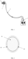
- An electric energy transmission assembly includes at least one electric connection skeleton 3 and connectors 1 provided at two ends of the electric connection skeleton 3.
- the connector 1 includes a connection terminal 2, the two ends of the electric connection skeleton 3 are electrically connected with the connection terminals 2, at least a part of the electric connection skeleton 3 is a rigid conductor, and the material of the rigid conductor includes a copper-aluminum composite material.
- an insulating layer 5 (not shown in the figures) is provided and sleeved on the periphery of the copper layer 32.
- an insulating layer 5 is provided sleeved on the periphery of the heat dissipation fins 4.
- the material of the insulating layer 5 is PVC (Polyvinyl chloride), which on the one hand guarantees the insulation performance and on the other hand has water resistance, wear resistance and hardness.
- the insulating material for cables may also be one or more selected from rubber, TPE (Thermoplastic Elastomers), XPE, PP (Polypropylene), XLPE (Crosslinked Polyethylene), FEP (Fluorinated Ethylene Propylene), ETFE (Ethylene-Tetra-Fluoro-Ethlene), TPR (Thermo-Plastic-Rubber), and TPFE (Polytetrafluoroethylene).
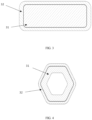
- the cross section of the electric connection skeleton 3 is one or more selected from a circular shape, an oval shape, a rectangular shape, a polygonal shape, an E shape, an F shape, an H shape, a K shape, an L shape, a T shape, a P shape, a U shape, a V shape, a W shape, an X shape, a Y shape, a Z shape, a semi-arc shape, an arc shape, and a wavy shape.
- the cross section of the electric connection skeleton 3 is circular, rectangular and hexagonal, which allow for better wiring according to the outline of the body of the electric vehicle to reduce the consumables for wiring.
- the tensile strength of the rigid portion of the electric connection skeleton 3 is higher than 75MPa.
- a rigid body refers to an object whose shape and size do not change and within which the relative position of each point does not change during motion and after being acted upon by a force.
- An absolutely rigid body does not actually exist, but is only an ideal model, because any object would be more or less deformed after being acted upon by a force. If the degree of deformation is extremely small relative to the geometric size of the object itself, the deformation can be omitted in the study of the movement of the object. Thus, during use of the electric connection skeleton 3 made of a rigid body material, the amount of deformation produced is so small that it can be omitted, and the larger the tensile strength of the rigid body is, the smaller the amount of deformation is.
- a method for testing the tensile value of the electric connection skeleton 3 is as follows: A universal tensile test machine is used. The two ends of the electric connection skeleton 3 are respectively fixed to a tensile jigs of the universal tensile test machine and stretching at a speed of 50 mm/min is performed, and the tensile value when the electric connection skeleton 3 being pulled apart is recorded. In this embodiment, a tensile value greater than 1600N is a qualified value.
- a method for testing the torque of the electric connection skeleton 3 is as follows: A torque tester is used. Electric connection skeleton 3 are bent 90° at the same radius and the same speed, and the torque values of deformation of the electric connection skeletons 3 in the bending process are tested. In this embodiment, a torque value less than 60N•m is an exemplary value.
- the test method that the electric connection skeleton 3 samples with the same size and the same specification and with different tensile strengths and the connectors 1 with the same dimensions are selected, assembled together and fixed on a vibration test platform, and observe whether the electric connection skeletons 3 have abnormal sounds during the vibration test.
- Table 1 Influence of different tensile strengths on the torque value and abnormal sound of the electric connection skeleton 3 Different tensile strengths (MPa) 60 70 75 85 120 200 280 330 380 430 480 500 Tensile value of electric connection skeleton 3 when being pulled apart (N) 1422 1612 1688 1709 1759 1815 1856 1909 1950 1989 2040 2067 Torque value when bending in a horizontal direction (N•m) 6 8 9 18 27 34 44 46 49 52 59 70 Whether the electric connection skeleton 3 has abnormal sounds Yes Yes No No No No No No No No No No No No No No No No No No No No No No No No No No No No No No No No No No No No No No No No No No
- the inventor further exemplarily selects the tensile strength of the electric connection skeleton 3 to be higher than 75MPa and lower than or equal to 480MPa.
- connection terminals 2 The material of the connection terminals 2 is copper or a copper alloy, and the electric connection skeleton 3 is connected with the connection terminals 2 in a welding or crimping manner.
- connection terminals 2 and the electric connection skeleton 3 may be connected by welding.
- a copper-clad aluminum composite conductor has good weldability. Since a copper-clad aluminum has a layer of pure copper on its surface, it has the same weldability as a pure copper wire, and therefore can be better welded with the connection terminals 2.
- the specific welding method is one or more selected from a resistance welding, a friction welding, an ultrasonic welding, an arc welding, a laser welding, an electron beam welding, a pressure diffusion welding, and a magnetic induction welding.
- Resistance welding refers to a method of using a large current to pass through the contact point between an electrode and a workpiece and generating heat by the contact resistance to achieve welding.
- Friction welding refers to a method of using the heat generated by rubbing of the contact face of the workpieces as a heat source and enabling the workpiece to be subjected to plastic deformation under the action of pressure so as to perform welding.
- Ultrasonic welding is a method in which high-frequency vibration waves are transmitted to the surfaces of the two objects to be welded, and under pressurization, the surfaces of the two objects rub against each other to achieve a fusion between two molecular layers.
- Arc welding is a method in which an electric arc is used as a heat source, and the electric energy is converted into the heat and mechanical energy required by welding by using the physical phenomenon of air discharge, thereby achieving the purpose of connecting metals.
- the method mainly includes shielded metal arc welding, submerged arc welding, gas shielded welding, etc.
- Laser welding is an efficient and precise welding method that takes a laser beam with high energy density as a heat source.
- Electron beam welding is a method to achieve welding by bombarding the welding face placed in a vacuum or non-vacuum environment with an accelerated and focused electron beam to cause the workpieces to be welded to melt for welding.
- Pressure welding is a method of applying pressure to the workpiece to be welded to bring the connection faces into close contact to produce certain plastic deformation to complete the welding.
- Diffusion welding refers to a solid-state welding method in which the workpieces are subjected to the pressurization at high temperature without producing visible deformation and relative movement.
- Magnetic induction welding is a method in which the two workpieces to be welded produce an instantaneous high-speed collision under the action of a strong pulsed magnetic field, surface layers of materials are subjected to high pressure waves, and thus atoms of the two materials meet within the atomic spacing, thereby forming stable metallurgical bonding on an interface. It is one kind of solid-state cold welding, by which conducting metals with similar properties or dissimilar properties can be welded together.
- Crimping is a production process in which the electric connection skeleton 3 and the connection terminals 2 are assembled and stamped into a whole by using a crimping machine.
- the advantage of crimping lies in mass production, and the use of an automatic crimping machine makes it possible to quickly manufacture large number of products of stable quality.
- connection method or combination of connection methods is selected according to the actual state of the electric connection skeleton 3 and the connection terminals 2, so as to achieve effective electric connection.
- the electric connection skeleton 3 is composed of an aluminum wire core 31 and a copper layer 32 covering the aluminum wire core 31.
- a copper-clad aluminum cable replaces the current copper-core cable.
- the copper-clad aluminum conductor reduces the alternating current resistance.
- a current passing through the surface part of a single conductor per unit volume is greater than a current passing through the center part of the conductor per unit area.
- the current passing through its center part is smaller than that passing through its circumference part, so it is most reasonable and economical to make the center conductor and the circumference conductor with different metallic materials.
- the copper-clad aluminum composite conductor increases the total area of the conductor, and also increases the surface area of the conductor, so that the heat dissipation area of the conductor is increased and the heat dissipation condition of the cable is improved.
- the copper-clad aluminum composite conductor has good corrosion resistance. Aluminum is more susceptible to corrosion and oxidation than copper. In the copper-clad aluminum conductor, aluminum is completely covered and does not contact air and water, so the physical and chemical properties of the entire conductor are more stable.
- the copper-clad aluminum composite conductor has the characteristics of low cost and light weight. Compared with a copper-core cable having the same technical indexes, the copper-clad aluminum composite conductor cable can save more than 25% of the cost, and the weight of it is almost half of that of a pure copper wire.
- the copper-clad aluminum composite conductor has good weldability. Since the copper-clad aluminum wire has a layer of pure copper on its surface, it has the same weldability as a pure copper wire and can be conveniently installed and produced. In a word, the copper-clad aluminum composite conductor not only maintains the characteristics of high conductivity, reliable surface electrical contact, corrosion resistance, etc., but also has the advantages of small specific gravity, abundant resources, low price, etc. of aluminum, and it also has good flexibility and can be easily welded.
- the material of the aluminum wire core 31 is pure aluminum or an aluminum alloy with an aluminum content of 89% or more.
- Pure aluminum or an aluminum alloy with an aluminum content of 89% or more is used instead of the copper conductor core commonly used in the prior art.
- the density of aluminum is only one-third of copper.
- the wire diameter ratios of aluminum and copper are only 1.28 times, and the weight of an aluminum material is only half of that of a copper material with the same current carrying capacity. Therefore, the wire weight can be greatly reduced without increasing the cable loading space, which is conducive to the weight reduction of the vehicle.
- an aluminum conductor core comprising aluminum or its alloy material
- a copper conductor core that has large specific gravity and a high material price
- the aluminum alloy is an aluminum-copper alloy or an aluminum-magnesium alloy or an aluminum-lithium alloy or an aluminum-manganese alloy or an aluminum-zinc alloy or an aluminum-silicon alloy which contain an aluminum content of 89% or more.
- a junction of the copper layer 32 and the aluminum wire core 31 contains includes a copper-aluminum transition layer 33 formed by copper atoms and aluminum atoms penetrating into or combining with each other.
- the copper-aluminum transition layer 33 described in the present disclosure is a copper-aluminum transition layer 33 formed by copper atoms and aluminum atoms penetrating into or combining with each other under the action of pressure at the junction surface of the copper layer 32 and the aluminum layer, which not only avoids the occurrence of electrochemical corrosion between copper and aluminum, but also improves the electrical and mechanical properties of the copper-aluminum connection, so that the mechanical and electrical properties of the copper-aluminum composite substrate material are significantly improved.
- the copper-aluminum transition layer 33 includes at least 39wt% of a copper-aluminum mixture.
- the content of the other components in the copper-aluminum transition layer 33 is higher than or equal to 61wt%. If the proportion of copper pure element and aluminum pure element in the copper-aluminum transition layer 33 is large, it indicates that the copper-aluminum welding is not sufficient and the copper pure element and aluminum pure element are not fused into a copper-aluminum mixture.
- the proportion of a copper-aluminum compound in the copper-aluminum transition layer 33 is large, in which the copper-aluminum compound has very poor conductivity and high brittleness, the mechanical and electrical properties of the copper-aluminum composite substrate material would be reduced when the content of the copper-aluminum compound is high.
- the inventor carried out relevant tests. The inventor carried out drawing force tests and voltage drop tests for copper-aluminum transition layers 33 with different weight percent of copper-aluminum mixtures.
- the copper-aluminum transition layer 33 includes less than 39wt% of a copper-aluminum mixture, the drawing force of the electric connection skeleton 3 is less than 3000N, which is not qualified; at the same time, the voltage drop of the electric connection skeleton 3 is greater than 0.5mV, which cannot satisfy the requirement for the mechanical and electrical properties of the electric connection skeleton 3.
- the copper-aluminum transition layer 33 includes not less than 39wt% of a copper-aluminum mixture.
- a copper-aluminum crystalline solid solution layer in which copper atoms and aluminum atoms penetrate into each other is formed between the aluminum wire core and the copper layer.
- the copper-aluminum crystalline solid solution refers to an alloy phase in which the copper and aluminum solute atoms dissolve in the solvent lattices and the type of the solvent is still maintained.
- the crystal formed by copper as a matrix and aluminum atoms or molecules dissolved in the matrix can avoid the occurrence of electrochemical corrosion between copper and aluminum.
- the presence of the copper-aluminum crystalline solid solution layer improves the electrical and mechanical properties of copper-aluminum connection.
- the copper-aluminum crystalline solid solution layer contains copper element.
- the inventor carried out relevant tests. The inventor carried out voltage drop tests for copper-aluminum crystalline solid solution layers with different mass percent of copper element. If the voltage drop of the copper-aluminum solid solution is greater than 0.5mV, it is unqualified. The results are shown in Table 3.
- Table 3 Influence of different percent of copper element on the voltage drop of the copper-aluminum crystalline solid solution layer Mass fraction of copper element in the copper-aluminum crystalline solid solution layer (%) 3 5 8 10 20 35 50 65 80 90 93 95 Voltage drop of the copper-aluminum crystalline solid solution layer (mV) 0.52 0.49 0.45 0.42 0.38 0.33 0.29 0.34 0.39 0.45 0.48 0.53
- the radial size of the aluminum wire core 31 is in direct proportion to the radial size of the copper layer 32.
- the radial size of the aluminum wire core 31 and that of the copper layer 32 vary proportionally to ensure the connection strength.
- the sectional area of the copper layer 32 accounts for at least 3% of the sectional area of the electric connection skeleton 3.
- a current passing through the copper layer per unit surface area is greater than a current passing through the aluminum core per unit surface area. If the proportion of the sectional area of the copper layer 32 to the sectional area of the electric connection skeleton 3 is less than 3%, the resistance will increase and the use is affected.
- the aluminum wire core 31 is a hollow structure.
- the current passing through the surface part of a single conductor per unit volume is greater than the current passing through the center part of the conductor per unit area.
- the current passing through its center part is smaller than that passing through its circumference part, so the aluminum wire core 31 conductor at the center can be configured as a hollow structure.
- This practice can also reduce the weight of the electric connection skeleton 3, thus reducing the cost of the electric energy transmission assembly.
- the electric connection skeleton 3 is provided with at least one heat dissipation fin 4 along a radial direction.
- the provision of the heat dissipation fin 4 can increase the heat dissipation area of the electric connection skeleton 3 so as to improve the heat dissipation effect of the electric energy transmission assembly.
- the heat dissipation fin 4 is formed integrally with the copper-aluminum composite material.
- the heat dissipation fin 4 and the electric connection skeleton 3 is formed integrally using the same material, thereby improving the production efficiency.
- the cross section of the heat dissipation fin 4 is one or more selected from a gear shape, a trapezoidal shape, a polygonal shape, a quadrilateral shape, a prismatic shape, a curve shape, and a wavy shape.
- the cross section of the heat dissipation fin 4 is trapezoidal.
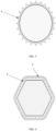
- FIGS. 5 to 6 there is a plurality of heat dissipation fins 4, and the plurality of heat dissipation fins 4 are distributed on the periphery of the copper layer 32.
- the plurality of heat dissipation fins 4 are evenly distributed on the periphery of the copper layer 32.
- the provision of the plurality of heat dissipation fins 4 on the periphery of the electric connection skeleton 3 not only increases the heat dissipation area to achieve better heat dissipation effect, but also ensures that all parts of the electric connection skeleton 3 are subjected to uniform force during the bending process of the electric connection skeleton 3 to ensure that the insulating layer 5 covering the electric connection skeleton 3 is subjected to uniform force.
- the maximum radial height of the heat dissipation fins 4 is 50% to 260% of the maximum radial thickness of the copper layer 32.
- the setting of the maximum radial height of the heat dissipation fins 4 has certain influence on the temperature rise of the electric connection skeleton 3.
- the test method is as follows. The same electric connection skeletons 3 are selected, the heat dissipation fins 4 are formed integrally with the electric connection skeletons 3, and the respective ratios of the radial height of the heat dissipation fins 4 to the maximum radial thickness of the copper layer 32 are different. In a sealed environment, the same current is passed through the different electric connection skeletons 3.
- a temperature rise less than 50K is a qualified value, and after the insulating layer 5 is peeled off, the electric connection skeletons 3 are bent 60° to observe whether the heat dissipation fins 4 are deformed.
- Table 4 Influence of the proportion of the maximum radial height of the heat dissipation fins 4 to the maximum radial thickness of the copper layer 32 on the temperature rise of the electric connection skeleton 3 and the deformation of the heat dissipation fin 4 The proportion of the maximum radial height of the heat dissipation fins 4 to the maximum outer diameter of the electric connection skeleton 3 (%) 10 20 50 80 100 130 140 160 180 200 260 280 300 Temperature rise of the electric connection skeleton 3 (K) 50.9 50.5 47.5 44 41.2 39.8 38.5 37.1 33.2 30.9 27.5 26.8 26.5 Whether the heat dissipation fins 4 are deformed No No No No No No No No No No No No No Yes Yes
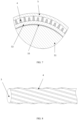
- the heat dissipation fin 4 is arranged in a spiral shape in an axial direction of the copper layer 32.
- the heat dissipation fin 4 is arranged in a spiral shape.
- a channel of spiral shape is formed between the heat dissipation fin 4 and the electric connection skeleton 3 and insulating layer 5.
- This design can ensure that the heat dissipation effect is the same at everywhere of the electric connection skeleton 3, and avoid local overheating.
- the radial height of the same one heat dissipation fin 4 is spirally arranged is the same, so that the gap between the insulating layer 5 and the electric connection skeleton 3 is also the same, which is more conductive to heat dissipation.
- the minimum screw pitch of the spiral shape is the maximum outer diameter of the electric connection skeleton 3.
- the minimum screw pitch of the spiral shape of the heat dissipation fins 4 is higher than or equal to the maximum outer diameter of the electric connection skeleton 3. If the screw pitch is too small, the gap between the heat dissipation arms is small and the heat dissipation effect is not achieved.
- At least two said spirals are alternatively arranged in the axial direction of the copper layer 32.
- the length of the helices is greater than the spirals being arranged in parallel, which increases the heat dissipation area, so that the heat dissipation effect of the electric energy transmission assembly is better.
- At least two spirals are arranged alternatively, which can increase the heat dissipation area of the electric connection skeleton 3.
- An insulating layer 5 is provided and sleeved on the periphery of the heat dissipation fins 4, and at least two heat dissipation arms are alternatively arranged to enable the insulating layer 5 to be subjected to a more uniform force.
- the heat dissipation fins 4 are arranged in a spiral shape.
- a channel of spiral shape is formed between the heat dissipation fins 4 and the electric connection skeleton 3 and insulating layer 5. This design can ensure that the heat dissipation effect is the same at everywhere of the electric connection skeleton 3, and avoid local overheating.
- the radial height of the same one heat dissipation fin 4 spirally arranged is the same, so that the gap between the insulating layer 5 and the electric connection skeleton 3 is also the same, which is more conductive to heat dissipation.
- the length of the heat dissipation fins 4 is greater than the heat dissipation fins 4 being arranged in parallel, which increases the heat dissipation area so that the heat dissipation effect of the electric energy transmission assembly is better.
- an insulating layer 5 is provided and sleeved on the periphery of the copper layer.
- the insulating layer 5 can prevent the electric connection skeleton 3 from contacting the vehicle shell and thus avoiding the short circuit phenomenon.
- an insulating layer is provided and sleeved on the periphery of the heat dissipation fins.
- the insulating layer can prevent the electric connection skeleton 3 from contacting the other parts inside the vehicle body and thus avoiding short circuit.
- the gap between the insulating layer 5 and the heat dissipation fins 4 forms a cavity.
- a heat dissipation device may be adopted to convey air to the cavity to form air circulation, thereby achieving a better heat dissipation effect.
- a shielding layer and an outer insulating layer are also provided and sleeved on the periphery of the insulating layer 5.
- the shielding layer can reduce the interference of the electromagnetic radiation generated by the electric connection skeleton 3 on the other electrical devices in the vehicle.
- the material of the shielding layer is a conductor, and it needs to be grounded. So, the insulating layer 5 is provided between the shielding layer and the electric connection skeleton 3 to prevent contact between the two.
- the outer insulating layer can prevent the shielding layer from contacting the vehicle shell and thus avoiding short circuit.
- the connector 1 includes an inner shell having a shielding effect, and the shielding layer is electrically connected with the inner shell.
- the material of the inner shell is a conductive metal or conductive polymer material.
- the shielding inner shell is electrically connected with the shielding layer to form a complete shielding device. It can play the role of a shielding layer to effectively shield the electromagnetic interference generated by the electrification of the electric connection skeleton 3, and therefore the use of a shielding net is saved, and the cost of the connector 1 assembly is reduced.
- one of the connectors 1 is a charging socket.
- One end of the electric connection skeleton 3 is connected to a terminal in the charging socket, and the other end can be connected to a vehicle-mounted battery to form a complete charging system.
- an electric vehicle including the above-described electric energy transmission assembly is provided.
Landscapes
- Engineering & Computer Science (AREA)
- Power Engineering (AREA)
- Transportation (AREA)
- Mechanical Engineering (AREA)
- Connections Effected By Soldering, Adhesion, Or Permanent Deformation (AREA)
- Body Structure For Vehicles (AREA)
Applications Claiming Priority (2)
| Application Number | Priority Date | Filing Date | Title |
|---|---|---|---|
| CN202210250033.6A CN114758818A (zh) | 2022-03-14 | 2022-03-14 | 一种电能传输总成及车辆 |
| PCT/CN2023/081361 WO2023174279A1 (fr) | 2022-03-14 | 2023-03-14 | Ensemble de transmission d'énergie électrique et véhicule |
Publications (2)
| Publication Number | Publication Date |
|---|---|
| EP4495956A1 true EP4495956A1 (fr) | 2025-01-22 |
| EP4495956A4 EP4495956A4 (fr) | 2025-07-16 |
Family
ID=82328228
Family Applications (1)
| Application Number | Title | Priority Date | Filing Date |
|---|---|---|---|
| EP23769781.8A Pending EP4495956A4 (fr) | 2022-03-14 | 2023-03-14 | Ensemble de transmission d'énergie électrique et véhicule |
Country Status (5)
| Country | Link |
|---|---|
| US (1) | US20250201440A1 (fr) |
| EP (1) | EP4495956A4 (fr) |
| CN (1) | CN114758818A (fr) |
| MX (1) | MX2024011362A (fr) |
| WO (1) | WO2023174279A1 (fr) |
Families Citing this family (2)
| Publication number | Priority date | Publication date | Assignee | Title |
|---|---|---|---|---|
| CN114758818A (zh) * | 2022-03-14 | 2022-07-15 | 吉林省中赢高科技有限公司 | 一种电能传输总成及车辆 |
| CN119069162B (zh) * | 2024-09-11 | 2025-02-14 | 广东日昭电工有限公司 | 一种抗短路耐热节能母线 |
Family Cites Families (15)
| Publication number | Priority date | Publication date | Assignee | Title |
|---|---|---|---|---|
| CN2914261Y (zh) * | 2006-06-20 | 2007-06-20 | 宋玉春 | 汽车用电缆 |
| KR20120126784A (ko) * | 2011-05-12 | 2012-11-21 | 이시영 | 방열판부 발열전선 |
| KR101914790B1 (ko) * | 2012-03-08 | 2018-11-02 | 엘에스전선 주식회사 | 동복 알루미늄 선재, 이를 포함하는 압축도체와 케이블 및 압축도체의 제조방법 |
| EP3046694B1 (fr) * | 2013-09-21 | 2019-11-06 | Applied Composite Material LLC | Composite d'aluminium recouvert de cuivre traité de manière isotherme et procédé et système de fabrication correspondants |
| CN204834134U (zh) * | 2015-08-18 | 2015-12-02 | 南京上科机电工业有限公司 | 一种防老化散热型通信电缆 |
| CN205564354U (zh) * | 2016-04-11 | 2016-09-07 | 河南省龙祥电力电缆有限公司 | 一种新能源汽车电源连接线 |
| CN106229058A (zh) * | 2016-07-26 | 2016-12-14 | 汉舟四川铜铝复合科技有限公司 | 一种强导电耐温升铜铝界面合金复合管母线 |
| CN106229034A (zh) * | 2016-08-23 | 2016-12-14 | 汉舟四川铜铝复合科技有限公司 | 一种抗折弯的高强度铜铝界面合金复合母线 |
| CN106653163B (zh) * | 2016-11-22 | 2018-08-24 | 吉林省中赢高科技有限公司 | 一种异形电缆及其制备方法 |
| CN106601324B (zh) * | 2016-12-07 | 2017-12-08 | 烟台孚信达双金属股份有限公司 | 一种高结合强度铜铝复合导电材料及其制备方法 |
| CN108199162B (zh) * | 2017-12-22 | 2024-01-26 | 深圳市沃尔新能源电气科技股份有限公司 | 液冷充电插座 |
| CN208589273U (zh) * | 2017-12-29 | 2019-03-08 | 汉舟四川铜铝复合科技有限公司 | 一种用于输配电设备中铜铝界面合金复合母线 |
| CN110216939B (zh) * | 2019-04-25 | 2022-02-15 | 吉林省中赢高科技有限公司 | 一种铜铝复合基材及其压力扩散焊接加工方法和应用 |
| CN112117023A (zh) * | 2020-08-10 | 2020-12-22 | 常州金方圆新材料有限公司 | 一种铜铝复合导线及其制备方法 |
| CN114758818A (zh) * | 2022-03-14 | 2022-07-15 | 吉林省中赢高科技有限公司 | 一种电能传输总成及车辆 |
-
2022
- 2022-03-14 CN CN202210250033.6A patent/CN114758818A/zh active Pending
-
2023
- 2023-03-14 WO PCT/CN2023/081361 patent/WO2023174279A1/fr not_active Ceased
- 2023-03-14 US US18/847,198 patent/US20250201440A1/en active Pending
- 2023-03-14 EP EP23769781.8A patent/EP4495956A4/fr active Pending
-
2024
- 2024-09-13 MX MX2024011362A patent/MX2024011362A/es unknown
Also Published As
| Publication number | Publication date |
|---|---|
| EP4495956A4 (fr) | 2025-07-16 |
| WO2023174279A1 (fr) | 2023-09-21 |
| US20250201440A1 (en) | 2025-06-19 |
| CN114758818A (zh) | 2022-07-15 |
| MX2024011362A (es) | 2024-12-06 |
Similar Documents
| Publication | Publication Date | Title |
|---|---|---|
| EP4496151A1 (fr) | Ensemble de transmission d'énergie électrique et véhicule | |
| EP4495956A1 (fr) | Ensemble de transmission d'énergie électrique et véhicule | |
| EP4496152A1 (fr) | Ensemble de transmission d'énergie électrique et véhicule | |
| US20240391333A1 (en) | Electric energy transmission system for vehicle, and charging apparatus and electric vehicle | |
| EP4496153A1 (fr) | Ensemble de transmission d'énergie électrique et véhicule | |
| EP4496150A1 (fr) | Ensemble connecteur ayant une fonction de refroidissement de liquide et véhicule | |
| EP4496146A1 (fr) | Ensemble raccord à fonction de refroidissement par liquide et véhicule | |
| EP4379750A1 (fr) | Procédé de fabrication de faisceau de câbles et faisceau de câbles | |
| EP4496154A1 (fr) | Ensemble connecteur de refroidissement de liquide et véhicule | |
| EP4496140A1 (fr) | Ensemble raccord à fonction de refroidissement par liquide et véhicule | |
| EP4496156A1 (fr) | Ensemble connecteur électrique à noyaux multiples et véhicule | |
| EP4496144A1 (fr) | Ensemble connecteur et procédé de traitement | |
| EP4495957A1 (fr) | Système de transmission d'énergie électrique et automobile | |
| EP4496147A1 (fr) | Nouvel ensemble connecteur de blindage ignifuge et véhicule | |
| EP4496141A1 (fr) | Ensemble connecteur à base d'un nouveau matériau de blindage et véhicule | |
| CN217823616U (zh) | 一种多芯电连接器总成和车辆 | |
| EP4494918A1 (fr) | Structure de connexion flexible de connecteur et véhicule | |
| EP4496143A1 (fr) | Ensemble connecteur et véhicule | |
| CN217215265U (zh) | 一种可释放应力的线缆密封结构及一种车辆 | |
| CN217823495U (zh) | 一种连接器柔性连接结构及一种车辆 |
Legal Events
| Date | Code | Title | Description |
|---|---|---|---|
| STAA | Information on the status of an ep patent application or granted ep patent |
Free format text: STATUS: THE INTERNATIONAL PUBLICATION HAS BEEN MADE |
|
| PUAI | Public reference made under article 153(3) epc to a published international application that has entered the european phase |
Free format text: ORIGINAL CODE: 0009012 |
|
| STAA | Information on the status of an ep patent application or granted ep patent |
Free format text: STATUS: REQUEST FOR EXAMINATION WAS MADE |
|
| 17P | Request for examination filed |
Effective date: 20241008 |
|
| AK | Designated contracting states |
Kind code of ref document: A1 Designated state(s): AL AT BE BG CH CY CZ DE DK EE ES FI FR GB GR HR HU IE IS IT LI LT LU LV MC ME MK MT NL NO PL PT RO RS SE SI SK SM TR |
|
| REG | Reference to a national code |
Ref country code: DE Ref legal event code: R079 Free format text: PREVIOUS MAIN CLASS: H01B0007000000 Ipc: H01B0001020000 |
|
| DAV | Request for validation of the european patent (deleted) | ||
| DAX | Request for extension of the european patent (deleted) | ||
| P01 | Opt-out of the competence of the unified patent court (upc) registered |
Free format text: CASE NUMBER: APP_22628/2025 Effective date: 20250513 |
|
| A4 | Supplementary search report drawn up and despatched |
Effective date: 20250616 |
|
| RIC1 | Information provided on ipc code assigned before grant |
Ipc: H01B 1/02 20060101AFI20250610BHEP Ipc: H01B 7/00 20060101ALI20250610BHEP Ipc: H01B 7/22 20060101ALI20250610BHEP Ipc: H01B 7/28 20060101ALI20250610BHEP Ipc: H01B 7/42 20060101ALI20250610BHEP Ipc: H01R 4/62 20060101ALI20250610BHEP Ipc: H01R 31/06 20060101ALI20250610BHEP Ipc: B60L 53/16 20190101ALI20250610BHEP Ipc: B60L 53/18 20190101ALI20250610BHEP Ipc: H01R 4/18 20060101ALI20250610BHEP |