EP4496154A1 - Ensemble connecteur de refroidissement de liquide et véhicule - Google Patents
Ensemble connecteur de refroidissement de liquide et véhicule Download PDFInfo
- Publication number
- EP4496154A1 EP4496154A1 EP23769784.2A EP23769784A EP4496154A1 EP 4496154 A1 EP4496154 A1 EP 4496154A1 EP 23769784 A EP23769784 A EP 23769784A EP 4496154 A1 EP4496154 A1 EP 4496154A1
- Authority
- EP
- European Patent Office
- Prior art keywords
- connector assembly
- electrical connection
- liquid
- assembly according
- liquid cooling
- Prior art date
- Legal status (The legal status is an assumption and is not a legal conclusion. Google has not performed a legal analysis and makes no representation as to the accuracy of the status listed.)
- Pending
Links
Images


Classifications
-
- H—ELECTRICITY
- H01—ELECTRIC ELEMENTS
- H01R—ELECTRICALLY-CONDUCTIVE CONNECTIONS; STRUCTURAL ASSOCIATIONS OF A PLURALITY OF MUTUALLY-INSULATED ELECTRICAL CONNECTING ELEMENTS; COUPLING DEVICES; CURRENT COLLECTORS
- H01R31/00—Coupling parts supported only by co-operation with counterpart
- H01R31/06—Intermediate parts for linking two coupling parts, e.g. adapter
-
- B—PERFORMING OPERATIONS; TRANSPORTING
- B60—VEHICLES IN GENERAL
- B60L—PROPULSION OF ELECTRICALLY-PROPELLED VEHICLES; SUPPLYING ELECTRIC POWER FOR AUXILIARY EQUIPMENT OF ELECTRICALLY-PROPELLED VEHICLES; ELECTRODYNAMIC BRAKE SYSTEMS FOR VEHICLES IN GENERAL; MAGNETIC SUSPENSION OR LEVITATION FOR VEHICLES; MONITORING OPERATING VARIABLES OF ELECTRICALLY-PROPELLED VEHICLES; ELECTRIC SAFETY DEVICES FOR ELECTRICALLY-PROPELLED VEHICLES
- B60L53/00—Methods of charging batteries, specially adapted for electric vehicles; Charging stations or on-board charging equipment therefor; Exchange of energy storage elements in electric vehicles
- B60L53/30—Constructional details of charging stations
- B60L53/302—Cooling of charging equipment
-
- B—PERFORMING OPERATIONS; TRANSPORTING
- B60—VEHICLES IN GENERAL
- B60L—PROPULSION OF ELECTRICALLY-PROPELLED VEHICLES; SUPPLYING ELECTRIC POWER FOR AUXILIARY EQUIPMENT OF ELECTRICALLY-PROPELLED VEHICLES; ELECTRODYNAMIC BRAKE SYSTEMS FOR VEHICLES IN GENERAL; MAGNETIC SUSPENSION OR LEVITATION FOR VEHICLES; MONITORING OPERATING VARIABLES OF ELECTRICALLY-PROPELLED VEHICLES; ELECTRIC SAFETY DEVICES FOR ELECTRICALLY-PROPELLED VEHICLES
- B60L53/00—Methods of charging batteries, specially adapted for electric vehicles; Charging stations or on-board charging equipment therefor; Exchange of energy storage elements in electric vehicles
- B60L53/10—Methods of charging batteries, specially adapted for electric vehicles; Charging stations or on-board charging equipment therefor; Exchange of energy storage elements in electric vehicles characterised by the energy transfer between the charging station and the vehicle
- B60L53/14—Conductive energy transfer
- B60L53/16—Connectors, e.g. plugs or sockets, specially adapted for charging electric vehicles
-
- B—PERFORMING OPERATIONS; TRANSPORTING
- B60—VEHICLES IN GENERAL
- B60L—PROPULSION OF ELECTRICALLY-PROPELLED VEHICLES; SUPPLYING ELECTRIC POWER FOR AUXILIARY EQUIPMENT OF ELECTRICALLY-PROPELLED VEHICLES; ELECTRODYNAMIC BRAKE SYSTEMS FOR VEHICLES IN GENERAL; MAGNETIC SUSPENSION OR LEVITATION FOR VEHICLES; MONITORING OPERATING VARIABLES OF ELECTRICALLY-PROPELLED VEHICLES; ELECTRIC SAFETY DEVICES FOR ELECTRICALLY-PROPELLED VEHICLES
- B60L53/00—Methods of charging batteries, specially adapted for electric vehicles; Charging stations or on-board charging equipment therefor; Exchange of energy storage elements in electric vehicles
- B60L53/10—Methods of charging batteries, specially adapted for electric vehicles; Charging stations or on-board charging equipment therefor; Exchange of energy storage elements in electric vehicles characterised by the energy transfer between the charging station and the vehicle
- B60L53/14—Conductive energy transfer
- B60L53/18—Cables specially adapted for charging electric vehicles
-
- H—ELECTRICITY
- H01—ELECTRIC ELEMENTS
- H01B—CABLES; CONDUCTORS; INSULATORS; SELECTION OF MATERIALS FOR THEIR CONDUCTIVE, INSULATING OR DIELECTRIC PROPERTIES
- H01B7/00—Insulated conductors or cables characterised by their form
- H01B7/04—Flexible cables, conductors, or cords, e.g. trailing cables
- H01B7/041—Flexible cables, conductors, or cords, e.g. trailing cables attached to mobile objects, e.g. portable tools, elevators, mining equipment, hoisting cables
-
- H—ELECTRICITY
- H01—ELECTRIC ELEMENTS
- H01B—CABLES; CONDUCTORS; INSULATORS; SELECTION OF MATERIALS FOR THEIR CONDUCTIVE, INSULATING OR DIELECTRIC PROPERTIES
- H01B7/00—Insulated conductors or cables characterised by their form
- H01B7/17—Protection against damage caused by external factors, e.g. sheaths or armouring
- H01B7/18—Protection against damage caused by wear, mechanical force or pressure; Sheaths; Armouring
-
- H—ELECTRICITY
- H01—ELECTRIC ELEMENTS
- H01B—CABLES; CONDUCTORS; INSULATORS; SELECTION OF MATERIALS FOR THEIR CONDUCTIVE, INSULATING OR DIELECTRIC PROPERTIES
- H01B7/00—Insulated conductors or cables characterised by their form
- H01B7/17—Protection against damage caused by external factors, e.g. sheaths or armouring
- H01B7/28—Protection against damage caused by moisture, corrosion, chemical attack or weather
-
- H—ELECTRICITY
- H01—ELECTRIC ELEMENTS
- H01B—CABLES; CONDUCTORS; INSULATORS; SELECTION OF MATERIALS FOR THEIR CONDUCTIVE, INSULATING OR DIELECTRIC PROPERTIES
- H01B7/00—Insulated conductors or cables characterised by their form
- H01B7/40—Insulated conductors or cables characterised by their form with arrangements for facilitating mounting or securing
-
- H—ELECTRICITY
- H01—ELECTRIC ELEMENTS
- H01B—CABLES; CONDUCTORS; INSULATORS; SELECTION OF MATERIALS FOR THEIR CONDUCTIVE, INSULATING OR DIELECTRIC PROPERTIES
- H01B7/00—Insulated conductors or cables characterised by their form
- H01B7/42—Insulated conductors or cables characterised by their form with arrangements for heat dissipation or conduction
- H01B7/421—Insulated conductors or cables characterised by their form with arrangements for heat dissipation or conduction for heat dissipation
- H01B7/423—Insulated conductors or cables characterised by their form with arrangements for heat dissipation or conduction for heat dissipation using a cooling fluid
-
- H—ELECTRICITY
- H01—ELECTRIC ELEMENTS
- H01B—CABLES; CONDUCTORS; INSULATORS; SELECTION OF MATERIALS FOR THEIR CONDUCTIVE, INSULATING OR DIELECTRIC PROPERTIES
- H01B9/00—Power cables
- H01B9/02—Power cables with screens or conductive layers, e.g. for avoiding large potential gradients
-
- H—ELECTRICITY
- H01—ELECTRIC ELEMENTS
- H01R—ELECTRICALLY-CONDUCTIVE CONNECTIONS; STRUCTURAL ASSOCIATIONS OF A PLURALITY OF MUTUALLY-INSULATED ELECTRICAL CONNECTING ELEMENTS; COUPLING DEVICES; CURRENT COLLECTORS
- H01R13/00—Details of coupling devices of the kinds covered by groups H01R12/70 or H01R24/00 - H01R33/00
- H01R13/40—Securing contact members in or to a base or case; Insulating of contact members
- H01R13/405—Securing in non-demountable manner, e.g. moulding, riveting
-
- H—ELECTRICITY
- H01—ELECTRIC ELEMENTS
- H01R—ELECTRICALLY-CONDUCTIVE CONNECTIONS; STRUCTURAL ASSOCIATIONS OF A PLURALITY OF MUTUALLY-INSULATED ELECTRICAL CONNECTING ELEMENTS; COUPLING DEVICES; CURRENT COLLECTORS
- H01R13/00—Details of coupling devices of the kinds covered by groups H01R12/70 or H01R24/00 - H01R33/00
- H01R13/648—Protective earth or shield arrangements on coupling devices, e.g. anti-static shielding
- H01R13/658—High frequency shielding arrangements, e.g. against EMI [Electro-Magnetic Interference] or EMP [Electro-Magnetic Pulse]
- H01R13/6581—Shield structure
-
- H—ELECTRICITY
- H01—ELECTRIC ELEMENTS
- H01R—ELECTRICALLY-CONDUCTIVE CONNECTIONS; STRUCTURAL ASSOCIATIONS OF A PLURALITY OF MUTUALLY-INSULATED ELECTRICAL CONNECTING ELEMENTS; COUPLING DEVICES; CURRENT COLLECTORS
- H01R13/00—Details of coupling devices of the kinds covered by groups H01R12/70 or H01R24/00 - H01R33/00
- H01R13/73—Means for mounting coupling parts to apparatus or structures, e.g. to a wall
-
- B—PERFORMING OPERATIONS; TRANSPORTING
- B60—VEHICLES IN GENERAL
- B60R—VEHICLES, VEHICLE FITTINGS, OR VEHICLE PARTS, NOT OTHERWISE PROVIDED FOR
- B60R16/00—Electric or fluid circuits specially adapted for vehicles and not otherwise provided for; Arrangement of elements of electric or fluid circuits specially adapted for vehicles and not otherwise provided for
- B60R16/02—Electric or fluid circuits specially adapted for vehicles and not otherwise provided for; Arrangement of elements of electric or fluid circuits specially adapted for vehicles and not otherwise provided for electric constitutive elements
- B60R16/0207—Wire harnesses
-
- H—ELECTRICITY
- H01—ELECTRIC ELEMENTS
- H01R—ELECTRICALLY-CONDUCTIVE CONNECTIONS; STRUCTURAL ASSOCIATIONS OF A PLURALITY OF MUTUALLY-INSULATED ELECTRICAL CONNECTING ELEMENTS; COUPLING DEVICES; CURRENT COLLECTORS
- H01R13/00—Details of coupling devices of the kinds covered by groups H01R12/70 or H01R24/00 - H01R33/00
- H01R13/005—Electrical coupling combined with fluidic coupling
-
- H—ELECTRICITY
- H01—ELECTRIC ELEMENTS
- H01R—ELECTRICALLY-CONDUCTIVE CONNECTIONS; STRUCTURAL ASSOCIATIONS OF A PLURALITY OF MUTUALLY-INSULATED ELECTRICAL CONNECTING ELEMENTS; COUPLING DEVICES; CURRENT COLLECTORS
- H01R13/00—Details of coupling devices of the kinds covered by groups H01R12/70 or H01R24/00 - H01R33/00
- H01R13/46—Bases; Cases
- H01R13/533—Bases, cases made for use in extreme conditions, e.g. high temperature, radiation, vibration, corrosive environment, pressure
-
- H—ELECTRICITY
- H01—ELECTRIC ELEMENTS
- H01R—ELECTRICALLY-CONDUCTIVE CONNECTIONS; STRUCTURAL ASSOCIATIONS OF A PLURALITY OF MUTUALLY-INSULATED ELECTRICAL CONNECTING ELEMENTS; COUPLING DEVICES; CURRENT COLLECTORS
- H01R2201/00—Connectors or connections adapted for particular applications
- H01R2201/26—Connectors or connections adapted for particular applications for vehicles
Definitions
- the disclosure relates to the technical field of automobile electric energy transmission, and more specifically to a liquid cooling connector assembly and a vehicle.
- High-voltage cables generate strong electromagnetic interference due to the high current.
- the high-voltage cable shields the electromagnetic interference generally by using a shielding net.
- the commonly used shielding net is formed by knitting metal wires, and thus it is necessary to increase a shield knitting machine in the cable production equipment.
- the equipment has a high price and occupies a large area, causing that the price of the shielding cable of the connector remains high.
- the shielding technology for the connector is not particularly perfect yet, which may cause the electrical appliances in the vehicle to be interfered and become inoperable.
- An objective of the disclosure is to provide a new technical solution of a liquid cooling connector assembly and a vehicle.
- the liquid cooling connector assembly of the disclosure is capable of reducing a failure of the electrical connection skeleton and the connection terminal caused by high temperature due to electrification, reducing the diameter of the electrical connection skeleton, extending the service life of the connector, improving the safety of the whole vehicle, and at the same time playing the role of shielding electromagnetic interference.
- a connector assembly with liquid cooling function also known as a liquid cooling connector assembly
- a connector assembly with liquid cooling function also known as a liquid cooling connector assembly
- each of the connectors includes a connection terminal
- two ends of the electrical connection skeleton are respectively electrically connected to connection terminals
- protective shell with a shielding effectiveness is sleeved on an outer periphery of the electrical connection skeleton
- a cavity is formed between the periphery of the electrical connection skeleton and an inner wall of the protective shell with a shielding effectiveness, and the cavity has cooling liquid flowing through it.
- Material of the cooling liquid is an insulating material.
- Material of the electrical connection skeleton is a rigid solid conductor material.
- a cross sectional area of the electrical connection skeleton is 1.5 mm 2 to 240 mm 2 .
- the electrical connection skeleton is electrically connected to the connection terminal by welding or crimping.
- Material of the protective shell is a rigid conductive material.
- the material of the protective shell is metal or conductive plastic.
- the connector further includes a shielding inner shell inside, and material of the shielding inner shell is a conductive material.
- the material of the shielding inner shell is metal or conductive plastic.
- the conductive plastic is a polymeric material containing conductive particles.
- the material of the conductive particles contains one or more selected from the group consisting of a metal, a conductive ceramic, a carbon-containing conductor, a solid electrolyte, and a mixed conductor.
- the material of the polymeric material contains one or more selected from the group consisting of tetraphenyl ethylene, polyvinyl chloride, polyethylene, polyamide, polytetrafluoroethylene, tetrafluoroethylene/hexafluoroethylene copolymer, ethylene/tetrafluoroethylene copolymer, polypropylene, polyvinylidene fluoride, polyurethane, poly(terephthalic acid), polyurethane elastomers, styrene block copolymer, perfluoroalkoxy alkane, chlorinated polyethylene, polyphenylene sulfide, polystyrene, crosslinked polyolefin, ethylene propylene rubber, Ethylene/vinyl acetate copolymer, chloroprene rubber, natural rubber, styrene butadiene rubber, nitrile butadiene rubber, silicone rubber, butadiene rubber, isoprene rubber, ethylene propylene
- the material of the metal contains one or more selected from the group consisting of nickel, cadmium, zirconium, chromium, cobalt, manganese, aluminum, tin, titanium, zinc, copper, silver, gold, phosphorus, tellurium, beryllium.
- the carbon-containing conductor contains one or more selected from the group consisting of graphite powder, carbon nanotube material, graphite-silver composite, graphene-silver composite, and graphene material.
- the protective shell is electrically connected to the shielding inner shell by crimping or welding.
- An impedance between the protective shell and the shielding inner shell is less than 80 mS2.
- a transfer impedance of the protective shell is less than 100 mS2.
- a transfer impedance of the shielding inner shell is less than 100 mS2.
- the number of the electrical connection skeleton is one
- the connector includes a first connector and a second connector that are connected to two ends of the electrical connection skeleton, respectively, the first connector and the second connector are internally provided with an adapter cavity, the adapter cavity is in communication with the cavity, the first connector is provided with an inlet pipe that is in communication with the adapter cavity, and the second connector is provided with an outlet pipe that is in communication with the adapter cavity.
- the number of the electrical connection skeleton is at least two, the connector includes a first connector and a second connector connecting that are connected to two ends of the electrical connection skeleton, respectively, the first connector is internally provided with a communicating rotary chamber, the rotary chamber is in communication with the cavities of the individual electrical connection skeletons; the second connector is internally provided with a liquid inlet cavity and a liquid outlet cavity that are isolated from each other, and the liquid inlet cavity and the liquid outlet cavity are respectively in communication with the cavities of the individual electrical connection skeletons.
- a side wall of the liquid inlet cavity is provided with a liquid inlet pipe that is in communication with outside of the connector, and a side wall of the liquid outlet cavity is provided with a liquid outlet pipe that is in communication with the outside of the connector.
- a sealing structure is disposed between the connector and the protective shell.
- At least one support ring is provided inside the cavity, an inner wall of the support ring is in contact with the periphery of the electrical connection skeleton, and an outer wall of the support ring is in contact with the inner wall of the protective shell.
- the support ring is provided with at least one through hole in an axial direction of the electrical connection skeleton.
- a total cross-sectional area of the through holes accounts for 23% to 90% of the cross-sectional area of the cavity.
- the electrical connection skeleton has at least one bending position, and support rings are arranged at least at both ends of the bending position and at an intermediate position of the bending position, respectively.
- the electrical connection skeleton has a cross section in a shape of one or more selected from the group consisting of circular, oval, rectangular, polygonal, A-shaped, B-shaped, D-shaped, M-shaped, N-shaped, O-shaped, S-shaped, E-shaped, F-shaped, H-shaped, K-shaped, L-shaped, P-shaped, T-shaped, U-shaped, V-shaped, W-shaped, X-shaped, Y-shaped, Z-shaped, semi-arc, arc, and waved shape.
- the cross section of the electrical connection skeleton is of a polygon, and each corner of the polygon is rounded or chamfered.
- At least part of the electrical connection skeleton is a flexible body.
- a thickness of the protective shell accounts for 1% to 15% of an outer diameter of the protective shell.
- the outer diameter of the cavity is 1.02 to 1.3 times of an outer diameter of the electrical connection skeleton.
- a boiling point of the cooling liquid is higher than or equal to 100 °C.
- the cooling liquid contains one or more selected from the group consisting of water, ethylene glycol, silicone oil, fluorinated liquid, castor oil, coconut oil, corn oil, cottonseed oil, linseed oil, olive oil, palm oil, peanut oil, grapeseed oil, rapeseed oil, safflower oil, sunflower oil, soybean oil, high oleic acid variants of various vegetable oils, decene-4-carboxylic-acid, decenoic acid, lauroleic acid, combined spicebush root acid, tetradecenoic acid, physeteranic acid, crude fatty acid, palmitoleic acid, petroselinic acid, oleic acid, octadecenoic acid, g professionnoic acid, gondoic acid, cetoleic acid, erucic acid, and nervonic acid, glycerol, transformer oil, axle oil, internal combustion engine oil, or compressor oil.
- silicone oil fluorinated liquid
- castor oil coconut oil
- a cooling rate of the cooling liquid on the electrical connection is 0.05 to 5 K/s.
- One of the connectors is a charging socket.
- the disclosure further provides a vehicle including a liquid cooling connector assembly, a circulating pump and a cooling device as described above, wherein the cavity is in communication with the circulating pump and the cooling device.
- the inlet pipe is in communication with a liquid inlet of the circulating pump, a liquid outlet of the circulating pump is in communication with a liquid inlet of the cooling device, and a liquid outlet of the cooling device is in communication with the outlet pipe.
- the liquid inlet pipe is in communication with a liquid inlet of the circulating pump, a liquid outlet of the circulating pump is in communication with a liquid inlet of the cooling device, and the liquid outlet of the cooling device is in communication with a liquid outlet pipe.
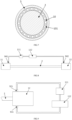
- a connector assembly with liquid cooling function which, as shown in FIGs. 1 to 7 , includes at least one electrical connection skeleton 2 and connectors 1, in which the connector 1 includes a connection terminal 7, two ends of the electrical connection skeleton 2 are respectively electrically connected to connection terminals 7, a protective shell 5 with a shielding effectiveness is sleeved on the periphery of the electrical connection skeleton 2, a cavity 6 is formed between the outer periphery of the electrical connection skeleton 2 and an inner wall of the protective shell 5 with a shielding effectiveness, and the cavity has cooling liquid flowing through it 6.
- the high-voltage cables on most of the connector assembly use multi-core copper cables, which are heavy and expensive, and thus become an obstacle to popularization of new energy automobiles.
- multi-core cable is soft and can be easily processed and wired, due to its coarse diameter and significant weight, the cable may have frequent friction with the automobile shell during driving of the automobile, resulting in damage to the insulation layer of the cable and causing high-voltage discharge, which mildly causes damage to the vehicle and seriously causes serious traffic accidents. Therefore, the multi-core cable structure can be replaced with the cable form of the electrical connection skeleton 2, so that the cable can be fixed on the automobile shell, and may not rub against the automobile shell along with vibration of the automobile, thereby extending the service life of the connector assembly and reducing the accident rate.
- the material of the connection terminal 7 is copper or copper alloy. Copper or copper alloy has high electrical conductivity and is resistant to friction, and at present, the connection part of most electrical devices is made of copper, thus it is necessary to use the connection terminal 7 made of copper or copper alloy for plugging and unplugging connection.
- the connection terminal 7 can be widely used in various electrical transmission scenarios.
- the material of the cooling liquid is an insulating material, such as insulating oil.
- the insulating oil can quickly conduct the high temperature of the electrical connection skeleton 2 to the outside, to achieve the purpose of rapid cooling, and does not electrically connect the electrical connection skeleton 2 and the protective shell, which thus can realize the conductive function of different circuits.
- the material of the electrical connection skeleton 2 is a rigid solid conductor material. That is, the conductor is composed of a wire, and the specific material can be copper or copper alloy, aluminum or aluminum alloy with excellent electrical conductivity.
- the material of the electrical connection skeleton 2 is aluminum or aluminum alloy.
- the electrical connection skeleton 2 made of aluminum or aluminum alloy has the advantages of good rigidity, light weight and high transmission efficiency, especially suitable for the transmission of large current.
- the electrical connection skeleton 2 has a cross-sectional area of 1.5 mm 2 to 240 mm 2 .
- the cross-sectional area of the electrical connection skeleton 2 determines the current that the electrical connection skeleton 2 can conduct.
- the electrical connection skeleton 2 that achieves signal conduction has a small current and a small cross-sectional area.
- the smallest cross-sectional area of the electrical connection skeleton 2 for transmitting signals may reach 1.5 mm 2
- the electrical connection skeleton 2 that achieves power conduction has a high current and a large cross-sectional area.
- the electrical connection skeleton 2 has a largest cross-sectional area of 240 mm 2 .
- the electrical connection skeleton 2 is electrically connected to the connection terminal 7 by welding or crimping.
- the material of the connection terminal 7 is copper or copper alloy, and the material of the electrical connection skeleton 2 is aluminum or aluminum alloy. Copper or copper alloy has high electrical conductivity and is resistant to friction, and at present, the connection part of most electrical devices is made of copper, thus it is necessary to use the connection terminal 7 made of copper or copper alloy for plugging and unplugging connection.
- the connection terminal 7 can be widely used in various electrical transmission scenarios.
- the electrical connection skeleton 2 made of aluminum or aluminum alloy has the advantages of good rigidity, light weight and high transmission efficiency, especially suitable for the transmission of large current.
- the connection terminal 7 and the electrical connection skeleton 2 are connected by welding.
- the welding methods adopted include one or more selected from the group consisting of resistance welding, friction welding, ultrasonic welding, arc welding, laser welding, electron beam welding, pressure diffusion welding and magnetic induction welding.
- the concentrated heat energy or pressure is used to create a fused connection between the connection terminal 7 and the electrical connection skeleton 2, to achieve a stable welding connection.
- the metal inertia of copper is greater than that of aluminum
- the electrode potential difference between copper and aluminum is 1.9997 V
- an electrochemical reaction occurs after the two metals are connected and electrified, causing the aluminum wire to be oxidized gradually, and reducing the mechanical strength and conductivity of the aluminum wire.
- the use of welding can achieve connection of dissimilar materials, and has better conductive effect due to contact position fusion.
- the resistance welding refers to a method that utilizes a strong current passing through the contact point between the electrode and the workpiece, and achieves welding by generating heat from the contact resistance.
- the friction welding refers to a method that utilizes the heat generated by the friction of the workpiece contact surface as the heat source to make the workpiece undergo plastic deformation under the action of pressure, to achieve welding.
- the ultrasonic welding refers to a method that utilizes high-frequency vibration waves transmitted to the surfaces of two objects to be welded, and under pressure, the surfaces of two objects rub against each other to form a fusion between molecular layers.
- the arc welding refers to a method that electric arc is taken as the heat source and the physical phenomenon of air discharges is utilized to convert electrical energy into thermal and mechanical energy required for welding, so as to achieve the purpose of connecting metal, and the main methods include shielded metal arc welding, submerged arc welding, gas shielded welding and so on.
- the laser welding method refers to an efficient and precise welding method that utilizes a laser beam with high energy density as a heat source.
- the friction welding method refers to a method of welding by using the heat generated by the friction of the workpiece contact surface as the heat source to make the workpiece produce plastic deformation under the action of pressure.
- the electron beam welding method refers to a method that utilizes accelerated and focused electron beam to bombard the welding surface placed in vacuum or non-vacuum, so that the welded workpiece is melted to achieve welding.
- the pressure welding method is a method of applying pressure to a weldment to make the joint surfaces be in contact closely and undergo a certain plastic deformation, thereby completing the welding.
- the magnetic induction welding method refers to a method that instantaneous high-speed collision occurs between two workpieces to be welded under the action of strong pulsed magnetic field, and when surface of the material is subjected to high pressure waves, the atoms of the two materials meet in the interatomic distance, thus forming a stable metallurgical bond at the interface, which is a type of solid-state cold welding that can weld conductive metals with similar or dissimilar properties together.
- the crimping refers to the production process that after the electrical connection skeleton and the connection terminal are assembled, the two are stamped into an integral whole by using a crimping machine.
- the advantage of crimping is its production capability, and a large amount of products with stable quality can be produced quickly by using an automatic crimping machine.
- the material of the protective shell 5 is a rigid conductive material.
- the shape and size of the rigid conductor material do not change during motion and under applied force, and the relative position of the internal points does not change, the physical performance is stable, and the power transmission efficiency is also stable.
- the material of the protective shell 5 is metal or conductive plastic.
- the electrically conductive plastic is conductive plastic or conductive rubber containing metal particles. The advantage of using the electrically conductive plastic is that it can facilitate injection molding, and use of metal material can obtain better strength and protect the cavity. The user may select an appropriate material for the protective shell 5 based on their needs.
- the connector further includes a shielding inner shell 4 inside, and material of the shielding inner shell 4 is a conductive material.
- the shielding inner shell 4 is electrically connected to the protective shell 5 with a shielding effectiveness to form a complete shielding device.
- the shielding device may play the role of a shielding layer, and may effectively shield the electromagnetic interference generated by electrification of the electrical connection skeleton 2 and the connection terminal 7, which saves the use of the shielding net and reduces the cost of the connector assembly.
- the material of the shielding inner shell 4 is metal or electrically conductive plastic.
- the electrically conductive plastic is a conductive plastic or a conductive rubber which contains metal particles. The advantage of using the electrically conductive plastics is that it can be facilitated injection molding, and the user can select the shielding inner shell 4 made of appropriate material based on their needs.
- the conductive plastic is a polymeric material containing conductive particles.
- the material of the conductive particles contains one or more selected from the group consisting of a metal, a conductive ceramic, a carbon-containing conductor, a solid electrolyte, and a mixed conductor.
- the material of the polymeric material contains one or more selected from the group consisting of tetraphenyl ethylene, polyvinyl chloride, polyethylene, polyamide, polytetrafluoroethylene, an tetrafluoroethylene-hexafluoroethylene copolymer, an ethylene-tetrafluoroethylene copolymer, polypropylene, polyvinylidene fluoride, polyurethane, poly(terephthalic acid)(i.e.,polyethylene terephthalate), polyurethane elastomers, styrene block copolymer, perfluoroalkoxy alkane, chlorinated polyethylene, polyphenylene sulfide, polystyrene, crosslinked polyolefin, EPR (ethylene propylene rubber), an ethylenevinyl acetate copolymer, chloroprene rubber, natural rubber, styrene butadiene rubber, nitrile butadiene rubber, silicone rubber, but
- the material of the metal contains one or more selected from the group consisting of nickel, cadmium, zirconium, chromium, cobalt, manganese, aluminum, tin, titanium, zinc, copper, silver, gold, phosphorus, tellurium, beryllium.
- the inventor conducts tests by using metal particles of the same specification and size and different materials to make samples of the shielding inner shell 4, to test the electric conductivity of the shielding inner shell 4 respectively, and the experimental results are shown in Table 1 below. In this embodiment, the electric conductivity of the shielding inner shell 4 being greater than 99% is regarded as an ideal value.
- Table 1 Influence of metal particles of different materials on the conductivity of the shielding inner shell 4 Metal of different materials Gold Silve r Coppe r Nic kel Titaniu m Tin Alumin um Cadmiu m Zirconiu m Chromi um Cobalt Manganese. Zinc Tell uriu m Bery lliu m Palladiu m Conductivity of shielding inner shell (%) 99.8 99.9 99.8 99.5 99.5 99.5 99.6 99.3 99.2 99.2 99.4 99.5 99.3 99.4 99.4 99.2
- the electric conductivity of the conductive plastic made of the selected different metal particles is within the range of the ideal value.
- phosphorus is a non-metal material and may not be directly used as material of the conductive plating, but it can be added into other metals to form alloy to improve the conductive and mechanical properties of the metal itself. Therefore, the inventor sets that the material of the metal particles contains one or more selected from the group consisting of nickel, cadmium, zirconium, chromium, cobalt, manganese, aluminum, tin, titanium, zinc, copper, silver, gold, phosphorus, tellurium, beryllium.
- the carbon-containing conductor contains one or more selected from the group consisting of graphite powder, carbon nanotube material, graphite-silver composite, graphene-silver composite, and graphene material.
- Graphite powder is a kind of mineral powder, mainly composed of a carbon simple substance, soft, black and gray; Graphite powder is a good non-metallic conductive material.
- Carbon nanotubes have good electrical conductivity, and because the carbon nanotubes have the same structure as the lamellar structure of graphite, they have good electrical properties. Particularly, graphene has extremely high electrical properties, and the carbon-containing conductor containing the graphite powder, the carbon nanotubes or graphene has high conductivity and good shielding performance, which can achieve electromagnetic shielding to the electrical connection skeleton 2 very well.
- the protective shell 5 is electrically connected to the shielding inner shell 4 by crimping or welding.
- Aluminum or aluminum alloy material has good conductive property, light weight and low price.
- the shielding inner shell 4 made of aluminum or aluminum alloy can play a good shielding effectiveness to prevent the electromagnetic radiation of the connection terminal 7 and the electrical connection skeleton 2 from affecting other devices.
- Crimping is a production process that after the shielding inner shell 4 and the protective shell 5 with a shielding effectiveness are assembled, the two are stamped into an integral whole using a crimping machine.
- the advantage of crimping is good manufacturability, and a large amount of products with stable quality can be produced quickly by using an automatic crimping machine.
- the welding method is basically the same as the welding method of the connection terminal 7 and the electrical connection skeleton 2, and thus is not repeated.
- an impedance between the protective shell 5 and the shielding inner shell 4 is less than 80 mS2.
- the impedance between the protective shell 5 and the shielding inner shell 4 shall be as small as possible, so that the current generated by the shielding inner shell 4 may flow back without obstruction to the energy source or the grounding position. If the impedance between the protective shells and the shielding inner shell 4 is large, high current may be generated between the protective shell 5 and the shielding inner shell 4, resulting in a large radiation at the cable connection.
- the inventor selects the electrical connection skeleton 2, the connector 1 and the connection terminal 7 of the same specification, and selects different impedances between the protective shell 5 and the shielding inner shell 4 to make a series of samples to respectively test the shielding effectiveness, and the experimental results are shown in Table 2 below.
- the shielding performance value greater than 40 dB is regarded as the ideal value.
- the test method of the shielding performance value is to use test instrument to output a signal value (this value is the test value 2) to the electrical connection skeleton 2, and to provide a detection device outside the electrical connection skeleton 2, and the detection device detects a signal value (this value is the test value 1).
- Shielding performance value test value 2 - test value 1.
- Table 2 Influence of impedance between the protective shell 5 and the shielding inner shell 4 on the shielding performance Measuring parameter Impedance between the protective shell 5 and the shielding inner shell 4 (mS2) 5 10 20 30 40 50 60 70 80 90 100 Shielding performance value (dB) 76 74 72 66 61 57 52 49 38 32 28
- the shielding performance value is less than 40 dB, which does not meet the ideal value requirement; while when the impedance value between the protective shell 5 and the shielding inner shell 4 is less than 80 mQ, the shielding performance value all meets the ideal value requirements, and the trend is getting better and better. Therefore, the inventor sets the impedance between the protective shell 5 and the shielding inner shell 4 to be less than 80 mS2.
- the transfer impedance of the protective shell 5 is less than 100 mQ.
- the shielding material usually uses the transfer impedance to characterize the shielding effectiveness of the protective shell 5, and the smaller the transfer impedance is, the better the shielding effectiveness is.
- the transfer impedance of the protective shell 5 is defined as the ratio of the differential mode voltage U induced by the shield per unit length to the current Is passing through the shield surface, i.e.,
- the inventor selects the electrical connection skeleton 2, the connector 1 and the connection terminal 7 of the same specification, and uses the protective shell 5 having different transfer impedance values to make a series of samples to respectively test the shielding effectiveness, and the experimental results are shown in Table 3 below.
- the shielding performance value greater than 40 dB is the ideal value.
- the test method of the shielding performance value is to use test instrument to output a signal value (this value is the test value 2) to the electrical connection skeleton 2, and to provide a detection device outside the electrical connection skeleton 2, and the detection device detects a signal value (this value is the test value 1).
- Shielding performance value test value 2 - test value 1.
- Table 3 Influence of transfer impedance of the protective shell 5 on the shielding performance Measuring parameter Transfer impedance of the protective shell 5 (m ⁇ ) 20 30 40 50 60 70 80 90 100 110 120 Shielding performance value (dB) 79 76 71 67 63 58 53 46 36 30 26
- the shielding performance value of the protective shell 5 is less than 40 dB, which does not meet the requirement of the ideal value; and when the transfer impedance value of the protective shell 5 is less than 100 mQ, the shielding performance values of each of protective shells 5 meets the requirement of the ideal value, and the trend is getting better and better, therefore, the inventor sets the transfer impedance of the protective shell 5 to be less than 100 mS2.
- the transfer impedance of the shielding inner shell 4 is less than 100 mQ.
- the inventor selects the electrical connection skeleton 2, the connector 1 and the connection terminal 7 of the same specification, and uses the shielding inner shell 4 having different transfer impedance values to make a series of samples to respectively test the shielding effectiveness, and the experimental results are shown in Table 4 below.
- the shielding performance value greater than 40 dB is the ideal value.
- the test method of the shielding performance value is to use test instrument to output a signal value (this value is the test value 2) to the electrical connection skeleton 2, and to provide a detection device outside the shielding inner shell 4, and the detection device detects a signal value (this value is the test value 1).
- Shielding performance value test value 2 - test value 1.
- Table 4 Influence of transfer impedance of the shielding inner shell 4 on the shielding performance Measuring parameter Transfer impedance of shielding inner shell 4 (mS2) 20 30 40 50 60 70 80 90 100 110 120 Shielding performance value (dB) 79 76 71 66 63 58 55 46 37 31 27
- the shielding performance value of the shielding inner shell 4 is less than 40 dB, which does not meet the requirement of the ideal value; and when the transfer impedance value of the shielding inner shell 4 is less than 100 mQ, the shielding performance values of each of shielding inner shells 4 meets the requirement of the ideal value, and the trend is getting better and better, therefore, the inventor sets the transfer impedance of the shielding inner shell 4 to be less than 100 mS2.
- the number of the electrical connection skeleton 2 is one
- the connector 1 includes a first connector 11 and a second connector 12 that are connected to two ends of the electrical connection skeleton 2, respectively
- the first connector 11 and the second connector 12 are internally provided with an adapter cavity 94
- the adapter cavity 94 is in communication with the cavity 6
- the first connector 11 is provided with an inlet pipe 941 that is in communication with the adapter cavity 94
- the second connector 12 is provided with an outlet pipe 942 that is in communication with the adapter cavity.
- the cooling liquid driven by a driving device, enters the adapter cavity 94 of the first connector 11 from the inlet pipe 941, then enters the adapter cavity 94 of the second connector 12 from the cavity 6 of one electrical connection skeleton 2, then is exported by the outlet pipe 942 of the second connector, and then enters the first connector 11 from the driving device, to form a complete cooling cycle.
- the number of the electrical connection skeleton 2 is at least two
- the connector 1 includes a first connector 11 and a second connector 12 that are connected to two ends of the electrical connection skeleton 2, respectively
- the first connector 11 is internally provided with a communicating rotary chamber 91
- the rotary chamber 91 is in communication with the cavity 6 of each of the electrical connection skeletons 2
- the second connector 12 is internally provided with a liquid inlet cavity 92 and a liquid outlet cavity 93 that are isolated from each other, and the liquid inlet cavity 92 and the liquid outlet cavity 93 are respectively in communication with the cavities 6 of the individual electrical connection skeletons 2.
- the cooling loop consists of two electrical connection skeletons 2, where the cooling liquid, driven by the driving device, enters the liquid inlet cavity 92 of the second connector 12, then enters the rotary chamber 91 of the first connector 11 from the cavity 6 of one electrical connection skeleton 2, then enters the cavity 6 of the other electrical connection skeleton 2, and then enters the liquid outlet cavity 93, then is cooled and enters the liquid inlet cavity 92 from the driving device, to form a complete cooling cycle.
- a side wall of the liquid inlet cavity 92 is provided with a liquid inlet pipe 921 that is in communication with outside of the connector 1
- a side wall of the liquid outlet cavity 93 is provided with a liquid outlet pipe 931 that is in communication with the outside of the connector 1.
- the cooling liquid enters the liquid inlet cavity 92 from the liquid inlet pipe 921, and then flows out of the liquid outlet cavity 93 from the liquid outlet pipe 931.
- a sealing structure 8 is arranged between the connector 1 and the protective shell 5. As shown in FIG. 4 , the sealing structure 8 seals the connection point. The sealing structure 8 can prevent the cooling liquid from leaking from the connection point of the connector 1 and the protective shell 5.
- the sealing structure 8 may be a sealing ring.
- At least one support ring 10 is arranged inside the cavity 6. As shown in FIG. 6 , an inner wall of the support ring 10 is in contact with the outer periphery of the electrical connection skeleton 2, and an outer wall of the support ring 10 is in contact with the inner wall of the protective shell 5.
- the support ring 10 is capable of supporting the cavity 6 to prevent the cavity 6 from being narrowed due to external extrusion, which results in a decrease in the cooling efficiency of the connector assembly, at the same time, the support ring 10 is capable of avoiding short circuit caused by contact between the electrical connection skeleton 2 and the protective shell 5.
- the number of the support ring 10 may be set to be plural.
- the support ring 10 may firstly be fixed on the electrical connection skeleton 2 and then be sleeved with the protective shell 5, and next the protective shell 5 is squeezed such that the outer wall of the support ring 10 is in contact with the inner wall of the protective shell 5.
- the support ring 10 is provided with at least one through hole 101 in an axial direction of the electrical connection skeleton 2. As shown in FIG. 7 , in order to prevent the support ring 10 from blocking the flow of the cooling liquid that may result in a decrease in the cooling efficiency of the connector assembly, the support ring 10 is provided with at least one through hole 101 in an axial direction of the electrical connection skeleton 2, which is capable of causing the cooling liquid to pass through the support ring 10 smoothly and obtain the cooling effect.
- a sum of cross-sectional areas of the through holes 101 accounts for 23% to 90% of the cross-sectional area of the cavity 6. If the sum of cross-sectional areas of the through holes 101 is too large, the supporting force of the supporting ring 10 will be insufficient; if the sum of cross-sectional areas of the through holes 101 is too small, the cooling efficiency will be insufficient.
- the inventor conducts relevant tests by selecting the same electrical connection skeleton 2 with the same cavity 6, the support rings 10 with different through holes 101 are arranged in cavity 6, and a force of 80 N is applied to observe whether the cavity 6 deforms. If the cavity 6 deforms, the result of the test is regarded as being not qualified.
- the temperature rise of the electrical connection skeleton 2 is greater than 50.2K, which is regarded as being unqualified;
- the ratio of the sum of cross-sectional areas of the through holes 101 to cross-sectional area of the cavity 6 is greater than 90%, the cavity 6 may be deformed under the acting force of 80 N, which may easily cause the cooling rate to decrease, and even the cooling liquid to leak. Therefore, the inventor exemplarily selects that the ratio of the sum of cross-sectional areas of the through holes 101 to cross-sectional area of the cavity 6 is 23% to 90%.
- the electrical connection skeleton 2 has at least one bending position, the bending position has an arc, and support rings 10 are arranged at least at both ends of the arc and at an intermediate position of the arc, respectively.
- the arc formed at the bending position of the electrical connection skeleton 2 is more likely to be squeezed, thus the support rings10 are arranged at both ends of the arc and at an intermediate position of the arc to play a better supporting role.
- the electrical connection skeleton 2 has a cross section in a shape of one or more selected from the group consisting of circular, oval, rectangular, polygonal, A-shaped, B-shaped, D-shaped, M-shaped, N-shaped, O-shaped, S-shaped, E-shaped, F-shaped, H-shaped, K-shaped, L-shaped, T-shaped, P-shaped, U-shaped, V-shaped, W-shaped, X-shaped, Y-shaped, Z-shaped, semi-arc, arc, and waved shape.
- electrical connection skeletons 2 with different cross sections can be used according to the need.
- the cross-section shape of the electrical connection skeleton 2 is a polygon, and corners of the polygon are all rounded or chamfered, which can prevent its sharp parts from causing damage to the insulation layer or the shielding layer.
- the electrical connection skeleton 2 includes at least one bending portion, to meet the needs of installation in the vehicle body.
- the outer diameter of the cavity 6 is 1.02 to 1.3 times of the outer diameter of the electrical connection skeleton 2. If the outer diameter of the cavity 6 is too small and the cooling liquid flowing through is not enough, the cooling efficiency is insufficient.
- the inventor conducts relevant tests by selecting the same electrical connection skeleton 2 and cavities 6 with different outer diameters, into which the same cooling liquid flows at the same speed. The temperature rise is measured after the electrical connection skeleton 2 is electrified, and the temperature rise being less than 50 K is regarded as a qualified value. The results are shown in Table 7.
- Table 7 Influence of ratio of the outer diameter of the cavity 6 to the outer diameter of the electrical connection skeleton 2 on the temperature rise of the electrical connection skeleton Ratio of the outer diameter of the cavity 6 to the outer diameter of the electrical connection skeleton 2 (%) 1 1.02 1.06 1.10 1.11 1.13 1.15 1.17 1.20 1.25 1.28 1.3 1.31 Temperature rise of the electrical connection skeleton (K) 50.2 49.6 47.5 44 41.2 39.8 38.5 37.1 33.2 30.9 27.5 26.8 26.8
- the temperature rise of the electrical connection skeleton 2 is greater than 50 K, which is regarded as being not qualified; and when the ratio of the outer diameter of the cavity 6 to the outer diameter of the electrical connection skeleton 2 is greater than 1.3, the temperature rise of the electrical connection skeleton 2 has no significant change, and a thicker cavity 6 may increase the cost and weight of the vehicle body, thus the inventor exemplarily selects that the outer diameter of the cavity 6 is 1.02 to 1.3 times the outer diameter of the electrical connection skeleton 2.
- the cooling liquid contains one or more selected from the group consisting of purified water, silicone oil, fluorinated liquid, ethylene glycol, castor oil, coconut oil, corn oil, cottonseed oil, linseed oil, olive oil, palm oil, peanut oil, grapeseed oil, rapeseed oil, safflower oil, sunflower oil, soybean oil, high oleic acid variants of various vegetable oils, decene-4-carboxylic-acid, decenoic acid, lauroleic acid, combined spicebush root acid, tetradecenoic acid, physeteranic acid, crude fatty acid, palmitoleic acid, petroselinic acid, oleic acid, octadecenoic acid, g professionnoic acid, gondoic acid, cetoleic acid, erucic acid, and nervonic acid, glycerolgly, transformer oil, axle oil, internal combustion engine oil, or compressor oil.
- purified water silicone oil, fluorinated liquid
- a cooling rate of the cooling liquid on the electrical connection 2 is 0.05 to 5 K/s.
- the inventor selects 10 electrical connection skeletons 2 that have the same cross-sectional area, are made of the same material and have the same length, and are electrified by the same current, uses cooling liquids with different cooling rates to cool the electrical connection skeleton 2, and reads temperature rise values of individual electrical connection skeletons 2, which are recorded in Table 8.
- the experimental method is that, in a closed environment, the electrical connection skeletons 2 with the cooling liquids at different cooling rates are electrified with the same current, to record the temperature before electrification and the temperature when it is stabilized after electrification, and to calculate a difference and obtain an absolute value.
- a temperature rise of less than 50K is a qualified value.
- Table 8 Influence of cooling liquids at different cooling rates on temperature rise of the electrical connection skeleton 2 Cooling liquid cooling rate (K/min) 0.01 0.03 0.05 0.1 0.3 0.5 1 2 3 4 5 6 7 Temperature rise of the electrical connection skeleton 2 (K) 63.0 58.5 49.6 48.7 47.1 45.5 41.4 37.7 33.3 30.9 27.5 27.5 27.4
- one of the connectors is a charging socket.
- One end of the electrical connection skeleton 2 is connected to the connection terminal 7 in the charging socket, and the other end thereof is connected to the vehicle-mounted battery through the connection terminal 7 to form the charging line of the automobile.
- the disclosure further provides a vehicle including a connector assembly with liquid cooling function, a circulating pump 111 and a cooling device 112 as described above, wherein the cavity 6 is in communication with the circulating pump 111 and the cooling device 112.
- the circulating pump 111 feeds the cooling liquid into the cavity 6 to cool the electrical connection skeleton 2, and the cooling liquid flows out of the cavity 6.
- the temperature of the cooling liquid has been relatively high, and after entering the cooling device 112, the temperature of the cooling liquid drops and again the cooling liquid is sent into the cavity by the circulating pump 111, thereby forming a complete cooling cycle.
- the inlet pipe 941 is in communication with a liquid inlet of the circulating pump 111
- a liquid outlet of the circulating pump 111 is in communication with a liquid inlet of the cooling device 112
- a liquid outlet of the cooling device 112 is in communication with the outlet pipe 942.
- the circulating pump 111 drives the cooling liquid to enter the cooling device 112, and then flow through the liquid outlet of the cooling device 112 to enter the outlet pipe 942, and then flow through the cavity 6 to cool the electrical connection skeleton 2 and then enter the circulating pump 111 through the inlet pipe 941, to form a complete cooling cycle.
- the liquid inlet pipe 921 is in communication with the liquid inlet of the circulating pump 111
- the liquid outlet of the circulating pump 111 is in communication with the liquid inlet of the cooling device 112
- the liquid outlet of the cooling device 112 is in communication with the liquid outlet pipe 931.
- the circulating pump 111 drives the cooling liquid to enter the cooling device 112, then flow through the liquid outlet pipe 931 to enter the liquid outlet cavity 93, then enter the cavity 6 of one electrical connection skeleton 2, enter the rotary chamber 91, then enter the cavity 6 of the other electrical connection skeleton 2, and finally flow through the liquid inlet pipe 921 of the second connector 12 to enter the circulating pump 111, thereby forming a complete cooling cycle.
- this cycle can also be reversed, that is, the circulating pump 111 drives the cooling liquid to firstly enter the liquid inlet pipe 921, and finally enter the cooling device 112, thereby completing the cooling cycle as well.
Landscapes
- Engineering & Computer Science (AREA)
- Power Engineering (AREA)
- Transportation (AREA)
- Mechanical Engineering (AREA)
- Connector Housings Or Holding Contact Members (AREA)
- Details Of Connecting Devices For Male And Female Coupling (AREA)
Applications Claiming Priority (2)
| Application Number | Priority Date | Filing Date | Title |
|---|---|---|---|
| CN202210250054.8A CN114709686A (zh) | 2022-03-14 | 2022-03-14 | 一种液冷连接器总成及一种车辆 |
| PCT/CN2023/081366 WO2023174282A1 (fr) | 2022-03-14 | 2023-03-14 | Ensemble connecteur de refroidissement de liquide et véhicule |
Publications (2)
| Publication Number | Publication Date |
|---|---|
| EP4496154A1 true EP4496154A1 (fr) | 2025-01-22 |
| EP4496154A4 EP4496154A4 (fr) | 2025-08-06 |
Family
ID=82168759
Family Applications (1)
| Application Number | Title | Priority Date | Filing Date |
|---|---|---|---|
| EP23769784.2A Pending EP4496154A4 (fr) | 2022-03-14 | 2023-03-14 | Ensemble connecteur de refroidissement de liquide et véhicule |
Country Status (5)
| Country | Link |
|---|---|
| US (1) | US20250206164A1 (fr) |
| EP (1) | EP4496154A4 (fr) |
| CN (1) | CN114709686A (fr) |
| MX (1) | MX2024011363A (fr) |
| WO (1) | WO2023174282A1 (fr) |
Families Citing this family (4)
| Publication number | Priority date | Publication date | Assignee | Title |
|---|---|---|---|---|
| CN114709686A (zh) * | 2022-03-14 | 2022-07-05 | 长春捷翼汽车零部件有限公司 | 一种液冷连接器总成及一种车辆 |
| CN115359962A (zh) * | 2022-08-12 | 2022-11-18 | 长春捷翼汽车零部件有限公司 | 一种防火冷却线缆 |
| CN115440430A (zh) * | 2022-08-12 | 2022-12-06 | 长春捷翼汽车零部件有限公司 | 一种液冷线缆 |
| DE102024110988A1 (de) * | 2024-04-19 | 2025-10-23 | Leoni Kabel Gmbh | Kühlschlauch mit unterschiedlicher Flexibilität |
Family Cites Families (15)
| Publication number | Priority date | Publication date | Assignee | Title |
|---|---|---|---|---|
| US5591937A (en) * | 1994-12-02 | 1997-01-07 | Hughes Aircraft Company | High power, high frequency transmission cable breach detection |
| DE202015009531U1 (de) * | 2015-11-19 | 2018-02-27 | Dr. Ing. H.C. F. Porsche Aktiengesellschaft | Elektrisches Ladekabel für ein Kraftfahrzeug |
| CN108199162B (zh) * | 2017-12-22 | 2024-01-26 | 深圳市沃尔新能源电气科技股份有限公司 | 液冷充电插座 |
| WO2019184882A1 (fr) * | 2018-03-26 | 2019-10-03 | 洛阳正奇机械有限公司 | Câble à refroidissement par liquide froid parallèle destiné à l'utilisation exclusive d'un pôle positif et d'un pôle négatif de pile de charge à haute puissance |
| DE102018215875A1 (de) * | 2018-09-18 | 2020-03-19 | Bayerische Motoren Werke Aktiengesellschaft | Ladestrangeinrichtung für eine Batterie eines Kraftfahrzeugs |
| CN110696651B (zh) * | 2019-09-27 | 2025-04-08 | 中航光电科技股份有限公司 | 一种充电端子液冷结构 |
| CN111653893A (zh) * | 2020-05-20 | 2020-09-11 | 中航光电科技股份有限公司 | 一种液冷端子结构 |
| CN212304003U (zh) * | 2020-05-20 | 2021-01-05 | 中航光电科技股份有限公司 | 一种焊接端子液冷结构 |
| CN112566472B (zh) * | 2020-12-21 | 2024-01-30 | 威海市泓淋电力技术股份有限公司 | 一种大功率充电用非接触式液冷系统及其液冷方法 |
| CN214956156U (zh) * | 2021-07-06 | 2021-11-30 | 上海艾姆倍新能源科技有限公司 | 一种柔性液冷线缆 |
| CN113708159A (zh) * | 2021-08-21 | 2021-11-26 | 长春捷翼汽车零部件有限公司 | 一种屏蔽线缆连接结构 |
| CN114709686A (zh) * | 2022-03-14 | 2022-07-05 | 长春捷翼汽车零部件有限公司 | 一种液冷连接器总成及一种车辆 |
| CN217823617U (zh) * | 2022-03-14 | 2022-11-15 | 长春捷翼汽车零部件有限公司 | 一种液冷连接器总成及一种车辆 |
| CN218334622U (zh) * | 2022-03-14 | 2023-01-17 | 长春捷翼汽车零部件有限公司 | 一种具有液冷功能的连接器总成及一种车辆 |
| CN114709689A (zh) * | 2022-03-14 | 2022-07-05 | 长春捷翼汽车零部件有限公司 | 一种具有液冷功能的连接器总成及一种车辆 |
-
2022
- 2022-03-14 CN CN202210250054.8A patent/CN114709686A/zh active Pending
-
2023
- 2023-03-14 EP EP23769784.2A patent/EP4496154A4/fr active Pending
- 2023-03-14 US US18/847,189 patent/US20250206164A1/en active Pending
- 2023-03-14 WO PCT/CN2023/081366 patent/WO2023174282A1/fr not_active Ceased
-
2024
- 2024-09-13 MX MX2024011363A patent/MX2024011363A/es unknown
Also Published As
| Publication number | Publication date |
|---|---|
| MX2024011363A (es) | 2024-12-06 |
| EP4496154A4 (fr) | 2025-08-06 |
| US20250206164A1 (en) | 2025-06-26 |
| CN114709686A (zh) | 2022-07-05 |
| WO2023174282A1 (fr) | 2023-09-21 |
Similar Documents
| Publication | Publication Date | Title |
|---|---|---|
| EP4496154A1 (fr) | Ensemble connecteur de refroidissement de liquide et véhicule | |
| EP4496150A1 (fr) | Ensemble connecteur ayant une fonction de refroidissement de liquide et véhicule | |
| EP4496146A1 (fr) | Ensemble raccord à fonction de refroidissement par liquide et véhicule | |
| EP4496149A1 (fr) | Ensemble connecteur ayant un milieu de refroidissement à semi-conducteurs, et véhicule | |
| CN218334622U (zh) | 一种具有液冷功能的连接器总成及一种车辆 | |
| WO2023174293A1 (fr) | Ensemble connecteur comportant un milieu de refroidissement solide, et véhicule | |
| EP4496153A1 (fr) | Ensemble de transmission d'énergie électrique et véhicule | |
| EP4496140A1 (fr) | Ensemble raccord à fonction de refroidissement par liquide et véhicule | |
| EP4496152A1 (fr) | Ensemble de transmission d'énergie électrique et véhicule | |
| EP4496144A1 (fr) | Ensemble connecteur et procédé de traitement | |
| EP4496148A1 (fr) | Ensemble connecteur utilisant un nouveau matériau de blindage, et véhicule | |
| EP4495956A1 (fr) | Ensemble de transmission d'énergie électrique et véhicule | |
| EP4495957A1 (fr) | Système de transmission d'énergie électrique et automobile | |
| EP4496147A1 (fr) | Nouvel ensemble connecteur de blindage ignifuge et véhicule | |
| CN217823622U (zh) | 一种具有固态冷却介质的连接器总成及一种车辆 | |
| CN217823617U (zh) | 一种液冷连接器总成及一种车辆 | |
| CN217984006U (zh) | 一种新型屏蔽材料的连接器总成及一种车辆 | |
| CN217823615U (zh) | 一种具有液冷功能的连接器总成及一种车辆 | |
| CN218334623U (zh) | 一种具有液冷功能的连接器总成及一种车辆 | |
| EP4496141A1 (fr) | Ensemble connecteur à base d'un nouveau matériau de blindage et véhicule | |
| EP4496145A1 (fr) | Ensemble connecteur ayant un milieu de refroidissement à semi-conducteurs, et véhicule | |
| CN217823619U (zh) | 一种具有固态冷却介质的连接器总成及一种车辆 | |
| CN217823613U (zh) | 一种具有固态冷却介质的连接器总成及一种车辆 |
Legal Events
| Date | Code | Title | Description |
|---|---|---|---|
| STAA | Information on the status of an ep patent application or granted ep patent |
Free format text: STATUS: THE INTERNATIONAL PUBLICATION HAS BEEN MADE |
|
| PUAI | Public reference made under article 153(3) epc to a published international application that has entered the european phase |
Free format text: ORIGINAL CODE: 0009012 |
|
| STAA | Information on the status of an ep patent application or granted ep patent |
Free format text: STATUS: REQUEST FOR EXAMINATION WAS MADE |
|
| 17P | Request for examination filed |
Effective date: 20241014 |
|
| AK | Designated contracting states |
Kind code of ref document: A1 Designated state(s): AL AT BE BG CH CY CZ DE DK EE ES FI FR GB GR HR HU IE IS IT LI LT LU LV MC ME MK MT NL NO PL PT RO RS SE SI SK SM TR |
|
| DAV | Request for validation of the european patent (deleted) | ||
| DAX | Request for extension of the european patent (deleted) | ||
| P01 | Opt-out of the competence of the unified patent court (upc) registered |
Free format text: CASE NUMBER: APP_22605/2025 Effective date: 20250513 |
|
| A4 | Supplementary search report drawn up and despatched |
Effective date: 20250707 |
|
| RIC1 | Information provided on ipc code assigned before grant |
Ipc: H01R 31/06 20060101AFI20250701BHEP Ipc: H01R 13/73 20060101ALI20250701BHEP Ipc: B60L 53/18 20190101ALI20250701BHEP Ipc: B60L 53/16 20190101ALI20250701BHEP Ipc: B60L 53/302 20190101ALI20250701BHEP Ipc: B60R 16/02 20060101ALI20250701BHEP Ipc: H01R 13/00 20060101ALI20250701BHEP Ipc: H01R 13/533 20060101ALI20250701BHEP |
|
| STAA | Information on the status of an ep patent application or granted ep patent |
Free format text: STATUS: EXAMINATION IS IN PROGRESS |