EP4497508A1 - Dispositif de distribution de fluide - Google Patents
Dispositif de distribution de fluide Download PDFInfo
- Publication number
- EP4497508A1 EP4497508A1 EP23188135.0A EP23188135A EP4497508A1 EP 4497508 A1 EP4497508 A1 EP 4497508A1 EP 23188135 A EP23188135 A EP 23188135A EP 4497508 A1 EP4497508 A1 EP 4497508A1
- Authority
- EP
- European Patent Office
- Prior art keywords
- valve element
- dispensing device
- fluid
- liner
- channel
- Prior art date
- Legal status (The legal status is an assumption and is not a legal conclusion. Google has not performed a legal analysis and makes no representation as to the accuracy of the status listed.)
- Pending
Links
Images

Classifications
-
- B—PERFORMING OPERATIONS; TRANSPORTING
- B05—SPRAYING OR ATOMISING IN GENERAL; APPLYING FLUENT MATERIALS TO SURFACES, IN GENERAL
- B05B—SPRAYING APPARATUS; ATOMISING APPARATUS; NOZZLES
- B05B1/00—Nozzles, spray heads or other outlets, with or without auxiliary devices such as valves, heating means
- B05B1/34—Nozzles, spray heads or other outlets, with or without auxiliary devices such as valves, heating means designed to influence the nature of flow of the liquid or other fluent material, e.g. to produce swirl
- B05B1/3405—Nozzles, spray heads or other outlets, with or without auxiliary devices such as valves, heating means designed to influence the nature of flow of the liquid or other fluent material, e.g. to produce swirl to produce swirl
- B05B1/341—Nozzles, spray heads or other outlets, with or without auxiliary devices such as valves, heating means designed to influence the nature of flow of the liquid or other fluent material, e.g. to produce swirl to produce swirl before discharging the liquid or other fluent material, e.g. in a swirl chamber upstream the spray outlet
- B05B1/3421—Nozzles, spray heads or other outlets, with or without auxiliary devices such as valves, heating means designed to influence the nature of flow of the liquid or other fluent material, e.g. to produce swirl to produce swirl before discharging the liquid or other fluent material, e.g. in a swirl chamber upstream the spray outlet with channels emerging substantially tangentially in the swirl chamber
- B05B1/3426—Nozzles, spray heads or other outlets, with or without auxiliary devices such as valves, heating means designed to influence the nature of flow of the liquid or other fluent material, e.g. to produce swirl to produce swirl before discharging the liquid or other fluent material, e.g. in a swirl chamber upstream the spray outlet with channels emerging substantially tangentially in the swirl chamber the channels emerging in the swirl chamber perpendicularly to the outlet axis
-
- B—PERFORMING OPERATIONS; TRANSPORTING
- B05—SPRAYING OR ATOMISING IN GENERAL; APPLYING FLUENT MATERIALS TO SURFACES, IN GENERAL
- B05B—SPRAYING APPARATUS; ATOMISING APPARATUS; NOZZLES
- B05B11/00—Single-unit hand-held apparatus in which flow of contents is produced by the muscular force of the operator at the moment of use
- B05B11/0005—Components or details
- B05B11/0062—Outlet valves actuated by the pressure of the fluid to be sprayed
- B05B11/0064—Lift valves
- B05B11/0067—Lift valves having a valve seat located downstream the valve element
-
- B—PERFORMING OPERATIONS; TRANSPORTING
- B05—SPRAYING OR ATOMISING IN GENERAL; APPLYING FLUENT MATERIALS TO SURFACES, IN GENERAL
- B05B—SPRAYING APPARATUS; ATOMISING APPARATUS; NOZZLES
- B05B1/00—Nozzles, spray heads or other outlets, with or without auxiliary devices such as valves, heating means
- B05B1/02—Nozzles, spray heads or other outlets, with or without auxiliary devices such as valves, heating means designed to produce a jet, spray, or other discharge of particular shape or nature, e.g. in single drops, or having an outlet of particular shape
- B05B1/06—Nozzles, spray heads or other outlets, with or without auxiliary devices such as valves, heating means designed to produce a jet, spray, or other discharge of particular shape or nature, e.g. in single drops, or having an outlet of particular shape in annular, tubular or hollow conical form
-
- B—PERFORMING OPERATIONS; TRANSPORTING
- B05—SPRAYING OR ATOMISING IN GENERAL; APPLYING FLUENT MATERIALS TO SURFACES, IN GENERAL
- B05B—SPRAYING APPARATUS; ATOMISING APPARATUS; NOZZLES
- B05B11/00—Single-unit hand-held apparatus in which flow of contents is produced by the muscular force of the operator at the moment of use
- B05B11/0005—Components or details
- B05B11/0027—Means for neutralising the actuation of the sprayer ; Means for preventing access to the sprayer actuation means
- B05B11/0032—Manually actuated means located downstream the discharge nozzle for closing or covering it, e.g. shutters
-
- B—PERFORMING OPERATIONS; TRANSPORTING
- B05—SPRAYING OR ATOMISING IN GENERAL; APPLYING FLUENT MATERIALS TO SURFACES, IN GENERAL
- B05B—SPRAYING APPARATUS; ATOMISING APPARATUS; NOZZLES
- B05B11/00—Single-unit hand-held apparatus in which flow of contents is produced by the muscular force of the operator at the moment of use
- B05B11/01—Single-unit hand-held apparatus in which flow of contents is produced by the muscular force of the operator at the moment of use characterised by the means producing the flow
- B05B11/10—Pump arrangements for transferring the contents from the container to a pump chamber by a sucking effect and forcing the contents out through the dispensing nozzle
- B05B11/1042—Components or details
- B05B11/105—Sealing arrangements around pump actuating stem
Definitions
- the invention relates to a dispensing device for dispensing a fluid.
- a dispensing device for dispensing a fluid.
- a dispensing device can have a head base part with a dispensing opening, a liner arranged within the head base part, and a valve element arranged to be movable within the liner, wherein the valve element is arranged to be transferable from a first position to a second position via a stroke relative to the liner.
- the valve element can close the dispensing opening in the first position and open the dispensing opening in the second position.
- EP 3 072 597 A1 describes a dropper dispensing device for dispensing predetermined amounts of fluid in droplet form.
- the valve element or its cylinder interacts with the dispensing opening so that when closed, the dispensing opening is sealed by the valve element and even a slight lift does not open the dispensing opening.
- the volume of the nozzle chamber is selected such that the fluid is slowed down before it exits the dispensing opening. Only a sufficiently large lift of the valve element opens the fluid path from a chamber arrangement to a nozzle chamber including the dispensing opening.
- a dropper is characterized by a drop-shaped fluid outlet, wherein the fluid has a low fluid outlet speed.
- droppers often require practiced and precise instillation of liquid.
- eye or nose droppers for example, instilling liquid into the conjunctival sac or nose requires both skill and practice.
- sprays are often used, which have the advantage over droppers that the sprays can also be sprayed onto the closed eye or sprayed into the nose or mouth against the direction of gravity and are therefore much easier to use than droppers.
- the use of sprays can also have other advantages, for example the sprayed fluid can be distributed better and penetrate deeper.
- dispensing devices Due to the higher fluid discharge speeds required for sprays, such dispensing devices usually have a more complicated structure than droppers. One reason for this is that greater pressure is required when dispensing the fluid, while at the same time ensuring sufficient tightness. Accordingly, dispensing devices for sprays must be sealed more elaborately and at the same time allow a high pressure build-up. The complexity of the structure is often reflected in the manufacturing costs.
- the object of the present invention is therefore to provide a dispensing device which allows use as a spray device and at the same time has a simple construction.
- a dispensing device according to the invention according to claim 1.
- the valve element and the liner seal against each other in the first position and in the second position of the valve element and thus form a nozzle chamber and a valve chamber, wherein the dispensing device has a channel which connects the valve chamber and the nozzle chamber to each other.
- the chosen design allows the combination of sealing and pressure build-up in a simple component arrangement and is particularly economical and less prone to errors due to its simplicity.
- the fluid that the dispensing device can dispense is preferably a medical or cosmetic active ingredient solution, for example for use in the nose, mouth or eyes of a user of the dispensing device.
- the dispensing is preferably in spray form, i.e. the dispensing device is preferably a spray dispensing device.
- the head base part of the dispensing device essentially forms the housing part of the dispensing device designed to dispense the fluid and accordingly has a dispensing opening.
- the head base part can be provided with a closure cap, which must be removed from the head base part before the dispensing device is used.
- a liner is arranged within the head base part, which extends in the axial direction away from the discharge opening, i.e. in the longitudinal direction of the dispensing device.
- the liner is a tubular, essentially cylindrical body with a wall and a cavity.
- the liner accordingly has an inner wall and an outer wall.
- the liner can be formed in one piece.
- a valve element is also arranged within the liner, which is arranged to be movable relative to the liner. The valve element can thus be displaced in the axial direction relative to the liner, for example.
- the valve element can be moved from a first position to a second position by means of a stroke relative to the liner. In the first position, the valve element closes the discharge opening.
- the valve element In the second position, the valve element opens the discharge opening. This means that in the second position, the discharge opening is no longer closed by the valve element and is open for fluid to escape.
- the dispensing device or the nozzle chamber including the dispensing opening preferably forms a nozzle, in particular a hollow cone nozzle.
- the valve element is only moved into the second position when the fluid in the valve chamber has a pressure of at least 3 bar.
- the pressure in the valve chamber can also be greater than 3 bar.
- the dispensing opening preferably opens at 3 bar or more.
- the dispensing device has a nozzle chamber and a valve chamber, which are formed in that the valve element and the liner seal against each other both in the first position of the valve element and in the second position of the valve element.
- the nozzle chamber designates a chamber of the dispensing device in the area of the dispensing opening.
- the valve chamber designates a chamber on the opposite side of the nozzle chamber, with the area relevant for the seal between the valve element and the liner being arranged between the two chambers.
- the valve element is thus arranged in an area between the chambers and separates them from each other.
- the seal between the valve element and the liner can be achieved by sealing elements, such as sealing lips, or, for example, by surface pressure.
- the valve chamber can comprise an area inside and outside the liner, with at least one area of the valve chamber being arranged inside the liner.
- the dispensing device has a channel, in particular a nozzle channel, which connects the valve chamber and the nozzle chamber to one another.
- the channel is therefore designed so that a fluid can flow from the valve chamber into the nozzle chamber.
- the channel accordingly has a channel opening which allows the fluid to enter the nozzle chamber, also called Outlet opening of the channel, as well as an inlet opening that allows fluid to enter the channel from the valve chamber.
- the fluid flow in the channel always passes the seal between the valve element and the liner, since the seal is never broken regardless of the position of the valve element. The seal is therefore constant, persistent and permanent.
- the dispensing device according to the invention is therefore particularly characterized in that no fluid flow can occur from the valve chamber to the nozzle chamber past the valve element.
- "Past" in this regard means that no fluid path is formed between the valve chamber and the nozzle chamber, which allows continuous contact between the fluid and the valve element during the fluid flow from the valve chamber into the nozzle chamber.
- a fluid path between the valve chamber and the nozzle chamber can only be formed by bypassing through the channel. This fluid path thus leads past the seal.
- the dispensing device can also have several channels to form the fluid path.
- a channel has a smaller cross-section than the valve chamber, so that the fluid is accelerated in the channel.
- the dispensing device can also comprise a liner channel for feeding the valve chamber.
- the liner channel is preferably located between the head base part and the liner arranged in the head base part. Accordingly, the liner channel is preferably formed between the outer wall of the liner and the inner wall of the head base part.
- the liner channel preferably ends in the valve chamber, i.e. preferably in an area inside the liner.
- the liner channel thus enables the fluid to be transported from the outer wall of the liner into the interior of the liner.
- the liner channel can be fed, for example, by a pump chamber or a fluid channel connected to it, and used to guide a fluid into the valve chamber.
- an opening can be arranged in the liner, which allows the fluid to pass from the liner channel into the interior of the liner.
- a lifting movement of the valve element is sufficient to guide a fluid under pressure in the valve chamber through the channel into the nozzle chamber and to let it exit from the discharge opening of the dispensing device.
- the fluid in the channel is also accelerated, which promotes the spray function of the dispensing device and ensures an increased fluid exit speed from the discharge opening.
- the spray can be used in particular as a nasal spray.
- use for the eye or mouth or other applications are equally possible depending on the fluid used.
- the channel is a vortex channel and is accordingly formed at least in part in the form of a helix.
- a vortex channel is therefore understood to be a channel in which the fluid path runs essentially in the shape of a circular arc, and in which an inlet opening into the channel from the valve chamber is arranged offset from an outlet opening of the channel into the nozzle chamber.
- a guide curve of the channel preferably represents a helix.
- the channel path covered corresponds to at least half a turn.
- the vortex channel can, however, also have several turns.
- the helix or channel is preferably arranged in such a way that, viewed from above, it winds around the discharge opening of the discharge device.
- the fluid flows faster further inside the channel than further outside, so that fluid turbulence occurs within the channel, which gives the channel its name, vortex channel.
- the turbulence of the fluid offers the advantage that, particularly in the case of fluids that have several components, for example an active ingredient and a carrier medium, the components are dispersed before they exit the
- the fluid can be mixed well between the discharge opening and the entry into the nozzle chamber through the channel opening.
- the fluid can be sprayed better due to the turbulence.
- the channel is formed at least in part in the liner.
- the channel can also be formed completely within the liner.
- the channel can have any shape or the previously described helix shape.
- the inlet opening of the channel is accessible for a fluid from the valve chamber.
- the outlet opening of the channel or the channel opening opens into the nozzle chamber.
- the arrangement of the channel within the liner offers the advantage that the channel is additionally protected by the head base part. At the same time, no further components are required for the channel.
- the valve element can close a channel opening into the nozzle chamber when the valve element is in the first position.
- the valve element is arranged at least in some areas in front of the channel opening into the nozzle chamber, i.e. the outlet opening of the channel, in such a way that fluid from the channel cannot enter the nozzle chamber.
- a jacket surface of the valve element can cover and close the channel opening.
- the outlet opening of the channel is arranged in such a way that a slight stroke of the valve element does not release the outlet opening.
- Closing the channel opening into the nozzle chamber in the first position of the valve element offers the advantage that no fluid enters the nozzle chamber as long as, for example, the pressure in the valve chamber is not sufficient to move the valve element (sufficiently) or a movement of the valve element has not been authorized by a user.
- a fluid can flow from the valve chamber into the nozzle chamber so that the channel provides a fluid connection between the two chambers.
- the nozzle chamber can have a smaller volume than the valve chamber in the first position of the valve element and in the second position of the valve element. This means that regardless of the valve position, the nozzle chamber always has a smaller volume than the valve chamber.
- a lifting movement of the valve element can change the volume of the chambers.
- the volumes of the valve chamber and the nozzle chamber are increased by transferring the valve element from the first to the second position. Because the nozzle chamber always has a smaller volume than the valve chamber, the pressurized fluid from the valve chamber is accelerated through the channel and is not or only insignificantly decelerated in the nozzle chamber.
- the volume of the valve chamber is at least ten times larger than the volume of the nozzle chamber. However, the volume of the valve chamber can also be twenty times or more of the nozzle chamber volume.
- the channel is designed to introduce a fluid tangentially into the nozzle chamber.
- the channel opening into the nozzle chamber i.e. the outlet opening of the channel, is arranged for this purpose on an inner wall of the liner.
- the fluid thus enters the nozzle chamber essentially perpendicular to the outlet direction from the discharge opening of the discharge device. Tangential introduction of the fluid into the nozzle chamber causes the fluid in the nozzle chamber to rotate. At the discharge opening of the discharge device, the rotational movement of the fluid is converted into an axial movement, which creates a very fine spray mist.
- the dispensing device has a head spring which presses the valve element against the dispensing opening in the first position.
- the head spring thus ensures that a force is formed between the valve element and the dispensing opening. Consequently, a force greater than the spring force must be applied in order to move the valve element from the first position to the second position of the valve element.
- the fluid pressure of the fluid which accumulates within the valve chamber or builds up against the spring force can be used for this purpose.
- the head spring can also be designed to move the valve element from the second position back to the first position, so that the dispensing device is moved back to the starting position (the first position) after the fluid has been dispensed.
- valve element can also have a sealing lip, whereby the sealing lip seals the valve chamber against the head spring.
- the fluid which accumulates within the valve chamber cannot thus penetrate to the head spring, whereby the head spring can be protected from undesirable influences by the fluid, for example from corrosion.
- the sealing lip can form a kind of shield on which the pressure in the valve chamber acts. The pressure force on the shield is directed against the spring force of the head spring, so that the head spring is compressed when there is sufficient fluid pressure.
- the area in which the head spring is arranged can be referred to as the spring chamber. The valve chamber is thus sealed against both the nozzle chamber and the spring chamber.
- Fluid entering the valve chamber can cause fluid to accumulate in the valve chamber, whereby the fluid presses on the sealing lip and sufficient pressure moves the valve element from the first position to the second position.
- the sealing lip can be used to guide the valve element within the liner.
- the dispensing device and preferably the liner, has a stop, the stop limiting the stroke movement of the valve element from the first position to the second position of the valve element.
- the stop can be designed, for example, as a projection on the inner wall of the liner. If the dispensing device has a head spring, the stop is preferably arranged such that the movement of the valve element is limited by the stop in such a way that the movement is smaller than a movement of the valve element without a stop. This means that there is no equilibrium of forces between the pressure force and the spring force in the second position of the valve element.
- the use of a stop and the associated limitation of the movement of the valve element ensures a more constant application of the fluid and can therefore improve the spray pattern of the fluid generated by the dispensing device.
- valve element can have a hemispherical closure surface that rests against the discharge opening in the first position. Since the closure surface of the valve element is also partially arranged in the nozzle chamber during fluid discharge, a hemispherical closure surface ensures a more uniform fluid flow within the nozzle chamber than, for example, a closure surface provided with edges. Accordingly, the fluid flow in the nozzle chamber can be better controlled.
- the discharge opening can have a cone that interacts with the closure surface of the valve element.
- the cone is assigned to the discharge opening.
- the cone is preferably designed in the form of a truncated cone, whereby the base area of the cone, ie the area with a larger radius, faces the nozzle chamber and tapers towards a cover surface which has a smaller radius and is arranged further away from the nozzle chamber.
- the use of a cone on the discharge opening ensures a uniform fluid flow from the nozzle chamber to the discharge opening.
- the cone can, for example, convert the rotational movement of the fluid in the nozzle chamber particularly well into an axial movement. If the closure surface of the valve element is hemispherical, the closure surface of the valve element can also interact particularly effectively with the cone.
- the cone preferably has the shape of a truncated cone, the radius of the hemispherical closure surface preferably being selected such that the closure surface protrudes in some areas beyond the truncated cone, i.e. beyond the cover surface of the truncated cone, and in particular protrudes into a passage. This makes it possible to achieve a particularly tight connection between the closure surface and the cone or discharge opening.
- the dispensing opening can have a radius surface that forms part of an outer contour of the head base part.
- the radius surface preferably forms a recess in the outer contour and not a bulge.
- the wall thickness in the area of the recess can thus be reduced, at least in some areas, compared to the wall thickness of the head base part in other areas.
- a radius surface also allows the length of the passage or the wall thickness of the head base part in the area of the passage to be reduced. Consequently, the probability of unwanted contact of the opening, for example with the skin of a user, can be reduced during use.
- Use of the dispensing device can be reduced.
- the radius surface can also be used to determine the spray pattern or spray cone of the fluid.
- the radius surface can also ensure a more even fluid flow. If the dispensing device has both a cone and a radius surface, the cone is significantly smaller in relation to the radius surface. This means that the radius of the base area of the cone is smaller than the radius of the radius surface.
- a passage can be arranged between the cone and the radius surface, which allows a fluid flow from the cone to the radius surface.
- the dispensing opening has a cone that interacts with the closure surface of the valve element, a radius surface that forms part of an outer contour of the head base part, and a passage, wherein the passage connects the cone and the radius surface.
- the passage is thus designed so that a fluid can flow from the cone to the radius surface through the passage.
- the passage is preferably cylindrical, wherein the radius of the passage is preferably smaller than the radius of the base surface of the cone and smaller than the radius of the radius surface.
- the passage preferably has a diameter (passage diameter) between 0.2 and 0.6 mm or a radius of 0.1 to 0.3 mm. A diameter of 0.3 mm or a radius of 0.15 mm is particularly preferred.
- the radius surface preferably has a radius of 3 mm.
- the base surface of the cone preferably has a radius of 0.5 mm.
- An angle of the cone is preferably in the range of 100° to 140°. This arrangement allows a fluid flowing from the nozzle chamber to the discharge opening to be initially transferred by the cone into an axial movement.
- the radius of which is reduced compared to the radius of the base area of the cone, the fluid flow can be influenced and in particular accelerated.
- the fluid can be discharged from the discharge opening in a spray cone. exit, whereby the radius surface can promote the spray pattern.
- the radius surface particularly if it is designed in the form of a recess, can reduce the probability of contact of the passage in the area of the radius surface, for example contact with the skin of a user.
- the liner can have an opening that is designed to allow a fluid to flow through the opening into the liner. If a fluid is transported through a liner channel, the fluid can enter the interior of the liner through the opening and act on the sealing lip, for example, and thus move the valve element. Furthermore, the liner can be supported on the head base part due to the use of an opening, so that the valve element and the liner can be sealed against each other and the nozzle chamber can be formed without the use of additional components.
- the dispensing device can be designed so that the dispensing opening generates a maximum spray cone of 70° in a second position of the valve element. Since the pressure in the valve chamber decreases as the fluid exits the dispensing opening, the spray cone changes over time.
- the use of a stop as described above can ensure a constant spray cone over a longer period of time. This is because the stop already defines the second position of the valve element before there is a balance of forces between the spring force of the head spring and the force applied by the fluid pressure. There is therefore no change in the valve position even if a certain amount of fluid has already exited the dispensing opening.
- the maximum angle of the spray cone is therefore preferably 70°.
- the minimum angle of the spray cone is preferably 15°.
- the angle is particularly preferably in a range of 30° to 45°.
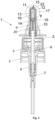
- Fig. 1 shows an embodiment of a dispensing device 1 for dispensing a fluid, preferably in spray form.
- the dispensing device 1 has a head base part 2, which is arranged on a snap-on 3.
- the head base part 2 is provided with a removable closure cap 4, which during the Use of the dispenser 1 can be removed from it (see Fig. 3 to 6 ).
- a cone 5 extends from the head base part 2 in an axial direction through the snap-on 3 into a housing 6.
- the cone 5 interacts with a housing spring 7 in the housing 6.
- the cone 5 has a fluid channel 8.
- the fluid channel 8 extends in the axial direction towards the head base part 2.
- the fluid channel 8 continues in the head base part 2 in a liner channel 9.
- This liner channel 9 is arranged between the head base part 2 and a liner 10.
- the liner 10 is formed in one piece.
- the liner 10 is supported on the head base part 2.
- the liner 10 also has an opening 11, through which the liner channel 9 opens into a valve chamber 12.
- the dispensing device 1 has a valve element 13 which is movably arranged in the liner 10. In the first position of the valve element 13 shown here, the valve element 13 is pressed against a dispensing opening 15 by a head spring 14. The dispensing opening 15 is thus closed by the valve element 13.
- the dispensing opening 15 is better positioned in the Fig. 2 , 4 , 5 and 6 and is described in more detail below.
- the valve element 13 has a sealing lip 16 which rests against an inner wall 17 of the liner 10. At an end of the valve element 13 opposite the sealing lip 16, the valve element 13 has a hemispherical closure surface 18 which also fits better into the Fig. 2 , 4 , 5 and 6 and will be described in more detail below. In the first position of the valve element 13, the closure surface 18 presses against the discharge opening 15 and closes it.
- the sealing lip 16 spatially separates an area of the valve chamber 12 from another area. This further area, in which the head spring 14 is arranged is called spring chamber 19.
- the liner 10 On the end opposite the valve element 13, the liner 10 has a plug 20 which is inserted into the liner 10. The plug 20 forms a contact surface of the head spring 14 and at the same time the transition between the fluid channel 8 and the liner channel 9.
- valve element 13 and the liner 10 also seal against each other.
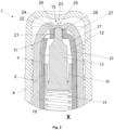
- This seal is indicated with the reference number 21, for example in Fig. 2 , wherein the seal 21 can be changed locally due to the different positions of the valve element 13 and does not require any explicit component design. Rather, the seal 21 is made as in Fig. 2 shown, by a surface pressure. Furthermore, the seal 21 separates the valve chamber 12 from the nozzle chamber 22.
- a hemispherical closure surface 23 of the valve element 13 rests against a cone 24 of the discharge opening 15
- the cone 24 has the shape of a truncated cone.
- a better representation of the nozzle chamber 22 and the cone 24 is particularly shown in FIG. Fig. 4 to 6 removable.
- Fig. 2 is a detailed view of the front area of the dispenser 1 of the Fig. 1 shown, ie, section X.
- the spherical closure surface 23 of the valve element 13 in the first position rests against the cone 24 in such a way that the closure surface 23 partially protrudes into a passage 25 of the discharge opening. This means that the closure surface 23 partially protrudes over the truncated cone, ie over the cover surface of the truncated cone, and protrudes into the passage 25.
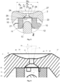
- the cylindrical passage 25 has a passage diameter D 1 , which is better in Fig. 5
- D 1 is between 0.2 and 0.6 mm.
- a diameter of 0.3 mm is particularly preferred.
- the passage 25 opens into a recess with a radius surface 26.
- the radius R R of the radius surface 26 is larger than the radius R K of the base surface of the cone 24, which is opposite the cover surface of the cone 24, and the cover surface forms the transition from the cone 24 to the passage 25.
- R R is 3 mm and R K is 0.5 mm.
- the radius of the passage 25 is smaller than the radius of the radius surface 26 and the base surface of the cone 24 and corresponds to the radius of the cover surface of the cone 24.
- the width of the radius surface W K in the illustration shown is approximately 2.65 mm.
- the cone has a cone angle ⁇ of approximately 120°.
- the cone angle ⁇ is in the range of 100° to 140°.
- the radius R R of the radius surface 26, the radius R K of the base surface of the cone 24, the width of the radius surface W K and the cone angle ⁇ are in the Fig. 5
- a spray angle ⁇ is also shown in Fig. 6 shown.
- the radius surface 26 forms a section of the outer contour 27 of the head base part 2, wherein due to the radius surface 26 designed as a recess, the opening of the passage 25 on the side of the radius surface 26 lies behind a front region of the head base part 2.
- Fig. 2 in some areas a channel 28 that bypasses the seal 21 and opens into the nozzle chamber 22.
- a fluid can thus flow through the channel 28 from the valve chamber 12 into the nozzle chamber 22.
- the channel thus represents the only fluid connection between the valve chamber 12 and the nozzle chamber 22. The fluid flow from the valve chamber 12 to the nozzle chamber 22 thus takes place past the seal 21.
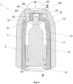
- Fig. 3 The dispenser 1, which is already in the Fig. 1 and 2 shown in a second position of the valve element 13, wherein the Closure cap 4 has been removed from the dispensing device 1.
- the valve element 13 In the second position of the valve element 13, the valve element 13 is displaced axially away from the dispensing opening 15 against the spring force of the head spring 14. This can be due to a fluid accumulation in the valve chamber 12, which exerts a fluid pressure on the sealing lip 16 and moves the valve element. Due to the movement of the valve element 13, both the volume of the valve chamber 12 and the volume of the nozzle chamber 22 are increased compared to the first position of the valve element 13.
- a channel opening 29 of the channel 28 is released due to the movement of the valve element 13 from the first position to the second position.
- a fluid which is under pressure in the valve chamber 12 can flow tangentially into the nozzle chamber 22 through the channel 28, which in this case is a vortex channel.
- FIG. 6 An example fluid flow is shown with solid arrows in Fig. 6 , the fluid entering the nozzle chamber 22 from the channel opening 29 initially flows in a rotational movement through the nozzle chamber 22 to the cone 24. With the help of the cone 24, the rotational movement of the fluid is converted into an axial movement, ie essentially into a movement parallel to an axis x 1 , which simultaneously forms the longitudinal axis of the dispensing device 1. The fluid is accelerated in the passage 25 and forms a spray cone 30 with a spray angle ⁇ when it exits.
- the spray cone 30 is shown by way of example with dashed lines for a better understanding of the invention. When the dispensing device is used, the spray cone 30 is formed by fluid drops.
- Fig. 1 and 2 represent a state of the dispensing device 1 in which the valve element 13 is arranged in a closed state, ie in a first position.
- Fig. 3 to 6 the same dispensing device 1 is shown without closure cap 4, in an open state, ie in a state in which the valve element 13 is in a second position.
- a user moves the head base part 2 in the axial direction towards the snap-on 3 after the closure cap 4 has been removed from the dispensing device 1.
- This causes the cone 5 inside the housing 6 to move against the spring force of the housing spring 7.
- This reduces the volume in a pump chamber of the housing 6.
- the pump chamber is formed by a space surrounding the housing spring 7.
- the amount of fluid delivered is determined by a stroke of the cone 5 within the pump chamber. This enables the dosing of a predetermined amount of fluid.
- the resulting overpressure displaces the fluid from the pump chamber into the fluid channel 8.
- the fluid is transported in an axial direction along the fluid channel 8.
- the transport of the fluid continues along the liner 10 through the liner channel 9. At one axial end of the liner channel 9, the fluid finally passes through the opening 11 and reaches the valve chamber 12.
- valve element 13 In the embodiment shown here, a certain amount of fluid accumulates in the valve chamber 12.
- the valve element 13 As long as the force applied to the valve element 13 by the fluid pressure is smaller than the force applied to the valve element 13 by the head spring 14, the valve element 13 is in the first position and lies with its hemispherical closure surface 23 on the cone 24 and closes the discharge opening 15, ie, the passage 25 in the direction of the radius surface 26.
- the valve element 13 closes with its outer surface the channel opening 29 of the channel 28, which connects the valve chamber 12 past the seal 21 with the nozzle chamber 22.
- valve chamber 12 As soon as the pressure in the valve chamber 12 is high enough to displace the valve element 13, it moves longitudinally within the liner 10 into a second position.
- This second position can be defined by a stop, which is not shown, so that the valve element 13 is moved until it hits a stop.
- the fluid presses through the channel 28 and through the outlet opening of the channel, i.e. the channel opening 29, into the nozzle chamber 22.
- the smaller cross-section of the channel 28 accelerates the fluid.
- the use of a vortex channel also ensures swirling of the fluid, which enters the nozzle chamber 22 tangentially.
- valve element 13 During the movement of the valve element 13 from the first to the second position, the volumes of the nozzle chamber 22 and the valve chamber 12 increase. However, the valve element 13 and the liner 10 continue to seal against each other.
- the sealing can be achieved, for example, by means of a surface pressure, which is identified in the figures with the reference number 21.
- the fluid flows in a rotational movement through the nozzle chamber 22 in the direction of the discharge opening 15.
- the cone 24 ensures that the rotational movement of the fluid is converted into an axial movement, so that the fluid is guided through the passage 25 essentially parallel to the axis x 1 .
- the fluid then exits the passage 25, thereby generating the spray mist formed from drops in the form of a spray cone 30.
- the spray cone initially has the spray angle ⁇ , wherein the angle ⁇ is preferably between 15° and 70°. Particularly preferably, ⁇ is between 30° and 45°.
- the pressure within the valve chamber 12 decreases during the fluid discharge through the discharge opening 15, provided no further fluid flows into the valve chamber 12. Consequently, the force acting on the sealing lip 16 also decreases as fluid continues to exit the discharge opening 15 of the dispensing device 1.
- valve element 13 is back in the first position and thus closes the discharge opening 15 until, for example, a liquid is pumped into the valve chamber 12 again and the pressure in the valve chamber 12 increases again.
- the embodiment according to the invention thus allows a continuous, sustained and permanent seal 21 between liner 10 and valve element 13, which is maintained independently of its movement, while at the same time a fluid can be discharged in the form of a spray from the discharge opening 15 in the second position of the valve element 13.
- the invention thus allows the combination of a sealed pressure chamber 22, a valve chamber 12, which allows pressure to build up, and a nozzle, which is formed from a nozzle chamber 22 and a discharge opening 15, so that a fluid can be sprayed out in spray form, using fewer components and a simple structural design. Due to this simple design of the discharge device 1, the discharge device 1 can be produced particularly inexpensively and is reliable and less prone to errors.
Landscapes
- Containers And Packaging Bodies Having A Special Means To Remove Contents (AREA)
Priority Applications (2)
| Application Number | Priority Date | Filing Date | Title |
|---|---|---|---|
| EP23188135.0A EP4497508A1 (fr) | 2023-07-27 | 2023-07-27 | Dispositif de distribution de fluide |
| US18/785,259 US20250033072A1 (en) | 2023-07-27 | 2024-07-26 | Dispensing device for a fluid |
Applications Claiming Priority (1)
| Application Number | Priority Date | Filing Date | Title |
|---|---|---|---|
| EP23188135.0A EP4497508A1 (fr) | 2023-07-27 | 2023-07-27 | Dispositif de distribution de fluide |
Publications (1)
| Publication Number | Publication Date |
|---|---|
| EP4497508A1 true EP4497508A1 (fr) | 2025-01-29 |
Family
ID=87517345
Family Applications (1)
| Application Number | Title | Priority Date | Filing Date |
|---|---|---|---|
| EP23188135.0A Pending EP4497508A1 (fr) | 2023-07-27 | 2023-07-27 | Dispositif de distribution de fluide |
Country Status (2)
| Country | Link |
|---|---|
| US (1) | US20250033072A1 (fr) |
| EP (1) | EP4497508A1 (fr) |
Citations (4)
| Publication number | Priority date | Publication date | Assignee | Title |
|---|---|---|---|---|
| US5558258A (en) * | 1994-05-25 | 1996-09-24 | Ter S.R.L. | Dispenser for dispensing atomized fluids under pressure, provided with a shut-off element operated by the pressurized fluid |
| US5842616A (en) * | 1996-04-24 | 1998-12-01 | Ter S.R.L. | Atomized liquid dispenser applicable to manually operated pumps |
| US20120018538A1 (en) * | 2009-03-19 | 2012-01-26 | Lumson S.P.A. | Dispensing device for fluid substances |
| EP3072597A1 (fr) | 2015-03-26 | 2016-09-28 | Aero Pump GmbH | Dispositif de depot pour un fluide |
Family Cites Families (21)
| Publication number | Priority date | Publication date | Assignee | Title |
|---|---|---|---|---|
| US4182496A (en) * | 1977-12-16 | 1980-01-08 | Ethyl Products Company | Actuator button for fluid dispenser |
| US4821928A (en) * | 1987-09-25 | 1989-04-18 | Su Cheng Y | Moveable valve structure for perfume atomizers |
| FR2671329B1 (fr) * | 1991-01-07 | 1993-03-19 | Valois | Embout-poussoir a jets multiples et a fermeture. |
| US5273191A (en) * | 1991-08-20 | 1993-12-28 | Philip Meshberg | Dispensing head for a squeeze dispenser |
| US5197638A (en) * | 1991-10-30 | 1993-03-30 | Allergan, Inc. | Self sealing product delivery system |
| EP0688608A1 (fr) * | 1994-03-25 | 1995-12-27 | GUALA S.p.A. | Dispositif de pulvérisation pour des pompes actionnées à la main |
| IT1272904B (it) * | 1995-01-16 | 1997-07-01 | Elettro Plastica Spa | Pompetta per l'erogazione di liquidi nebulizzati |
| DE19627228A1 (de) * | 1996-07-05 | 1998-01-08 | Pfeiffer Erich Gmbh & Co Kg | Austragvorrichtung für Medien |
| FR2758801B1 (fr) * | 1997-01-27 | 1999-03-26 | Valois | Systeme d'obturation d'un dispositif de distribution de produit fluide |
| IT1294275B1 (it) * | 1997-07-24 | 1999-03-24 | Giovanni Albini | Pulsante per l'erogazione di fluidi attraverso un ugello mobile sul pulsante stesso |
| FR2792552B1 (fr) * | 1999-04-20 | 2002-04-19 | Valois Sa | Tete de pulverisation de produit fluide comportant un obturateur ameliore |
| FR2793425B1 (fr) * | 1999-05-10 | 2002-03-08 | Oreal | Tete de distribution et recipient ainsi equipe |
| US7048155B2 (en) * | 2001-11-30 | 2006-05-23 | Yoshino Kogyosho Co., Ltd. | Depression head for pump mechanism |
| DE10200593A1 (de) * | 2002-01-10 | 2003-07-31 | Aero Pump Gmbh | Betätigungskopf einer Saug-Druck-Pumpe zum Ausspritzen eines Produkts aus einem Behältnis |
| WO2003099706A1 (fr) * | 2002-05-23 | 2003-12-04 | Cohen, Ben, Z. | Pompe medicale de precision |
| DE102005043258A1 (de) * | 2004-09-14 | 2006-03-16 | Eric Schliemann | Vorrichtung zum dosierten Ausbringen eines Mediums |
| FR2887232B1 (fr) * | 2005-06-21 | 2010-11-05 | Rexam Dispensing Sys | Embout poussoir pour distributeur de produit liquide |
| WO2007086156A1 (fr) * | 2006-01-26 | 2007-08-02 | Mitani Valve Co., Ltd. | Mecanisme de vidange de contenu pour recipient de type pompe et produit de type pompe muni d'un mecanisme de vidange de contenu |
| FR2975021B1 (fr) * | 2011-05-11 | 2014-03-07 | Jacques Gerbron | Pompe de dosage et de distribution d'un produit liquide ou visqueux |
| IT201600115319A1 (it) * | 2016-11-15 | 2018-05-15 | Lumson Spa | Dispositivo di erogazione di una sostanza fluida |
| EP4497511B1 (fr) * | 2023-07-27 | 2026-02-11 | Aero Pump GmbH | Dispositif de distribution de fluide |
-
2023
- 2023-07-27 EP EP23188135.0A patent/EP4497508A1/fr active Pending
-
2024
- 2024-07-26 US US18/785,259 patent/US20250033072A1/en active Pending
Patent Citations (4)
| Publication number | Priority date | Publication date | Assignee | Title |
|---|---|---|---|---|
| US5558258A (en) * | 1994-05-25 | 1996-09-24 | Ter S.R.L. | Dispenser for dispensing atomized fluids under pressure, provided with a shut-off element operated by the pressurized fluid |
| US5842616A (en) * | 1996-04-24 | 1998-12-01 | Ter S.R.L. | Atomized liquid dispenser applicable to manually operated pumps |
| US20120018538A1 (en) * | 2009-03-19 | 2012-01-26 | Lumson S.P.A. | Dispensing device for fluid substances |
| EP3072597A1 (fr) | 2015-03-26 | 2016-09-28 | Aero Pump GmbH | Dispositif de depot pour un fluide |
Also Published As
| Publication number | Publication date |
|---|---|
| US20250033072A1 (en) | 2025-01-30 |
Similar Documents
| Publication | Publication Date | Title |
|---|---|---|
| EP3072597B1 (fr) | Dispositif de depot pour un fluide | |
| DE69803361T2 (de) | Vorrichtung zur abgabe vom fliessfähigen produkt mit verschlussvorrichtung | |
| DE69225409T2 (de) | Düsenanordnung für zerstäuber vom triggertyp | |
| DE2531919C3 (de) | Betätigungsvorrichtung für ein Aerosolventil | |
| EP1986789B1 (fr) | Dispositif de dosage dote d'un dispositif de pompage actionne a la main | |
| DE3339180A1 (de) | Wirkstoffspender | |
| EP1447140A2 (fr) | Dispositif de décharge pour produire manuellement un écoulement d'un volume donné | |
| WO1991016989A1 (fr) | Buse rotative pour un appareil de nettoyage a haute pression | |
| EP2428282A1 (fr) | Piston à cartouche | |
| EP1375011B1 (fr) | Appareil de dosage pour au moins un fluide | |
| DE3025725A1 (de) | Spruehventilanordnung | |
| EP0451615B1 (fr) | Dispositif pour décharger au moins un produit | |
| DE60208925T2 (de) | Abgabevorrichtung für medien | |
| EP0285551A2 (fr) | Buse d'injection pour matière thermoplastique | |
| DE10034393A1 (de) | Sicherheitsgurtaufroller mit einem in seine Gurtwelle integrierten Flüssigkeitsdämpfer | |
| DE8715785U1 (de) | Ventil | |
| DE3525591A1 (de) | Auslassventil fuer eine tropfbewaesserung | |
| EP0887112A2 (fr) | Distributeur de fluides | |
| EP4497511B1 (fr) | Dispositif de distribution de fluide | |
| EP4497508A1 (fr) | Dispositif de distribution de fluide | |
| EP0388651B1 (fr) | Dispositif pour décharger un fluide | |
| WO2010145889A1 (fr) | Cartouche à plusieurs constituants à usage unique | |
| EP3238637B1 (fr) | Instrument entraîné par gaz sous pression, en particulier instrument chirurgical | |
| EP4368227B1 (fr) | Distributeur de liquide pour application nasale et dispositif de pompage | |
| EP0370257A2 (fr) | Soupape, notamment pour dispositifs manuels de décharge |
Legal Events
| Date | Code | Title | Description |
|---|---|---|---|
| PUAI | Public reference made under article 153(3) epc to a published international application that has entered the european phase |
Free format text: ORIGINAL CODE: 0009012 |
|
| STAA | Information on the status of an ep patent application or granted ep patent |
Free format text: STATUS: REQUEST FOR EXAMINATION WAS MADE |
|
| 17P | Request for examination filed |
Effective date: 20240208 |
|
| AK | Designated contracting states |
Kind code of ref document: A1 Designated state(s): AL AT BE BG CH CY CZ DE DK EE ES FI FR GB GR HR HU IE IS IT LI LT LU LV MC ME MK MT NL NO PL PT RO RS SE SI SK SM TR |
|
| P01 | Opt-out of the competence of the unified patent court (upc) registered |
Free format text: CASE NUMBER: APP_15373/2025 Effective date: 20250328 |
|
| STAA | Information on the status of an ep patent application or granted ep patent |
Free format text: STATUS: EXAMINATION IS IN PROGRESS |
|
| 17Q | First examination report despatched |
Effective date: 20250716 |