EP4497518A1 - Procédé de fabrication d'un treillis métallique tressé à épaisseur en saillie et treillis métallique ainsi fabriqué - Google Patents
Procédé de fabrication d'un treillis métallique tressé à épaisseur en saillie et treillis métallique ainsi fabriqué Download PDFInfo
- Publication number
- EP4497518A1 EP4497518A1 EP23187715.0A EP23187715A EP4497518A1 EP 4497518 A1 EP4497518 A1 EP 4497518A1 EP 23187715 A EP23187715 A EP 23187715A EP 4497518 A1 EP4497518 A1 EP 4497518A1
- Authority
- EP
- European Patent Office
- Prior art keywords
- metal braided
- wires
- braided net
- intertwining
- metal
- Prior art date
- Legal status (The legal status is an assumption and is not a legal conclusion. Google has not performed a legal analysis and makes no representation as to the accuracy of the status listed.)
- Granted
Links
Images


Classifications
-
- B—PERFORMING OPERATIONS; TRANSPORTING
- B21—MECHANICAL METAL-WORKING WITHOUT ESSENTIALLY REMOVING MATERIAL; PUNCHING METAL
- B21F—WORKING OR PROCESSING OF METAL WIRE
- B21F27/00—Making wire network, i.e. wire nets
- B21F27/005—Wire network per se
-
- B—PERFORMING OPERATIONS; TRANSPORTING
- B21—MECHANICAL METAL-WORKING WITHOUT ESSENTIALLY REMOVING MATERIAL; PUNCHING METAL
- B21F—WORKING OR PROCESSING OF METAL WIRE
- B21F27/00—Making wire network, i.e. wire nets
- B21F27/02—Making wire network, i.e. wire nets without additional connecting elements or material at crossings, e.g. connected by knitting
- B21F27/06—Manufacturing on twister-gear machines
-
- B—PERFORMING OPERATIONS; TRANSPORTING
- B21—MECHANICAL METAL-WORKING WITHOUT ESSENTIALLY REMOVING MATERIAL; PUNCHING METAL
- B21F—WORKING OR PROCESSING OF METAL WIRE
- B21F27/00—Making wire network, i.e. wire nets
- B21F27/12—Making special types or portions of network by methods or means specially adapted therefor
-
- E—FIXED CONSTRUCTIONS
- E01—CONSTRUCTION OF ROADS, RAILWAYS, OR BRIDGES
- E01C—CONSTRUCTION OF, OR SURFACES FOR, ROADS, SPORTS GROUNDS, OR THE LIKE; MACHINES OR AUXILIARY TOOLS FOR CONSTRUCTION OR REPAIR
- E01C3/00—Foundations for pavings
- E01C3/06—Methods or arrangements for protecting foundations from destructive influences of moisture, frost or vibration
-
- E—FIXED CONSTRUCTIONS
- E02—HYDRAULIC ENGINEERING; FOUNDATIONS; SOIL SHIFTING
- E02D—FOUNDATIONS; EXCAVATIONS; EMBANKMENTS; UNDERGROUND OR UNDERWATER STRUCTURES
- E02D17/00—Excavations; Bordering of excavations; Making embankments
- E02D17/20—Securing of slopes or inclines
- E02D17/202—Securing of slopes or inclines with flexible securing means
-
- E—FIXED CONSTRUCTIONS
- E02—HYDRAULIC ENGINEERING; FOUNDATIONS; SOIL SHIFTING
- E02D—FOUNDATIONS; EXCAVATIONS; EMBANKMENTS; UNDERGROUND OR UNDERWATER STRUCTURES
- E02D3/00—Improving or preserving soil or rock, e.g. preserving permafrost soil
- E02D3/005—Soil-conditioning by mixing with fibrous materials, filaments, open mesh or the like
Definitions
- the present invention relates to a method of manufacturing a metal braided net with a protruding thickness and the metal braided net made thereby and, more particularly, to a method of manufacturing a metal braided net which can increase a thickness of shotcrete to increase the strength of the structure and a metal braided net made thereby.
- a layer of metal braided nets is disposed on the structure and cement mortar is then sprayed to form a structure with a sufficient strength, thereby avoiding the hillside, the side slope, etc. from sliding, collapsing, or cracking.
- a metal braided net formed by braiding metal wires is disposed on the hillside or the slope side, and cement mortar is sprayed onto the metal braided net. Since the metal braided net has a small thickness and is directly attached to the hillside or the side slope, the cement mortar cannot have a sufficient thickness. As a result, the strength of the structure is insufficient to avoid cracking and collapse.
- a ground structure made of concrete such as a road or a bridge
- metal braided nets formed by braiding metal wires are disposed on the ground
- spacer blocks are disposed between the metal braided nets and the ground to raise the metal braided nets and, thus, provide a larger spacing between the metal braided nets and the ground. Therefore, the cement mortar can be fully filled between the metal braided nets and between the metal braided nets and the ground.
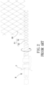
- a metal wire is bent to form plural rectilinear sections 91 of a specific length and plural V-shaped sections 92 of a specific length.
- the rectilinear sections 91 of plural metal wires are disposed in parallel at regular spacings, with an end of each V-shaped section 92 connected to an end of an adjacent rectilinear section 91 to form a connecting bent portion 93, and with another V-shaped section 92 protruding from a side of the V-shaped section 92, thereby forming a metal braided net 9.
- the above metal braided net 9 is produced by a conventional rhombic net producing method. Specifically, a metal wire P is wound around a mold M which rotates continuously and delivers the metal wire P , thereby forming a metal wire product P1 having the rectilinear sections 91 and the V-shaped sections 92 and having a specific length. The metal wire product P1 is braided into a metal braided net 9 produced by the same method. Since the metal wires P have to be wound around the mold M when producing the metal braided net 9, the metal braided net 9 can only be produced from metal wires P of a small diameter, and adjacent metal wire products P1 forming the metal braided net 9 can only be hooked together by the connecting bent portions 93. As a result, the metal braided net 9 has insufficient strength and, thus, cannot withstand a larger pressure. Furthermore, the metal braided net 9 will be damaged in a large area even only one metal wire product P1 is broken.
- the method can manufacture a metal braided net with protrusions to provide the metal braided net with a larger thickness.
- the term "a”, “an” or “one” for describing the number of the elements and members of the present invention is used for convenience, provides the general meaning of the scope of the present invention, and should be interpreted to include one or at least one. Furthermore, unless explicitly indicated otherwise, the concept of a single component also includes the case of plural components.
- a method of manufacturing a metal braided net with a protruding thickness includes: arranging a plurality of wires to form a plurality of pairs of wires contiguous to each other; proceeding with an intertwining step to intertwine each pair of wires contiguous to each other a predetermined number of turns to form an intertwining portion; proceeding with a displacement step to make each pair of wires contiguous to each other to displace relative to each other through a predetermined distance, where after an end of each of the plurality of wires has formed an inclining portion, plural pairs of contiguous metal wires are formed; repeating the intertwining step and the displacement step to form a metal braided net which has hexagonal meshes and a predetermined size; and forming a bending portion on each of the plurality of wires forming the metal braided net, with the bending portion protruding outward from at least one of an upper surface and a lower surface of the metal braided net.
- a metal braided net according to the present invention includes a plurality of wires and a plurality of bending portions.
- the plurality of wires is intertwined with each other to form a plurality of intertwining portions.
- the metal braided net has an upper surface and a lower surface opposite to the upper surface.
- the plurality of bending portions is formed on the plurality of wires. The plurality of bending portions protrudes from at least one of the upper surface and the lower surface of the metal braided net.
- the meshes of the metal braided net can include the intertwining portions to increase the structural strength of the metal braided net per se. Furthermore, by the bending step, the bending portions protrude from at least one of the upper surface and the lower surface of the metal braided net to thereby produce a metal braided net with a protruding thickness. Therefore, by provision of the bending portions on the metal braided net, a larger distance can be provided between the metal braided net and a plane of a hillside, a side slope, a road, or a bridge.
- the cement mortar when cement mortar is sprayed onto the metal braided net, the cement mortar can accumulate on the upper and lower sides of the wires. As a result, the cement mortar can form a larger thickness to increase the strength of the structure. Furthermore, the labor required for disposition of spacer blocks during construction may be reduced, thereby reducing the construction costs.
- the plurality of bending portions may be directly formed on the plurality of wires by at least one of pressing and bending.
- the bending portion can be formed easily.
- each of the plurality of bending portions may be formed between two adjacent intertwining portions.
- the bending portion can be formed easily.
- the plurality of bending portions may be formed on the intertwining portions.
- the bending portion abuts a plane, a better strength for supporting the metal braided net can be obtained.
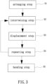
- a method of manufacturing a metal braided net with a protruding thickness of a preferred embodiment according to the present invention includes an arranging step S1, an intertwining step S2, a displacement step S3, a repeating step S4, and a bending step S5.
- the arranging step S 1 includes arranging a plurality of wires 1 to form a plurality of pairs of wires 1 contiguous to each other.
- the intertwining step S2 includes intertwining each pair of wires 1 contiguous to each other a predetermined number of turns.
- the displacement step S3 includes displace each pair of wires 1 contiguous to each other through a predetermined distance.
- the repeating step S4 includes repeating the intertwining step S2 and the displacement step S3 to form a metal braided net which has hexagonal meshes and has a predetermined size.
- the bending step S5 includes forming at least one bending portion 2 on the metal braided net.
- each wire 1 may be fixed to a tracking member L .
- Each wire 1 may be fixed to the tracking member L by tying, winding, or hooking.
- the tracking member L may be a reel and may be driven by a motor to continuously rotate in a direction. Therefore, the tracking member L may coil the metal braided net around the periphery of the tracking member L .
- a user may adjust the quantity of the wires 1 to form a metal braided net of a predetermined size.
- the present invention is not limited in this regard.
- a group of four wires 1a, 1b, 1c, 1d will be described as an example.
- the wires 1a, 1b, 1c, 1d are respectively positioned by four holding members T1, T2, T3, T4 of the braiding machine T .
- Two holding members T1 and T2 are contiguous to each other, such that the two wires 1a and 1b are contiguous to each other, whereas the other two holding members T3 and T4 are contiguous to each other, such that the other two wires 1c and 1d are contiguous to each other.
- the two holding members T1 and T2 rotate about an axis O1 between the two holding members T1 and T2 contiguous to each other, thereby intertwining the two wires 1a and 1b, whereas the other two holding members T3 and T4 rotate about another axis 02 between the other two holding members T3 and T4 contiguous to each other, thereby intertwining the other two wires 1c and 1d.
- the two holding members T1 and T2 may intertwine 3-4 turns, such that the two wires 1a and 1b form an intertwining portion 11.
- the other two holding members T3 and T4 may intertwine 3-4 turns, such that the other two wires 1c and 1d form an intertwining portion 11.
- the tracking member L may rotate at the same time to deliver the wires 1 to thereby proceed with coiling smoothly.
- the two holding members T1 and T2 move away from each other (namely, the two holding members T1 and T2 move leftward and rightward, respectively) through a predetermined distance and are, thus, separate from each other.
- the two wires 1a and 1b contiguous to each other are moved leftward and rightward respectively and, thus separate from each other, such that the wire 1a extends leftward and downward from an end of the associated intertwining portion 11 to form an inclined section, whereas the wire 1b extends rightward and downward from an end of the associated intertwining portion 11 to form an inclined section.
- the two holding members T3 and T4 move away from each other through the predetermined distance and are, thus, separate from each other.
- the two wires 1c and 1d contiguous to each other are moved leftward and rightward respectively and, thus separate from each other, such that the wire 1c extends leftward and downward from an end of the associated intertwining portion 11 to form an inclined section, whereas the wire 1d extends rightward and downward from an end of the associated intertwining portion 11 to form an inclined section.
- the holding member T2 that moves rightward will become contiguous to the holding member T3 that moves leftward, such that the two wires 1b and 1c become contiguous to each other.
- the wire 1a of this group and an adjacent wire on the left side of this group become contiguous to each other under actuation by the associated holding member T1 and the holding member on the left side thereof, whereas the wire 1d of this group and an adjacent wire on the right side of this group become contiguous to each other under actuation by the associated holding members T4 and the holding member on the right side thereof, which can be appreciated by one having ordinary skill in the art, and detailed description is not set forth to avoid redundancy.
- the above intertwining step S2 and the above displacement step S3 are repeated. Specifically, when the intertwining step S2 is repeated, the holding members T2 and T3 contiguous to each other rotate about an axis O3 between the holding members T2 and T3, such that the wires 1b and 1c intertwine to form an intertwining portion 11. At the same time, each of the wire 1a and the wire 1d is actuated by an associated holding member T1, T4 to intertwine with an adjacent wire to form an intertwining portion 11. When the displacement step S3 is repeated, the holding members T2 and T3 are moved away from each other (leftward and rightward respectively) through a predetermined distance and, thus, separate from each other.
- the wires 1b and 1c contiguous to each other are respectively moved leftward and rightward and, thus, separate from each other, such that the wire 1b extends leftward and downward from an end of the associated intertwining portion 11 to form an inclined section 12, whereas the wire 1c extends rightward and downward from an end of the associated intertwining portion 11 to form an inclined section 12.
- the holding member T1 actuates the wire 1a to intertwine with an adjacent wire on the left side and is then displaced again to become contiguous to the holding member T2 again
- the holding member T4 actuates the wire 1d to intertwine with an adjacent wire on the right side and is then displaced again to become contiguous to the holding member T3 again. Therefore, the holding members T1 and T2 are contiguous to each other again, whereas the holding members T3 and T4 are contiguous to each other again.
- a metal braided net having hexagonal meshes and a predetermined size may be obtained by repeating the intertwining step S2 and the displacement step S3 predetermined times.
- each hexagonal mesh of the metal braided net at least two opposite sides opposite to each other may form the intertwining portions 11 to reinforce the structure of the metal braided net.
- the structural integrity of the metal braided net can still be maintained.
- a mold may be used to directly form the bending portions 2 on the plurality of wires 1 by pressing or bending, such that the bending portions 2 may protrude outward from at least one of the upper surface and the lower surface of the metal braided net.
- the method of manufacturing a metal braided net with a protruding thickness according to the present invention can be used to produce a metal braded net from the plurality of wires 1.
- the metal braided net has an upper surface and a lower surface opposite to the upper surface.
- the plurality of wires 1 has a plurality of intertwining portions 11. At least one of the plurality of wires 1 has at least one bending portion 2.
- the bending portions 2 may protrude from at least one of the upper surface and the lower surface of the metal braided net. Thus, the bending portions 2 may abut a plane P to provide a larger distance between the metal braided net and the plane P .
- the protrusions of the bending portions 2 may be disposed regularly or irregularly, and each bending portion 2 may be formed between two adjacent intertwining portions 11. Alternatively, the bending portions 2 may be formed on the intertwining portions 11.
- the present invention is not limited in this regard. In this embodiment, the bending portions 2 protrude outward regularly from the lower surface of the metal braided net, and each bending portion 2 is formed between two adjacent intertwining portions 11.
- the metal braided net is disposed on a plane P of a hillside, a side slope, a road, or a bridge, due to provision of the bending portions 2, a larger distance is provided between the metal braided net and the plane P . Therefore, when cement mortar is sprayed on the metal braided net formed by the plurality of wires 1, the cement mortar may accumulate on the upper side of the plurality of wires 1 as well as the lower side of the plurality of wires 1. Thus, the cement mortar may form a larger thickness to increase the strength of the structure. Furthermore, the labor required for disposition of spacer blocks during construction may be reduced, thereby reducing the construction costs.
- FIGS. 8 and 9 showing a metal braided net of a second embodiment according to the present invention.
- the plurality of wires 1 has a plurality of bending portions 2.
- the bending portions 2 are spaced from each other and protrude outward from the lower surface of the metal braided net. Furthermore, the bending portions 2 are formed on the intertwining portions 11.
- FIGS. 10 and 11 showing a metal braided net of a third embodiment according to the present invention.
- This embodiment is generally the same as the second embodiment.
- the bending portions 2 are spaced from each other and protrude outward from the upper and lower surfaces of the metal braided net. Furthermore, the bending portions 2 are formed on the intertwining portions 11. Therefore, when cement mortar is poured, the cement mortar may form a larger thickness to increase the strength of the structure.
- the meshes of the metal braided net can include the intertwining portions to increase the structural strength of the metal braided net per se. Furthermore, by the bending step, the bending portions protrude from at least one of the upper surface and the lower surface of the metal braided net to thereby produce a metal braided net with a protruding thickness.
- a larger distance can be provided between the metal braided net and a plane of a hillside, a side slope, a road, or a bridge.
- cement mortar when cement mortar is sprayed onto the metal braided net, the cement mortar can accumulate on the upper and lower sides of the wires. As a result, the cement mortar can form a larger thickness to increase the strength of the structure. Furthermore, the labor required for disposition of spacer blocks during construction may be reduced, thereby reducing the construction costs.
Landscapes
- Engineering & Computer Science (AREA)
- Mechanical Engineering (AREA)
- Structural Engineering (AREA)
- Civil Engineering (AREA)
- Mining & Mineral Resources (AREA)
- Life Sciences & Earth Sciences (AREA)
- General Life Sciences & Earth Sciences (AREA)
- Paleontology (AREA)
- General Engineering & Computer Science (AREA)
- Architecture (AREA)
- Manufacturing & Machinery (AREA)
- Textile Engineering (AREA)
- Wire Processing (AREA)
Priority Applications (1)
| Application Number | Priority Date | Filing Date | Title |
|---|---|---|---|
| EP23187715.0A EP4497518B1 (fr) | 2023-07-25 | 2023-07-25 | Procédé de fabrication d'un treillis métallique tressé à épaisseur en saillie et treillis métallique ainsi fabriqué |
Applications Claiming Priority (1)
| Application Number | Priority Date | Filing Date | Title |
|---|---|---|---|
| EP23187715.0A EP4497518B1 (fr) | 2023-07-25 | 2023-07-25 | Procédé de fabrication d'un treillis métallique tressé à épaisseur en saillie et treillis métallique ainsi fabriqué |
Publications (2)
| Publication Number | Publication Date |
|---|---|
| EP4497518A1 true EP4497518A1 (fr) | 2025-01-29 |
| EP4497518B1 EP4497518B1 (fr) | 2026-04-22 |
Family
ID=87474261
Family Applications (1)
| Application Number | Title | Priority Date | Filing Date |
|---|---|---|---|
| EP23187715.0A Active EP4497518B1 (fr) | 2023-07-25 | 2023-07-25 | Procédé de fabrication d'un treillis métallique tressé à épaisseur en saillie et treillis métallique ainsi fabriqué |
Country Status (1)
| Country | Link |
|---|---|
| EP (1) | EP4497518B1 (fr) |
Citations (4)
| Publication number | Priority date | Publication date | Assignee | Title |
|---|---|---|---|---|
| CN1282804C (zh) * | 2002-04-23 | 2006-11-01 | 六发株式会社 | 网体、该网体的制造方法及设备和使用该网体的笼体 |
| JP2009030261A (ja) | 2007-07-25 | 2009-02-12 | Asahi Senzai Kogyosho:Kk | 金網 |
| US8646491B2 (en) * | 2003-10-22 | 2014-02-11 | Officine Maccaferri S.P.A. | Protective wire net, a protective structure constructed with the net, and the use of the protective wire net for the construction of a protective structure |
| US20140116568A1 (en) * | 2011-06-23 | 2014-05-01 | Chung-Ping Chen | Net Knitting Method |
-
2023
- 2023-07-25 EP EP23187715.0A patent/EP4497518B1/fr active Active
Patent Citations (4)
| Publication number | Priority date | Publication date | Assignee | Title |
|---|---|---|---|---|
| CN1282804C (zh) * | 2002-04-23 | 2006-11-01 | 六发株式会社 | 网体、该网体的制造方法及设备和使用该网体的笼体 |
| US8646491B2 (en) * | 2003-10-22 | 2014-02-11 | Officine Maccaferri S.P.A. | Protective wire net, a protective structure constructed with the net, and the use of the protective wire net for the construction of a protective structure |
| JP2009030261A (ja) | 2007-07-25 | 2009-02-12 | Asahi Senzai Kogyosho:Kk | 金網 |
| US20140116568A1 (en) * | 2011-06-23 | 2014-05-01 | Chung-Ping Chen | Net Knitting Method |
Also Published As
| Publication number | Publication date |
|---|---|
| EP4497518B1 (fr) | 2026-04-22 |
Similar Documents
| Publication | Publication Date | Title |
|---|---|---|
| US4505621A (en) | Wire retaining wall apparatus and method for earthen formations | |
| EP4497518A1 (fr) | Procédé de fabrication d'un treillis métallique tressé à épaisseur en saillie et treillis métallique ainsi fabriqué | |
| MX2011003388A (es) | Mamposteria con banda de acero reforzado que tiene separadores. | |
| US20250033109A1 (en) | Method of manufacturing a metal braided net with a protruding thickness and metal braided net made thereby | |
| US9267259B2 (en) | Soil reinforcing element for a mechanically stabilized earth structure | |
| JP2012021321A (ja) | 角形蛇篭 | |
| CN102078910A (zh) | 安全网及其制作方法 | |
| JP6643272B2 (ja) | 布団篭及びこれを使用した擁壁並びに施工方法 | |
| JP7462627B2 (ja) | 粒状要素を封じ込めるためのデバイス | |
| JPH03180617A (ja) | 急勾配盛土 | |
| TWI852701B (zh) | 具凸出厚度之金屬編織網製造方法及其金屬編織網 | |
| JP5588216B2 (ja) | 更生管製管用補強材入り帯状部材の製造方法 | |
| JP7356735B2 (ja) | 籠枠ユニット、籠枠連結体及び籠枠積層体並びに擁壁構築方法 | |
| AU2008241376A1 (en) | Reinforcing of formations | |
| JP2000008378A (ja) | 法面構造およびその構築方法 | |
| WO2025020087A1 (fr) | Procédé de fabrication de teillis tissé métallique ayant une épaisseur saillante, et teillis tissé métallique | |
| JPH0235860Y2 (fr) | ||
| CN119368649A (zh) | 具有凸出厚度的金属编织网制造方法及金属编织网 | |
| JP2009121086A (ja) | 盛土補強構造、及び、盛土補強方法 | |
| JP5986967B2 (ja) | 分割された盛土構築用壁面材ユニット | |
| US20150132070A1 (en) | Mechanically stabilized earth system and method | |
| JPS6317543Y2 (fr) | ||
| JP7805592B2 (ja) | 環境保全資材、じゃかごおよび環境保全資材の施工方法 | |
| JP6485841B2 (ja) | 盛土構造及びその構築方法 | |
| JP7360335B2 (ja) | 鉄筋ユニット及び鉄筋ユニットの製造方法 |
Legal Events
| Date | Code | Title | Description |
|---|---|---|---|
| PUAI | Public reference made under article 153(3) epc to a published international application that has entered the european phase |
Free format text: ORIGINAL CODE: 0009012 |
|
| STAA | Information on the status of an ep patent application or granted ep patent |
Free format text: STATUS: THE APPLICATION HAS BEEN PUBLISHED |
|
| AK | Designated contracting states |
Kind code of ref document: A1 Designated state(s): AL AT BE BG CH CY CZ DE DK EE ES FI FR GB GR HR HU IE IS IT LI LT LU LV MC ME MK MT NL NO PL PT RO RS SE SI SK SM TR |
|
| STAA | Information on the status of an ep patent application or granted ep patent |
Free format text: STATUS: REQUEST FOR EXAMINATION WAS MADE |
|
| 17P | Request for examination filed |
Effective date: 20250728 |
|
| GRAP | Despatch of communication of intention to grant a patent |
Free format text: ORIGINAL CODE: EPIDOSNIGR1 |
|
| STAA | Information on the status of an ep patent application or granted ep patent |
Free format text: STATUS: GRANT OF PATENT IS INTENDED |
|
| INTG | Intention to grant announced |
Effective date: 20251222 |
|
| GRAS | Grant fee paid |
Free format text: ORIGINAL CODE: EPIDOSNIGR3 |
|
| GRAA | (expected) grant |
Free format text: ORIGINAL CODE: 0009210 |
|
| STAA | Information on the status of an ep patent application or granted ep patent |
Free format text: STATUS: THE PATENT HAS BEEN GRANTED |
|
| AK | Designated contracting states |
Kind code of ref document: B1 Designated state(s): AL AT BE BG CH CY CZ DE DK EE ES FI FR GB GR HR HU IE IS IT LI LT LU LV MC ME MK MT NL NO PL PT RO RS SE SI SK SM TR |
|
| REG | Reference to a national code |
Ref country code: CH Ref legal event code: F10 Free format text: ST27 STATUS EVENT CODE: U-0-0-F10-F00 (AS PROVIDED BY THE NATIONAL OFFICE) Effective date: 20260422 |