EP4497520A1 - System und verfahren zum dreidimensionalen drucken eines kollimators - Google Patents
System und verfahren zum dreidimensionalen drucken eines kollimators Download PDFInfo
- Publication number
- EP4497520A1 EP4497520A1 EP24187559.0A EP24187559A EP4497520A1 EP 4497520 A1 EP4497520 A1 EP 4497520A1 EP 24187559 A EP24187559 A EP 24187559A EP 4497520 A1 EP4497520 A1 EP 4497520A1
- Authority
- EP
- European Patent Office
- Prior art keywords
- vector
- printing
- septa
- wall section
- wall
- Prior art date
- Legal status (The legal status is an assumption and is not a legal conclusion. Google has not performed a legal analysis and makes no representation as to the accuracy of the status listed.)
- Pending
Links
Images



Classifications
-
- B—PERFORMING OPERATIONS; TRANSPORTING
- B29—WORKING OF PLASTICS; WORKING OF SUBSTANCES IN A PLASTIC STATE IN GENERAL
- B29C—SHAPING OR JOINING OF PLASTICS; SHAPING OF MATERIAL IN A PLASTIC STATE, NOT OTHERWISE PROVIDED FOR; AFTER-TREATMENT OF THE SHAPED PRODUCTS, e.g. REPAIRING
- B29C64/00—Additive manufacturing, i.e. manufacturing of three-dimensional [3D] objects by additive deposition, additive agglomeration or additive layering, e.g. by 3D printing, stereolithography or selective laser sintering
- B29C64/10—Processes of additive manufacturing
- B29C64/141—Processes of additive manufacturing using only solid materials
- B29C64/153—Processes of additive manufacturing using only solid materials using layers of powder being selectively joined, e.g. by selective laser sintering or melting
-
- B—PERFORMING OPERATIONS; TRANSPORTING
- B22—CASTING; POWDER METALLURGY
- B22F—WORKING METALLIC POWDER; MANUFACTURE OF ARTICLES FROM METALLIC POWDER; MAKING METALLIC POWDER; APPARATUS OR DEVICES SPECIALLY ADAPTED FOR METALLIC POWDER
- B22F12/00—Apparatus or devices specially adapted for additive manufacturing; Auxiliary means for additive manufacturing; Combinations of additive manufacturing apparatus or devices with other processing apparatus or devices
-
- B—PERFORMING OPERATIONS; TRANSPORTING
- B22—CASTING; POWDER METALLURGY
- B22F—WORKING METALLIC POWDER; MANUFACTURE OF ARTICLES FROM METALLIC POWDER; MAKING METALLIC POWDER; APPARATUS OR DEVICES SPECIALLY ADAPTED FOR METALLIC POWDER
- B22F10/00—Additive manufacturing of workpieces or articles from metallic powder
- B22F10/20—Direct sintering or melting
- B22F10/28—Powder bed fusion, e.g. selective laser melting [SLM] or electron beam melting [EBM]
-
- A—HUMAN NECESSITIES
- A61—MEDICAL OR VETERINARY SCIENCE; HYGIENE
- A61B—DIAGNOSIS; SURGERY; IDENTIFICATION
- A61B6/00—Apparatus or devices for radiation diagnosis; Apparatus or devices for radiation diagnosis combined with radiation therapy equipment
- A61B6/42—Arrangements for detecting radiation specially adapted for radiation diagnosis
- A61B6/4291—Arrangements for detecting radiation specially adapted for radiation diagnosis the detector being combined with a grid or grating
-
- B—PERFORMING OPERATIONS; TRANSPORTING
- B22—CASTING; POWDER METALLURGY
- B22F—WORKING METALLIC POWDER; MANUFACTURE OF ARTICLES FROM METALLIC POWDER; MAKING METALLIC POWDER; APPARATUS OR DEVICES SPECIALLY ADAPTED FOR METALLIC POWDER
- B22F10/00—Additive manufacturing of workpieces or articles from metallic powder
- B22F10/30—Process control
- B22F10/36—Process control of energy beam parameters
- B22F10/366—Scanning parameters, e.g. hatch distance or scanning strategy
-
- B—PERFORMING OPERATIONS; TRANSPORTING
- B22—CASTING; POWDER METALLURGY
- B22F—WORKING METALLIC POWDER; MANUFACTURE OF ARTICLES FROM METALLIC POWDER; MAKING METALLIC POWDER; APPARATUS OR DEVICES SPECIALLY ADAPTED FOR METALLIC POWDER
- B22F10/00—Additive manufacturing of workpieces or articles from metallic powder
- B22F10/30—Process control
- B22F10/38—Process control to achieve specific product aspects, e.g. surface smoothness, density, porosity or hollow structures
-
- B—PERFORMING OPERATIONS; TRANSPORTING
- B22—CASTING; POWDER METALLURGY
- B22F—WORKING METALLIC POWDER; MANUFACTURE OF ARTICLES FROM METALLIC POWDER; MAKING METALLIC POWDER; APPARATUS OR DEVICES SPECIALLY ADAPTED FOR METALLIC POWDER
- B22F3/00—Manufacture of workpieces or articles from metallic powder characterised by the manner of compacting or sintering; Apparatus specially adapted therefor ; Presses and furnaces
- B22F3/10—Sintering only
- B22F3/11—Making porous workpieces or articles
- B22F3/1103—Making porous workpieces or articles with particular physical characteristics
- B22F3/1115—Making porous workpieces or articles with particular physical characteristics comprising complex forms, e.g. honeycombs
-
- B—PERFORMING OPERATIONS; TRANSPORTING
- B22—CASTING; POWDER METALLURGY
- B22F—WORKING METALLIC POWDER; MANUFACTURE OF ARTICLES FROM METALLIC POWDER; MAKING METALLIC POWDER; APPARATUS OR DEVICES SPECIALLY ADAPTED FOR METALLIC POWDER
- B22F5/00—Manufacture of workpieces or articles from metallic powder characterised by the special shape of the product
-
- B—PERFORMING OPERATIONS; TRANSPORTING
- B22—CASTING; POWDER METALLURGY
- B22F—WORKING METALLIC POWDER; MANUFACTURE OF ARTICLES FROM METALLIC POWDER; MAKING METALLIC POWDER; APPARATUS OR DEVICES SPECIALLY ADAPTED FOR METALLIC POWDER
- B22F5/00—Manufacture of workpieces or articles from metallic powder characterised by the special shape of the product
- B22F5/10—Manufacture of workpieces or articles from metallic powder characterised by the special shape of the product of articles with cavities or holes, not otherwise provided for in the preceding subgroups
-
- B—PERFORMING OPERATIONS; TRANSPORTING
- B33—ADDITIVE MANUFACTURING TECHNOLOGY
- B33Y—ADDITIVE MANUFACTURING, i.e. MANUFACTURING OF THREE-DIMENSIONAL [3D] OBJECTS BY ADDITIVE DEPOSITION, ADDITIVE AGGLOMERATION OR ADDITIVE LAYERING, e.g. BY 3D PRINTING, STEREOLITHOGRAPHY OR SELECTIVE LASER SINTERING
- B33Y10/00—Processes of additive manufacturing
-
- B—PERFORMING OPERATIONS; TRANSPORTING
- B33—ADDITIVE MANUFACTURING TECHNOLOGY
- B33Y—ADDITIVE MANUFACTURING, i.e. MANUFACTURING OF THREE-DIMENSIONAL [3D] OBJECTS BY ADDITIVE DEPOSITION, ADDITIVE AGGLOMERATION OR ADDITIVE LAYERING, e.g. BY 3D PRINTING, STEREOLITHOGRAPHY OR SELECTIVE LASER SINTERING
- B33Y30/00—Apparatus for additive manufacturing; Details thereof or accessories therefor
-
- B—PERFORMING OPERATIONS; TRANSPORTING
- B33—ADDITIVE MANUFACTURING TECHNOLOGY
- B33Y—ADDITIVE MANUFACTURING, i.e. MANUFACTURING OF THREE-DIMENSIONAL [3D] OBJECTS BY ADDITIVE DEPOSITION, ADDITIVE AGGLOMERATION OR ADDITIVE LAYERING, e.g. BY 3D PRINTING, STEREOLITHOGRAPHY OR SELECTIVE LASER SINTERING
- B33Y50/00—Data acquisition or data processing for additive manufacturing
-
- B—PERFORMING OPERATIONS; TRANSPORTING
- B33—ADDITIVE MANUFACTURING TECHNOLOGY
- B33Y—ADDITIVE MANUFACTURING, i.e. MANUFACTURING OF THREE-DIMENSIONAL [3D] OBJECTS BY ADDITIVE DEPOSITION, ADDITIVE AGGLOMERATION OR ADDITIVE LAYERING, e.g. BY 3D PRINTING, STEREOLITHOGRAPHY OR SELECTIVE LASER SINTERING
- B33Y80/00—Products made by additive manufacturing
-
- G—PHYSICS
- G21—NUCLEAR PHYSICS; NUCLEAR ENGINEERING
- G21K—HANDLING OF PARTICLES OR IONISING RADIATION NOT OTHERWISE PROVIDED FOR; IRRADIATION DEVICES; GAMMA RAY OR X-RAY MICROSCOPES
- G21K1/00—Arrangements for handling particles or ionising radiation, e.g. focusing or moderating
- G21K1/02—Arrangements for handling particles or ionising radiation, e.g. focusing or moderating using diaphragms, collimators
- G21K1/025—Arrangements for handling particles or ionising radiation, e.g. focusing or moderating using diaphragms, collimators using multiple collimators, e.g. Bucky screens; other devices for eliminating undesired or dispersed radiation
Definitions
- the subject matter disclosed herein relates to three-dimensional (3D) printing of a collimator.
- Various mechanical and micro-mechanical systems may employ gratings or grids that include some form of trench or other opening defined at least partially by sidewalls (e.g., vertical sidewalls or septa). Such gratings or grids may be employed to limit or collimate the passage of energy or material from one side of the grating or grid to the opposite side or may perform other functions where the trench or other sidewall structures facilitate the functioning of the overall system.
- sidewalls e.g., vertical sidewalls or septa
- Additive manufacturing technologies are getting more popular for utilization in the industry environment.
- the manufacturability of multiple materials e.g., 316L, J13 Iconel 718, 625, AlSi10Mg, etc.
- refractory materials still pose a challenge especially for laser powder bed fusion (LPBF) technologies.
- LPBF laser powder bed fusion
- tungsten printing is a niche and limited industries are investing in it.
- manufacturing of a computed tomography (CT) collimator using 3D printing is challenging due to thin walls, close manufacturing tolerances, and utilization of tungsten material.
- Utilizing LPDF to make a 3D printed collimator needing multiple layers (for building thickness) currently produces an article with lower than acceptable density and rough surfaces that raise quality issues.
- a method for forming a metallic grid structure includes utilizing three-dimensional (3D) printing for printing a first layer of a first wall section of the metallic grid structure in a first direction along a first vector offset from a first center line of the first wall section by half of a first distance of a first width of the first wall section that is orthogonal to the first center line.
- the method also includes utilizing 3D printing for printing a second layer of the first wall section on the first layer in a second direction along a second vector offset from the first center line of the first wall section by half of the first distance of the first width of the first wall section, wherein the second direction is opposite the first direction, and the first vector and the second vector are disposed on opposite sides of the first center line.
- a method for forming a collimator configured for use with an X-ray detector of an X-ray imaging system includes utilizing three-dimensional (3D) printing for alternately printing layers of a first set of septa of the collimator extending in a first direction by alternating between utilizing a first vector and a second vector in printing the layers of the first set of septa, wherein the first vector and the second vector are oriented in opposite directions along the first direction, disposed on opposite sides of a first center line of a respective septa of the first set of septa, and offset from the first center line half of a first distance of a first width of the respective septa of the first set of septa.
- 3D three-dimensional
- the method also includes utilizing 3D printing for alternately printing layers of a second set of septa of the collimator extending in a second direction by alternating between utilizing a third vector and a fourth vector in printing the layers of the second set of septa, wherein the third vector and the fourth vector are oriented in opposite directions along the second direction and disposed on opposite sides of a second center line of a respective septa of the second set of septa, and offset from the second center line half of a second distance of a second width of the respective septa of the second set of septa, wherein the first direction is orthogonal to the second direction.
- a system for forming a collimator configured for use with an X-ray detector of an X-ray imaging system includes a memory encoding processor-executable routines.
- the system also includes processing circuitry configured to access the memory and to execute the processor-executable routines, wherein the routines, when executed by the processing circuitry, cause the processing circuitry to perform actions.
- the actions include utilizing three-dimensional (3D) printing for alternately printing layers of a first set of septa of the collimator extending in a first direction by alternating between utilizing a first vector and a second vector in printing the layers of the first set of septa, wherein the first vector and the second vector are oriented in opposite directions along the first direction, disposed on opposite sides of a first center line of a respective septa of the first set of septa, and offset from the first center line half of a first distance of a first width of the respective septa of the first set of septa.
- 3D three-dimensional
- the actions also include utilizing 3D printing for alternately printing layers of a second set of septa of the collimator extending in a second direction by alternating between utilizing a third vector and a fourth vector in printing the layers of the second set of septa, wherein the third vector and the fourth vector are oriented in opposite directions along the second direction and disposed on opposite sides of a second center line of a respective septa of the second set of septa, and offset from the second center line half of a second distance of a second width of the respective septa of the second set of septa, wherein the first direction is orthogonal to the second direction.
- CT Computed Tomography
- the present approaches may also be utilized in other contexts, such as tomographic image reconstruction for industrial Computed Tomography (CT) used in non-destructive inspection of manufactured parts or goods (i.e., quality control or quality review applications), and/or the non-invasive inspection of packages, boxes, luggage, and so forth (i.e., security or screening applications).
- CT Computed Tomography
- the present approaches may be useful in any imaging or screening context that utilizes X-ray imaging gratings such as collimator or anti-scatter grids.
- the present approaches may be utilized in any imaging system that utilizes a collimator or anti-scatter grid (e.g., conventional X-ray imaging system, positron emission tomography imaging, etc.).
- the present techniques relate to various aspects of additively manufacturing (e.g., three-dimensional (3D) printing of an X-ray grating or metallic grid structure (e.g., collimator or X-ray grid).
- the present techniques provide for a customized single vector zig-zag printing strategy (i.e., single vector per layer of a given wall or given wall section) that utilizes alternate vectors that are offset from a septa (e.g., wall) center by a half a vector distance in an opposite direction.
- 3D printing may be utilized to print a collimator (e.g., made of multiple layers) for use with an X-ray detector of an X-ray imaging system, wherein the 3D printing is utilized for alternately printing layers of a first set of septa of the collimator extending in a first direction by alternating between utilizing a first vector and a second vector in printing the layers of the first set of septa.
- the first and second vector are oriented in opposite directions along the first direction, disposed on opposite sides of a first center line of a respective septa of the first set of septa, and offset from the first center line half of first distance (e.g., vector distance) of a first width of the respective septa of the first set of septa.
- the 3D printing is also utilized for alternately printing layers of a second set of septa of the collimator extending in a second direction by alternating between utilizing a third vector and a fourth vector in printing the layers of the second set of septa.
- the third vector and the fourth vector are oriented in opposite directions along the second direction and disposed on opposite sides of a second center line of a respective septa of the second set of septa, and offset from the second center line half of a second distance of a second width of the respective septa of the second set of septa.
- the first direction is orthogonal to the second direction.
- the collimator This creates an article (i.e., the collimator) (where a conventional process would require a multi-vector strategy for a given thickness (i.e., greater than 100 micrometers)) having a smoother finish and a higher density.
- the disclosed techniques also improve productivity, unifies septa characteristics, and enables the printing of symmetrical walls.
- the disclosed techniques improve measurement capabilities when utilizing the collimator due to the use of backlight and the smoother finish which helps with edge detection. Further, the disclosed techniques reduce cleaning time and reduce/remove the appearance of residual particles stuck to the septa surface.
- FIG. 1 illustrates an embodiment of an imaging system 10 for acquiring and processing image data in accordance with structures and approaches discussed herein. That is, the depicted type of imaging system 10 is an example of one type of imaging system that may benefit from or otherwise utilize components made in accordance with the techniques described herein (e.g., multiple layer X-ray gratings such as an anti-scatter grid or collimator). Though, as noted herein, other types of systems (e.g., non-imaging systems, non-medical systems, and so forth) may also utilize components made in accordance with the techniques described herein.
- other types of systems e.g., non-imaging systems, non-medical systems, and so forth
- components made in accordance with the techniques described herein may also utilize components made in accordance with the techniques described herein.
- system 10 is a computed tomography (CT) system designed to acquire X-ray projection data and to reconstruct the projection data into volumetric reconstructions for display and analysis.
- CT imaging system 10 includes one or more X-ray sources 12, such as one or more X-ray tubes or solid state emission structures which allow X-ray generation at one or more energy spectra during an imaging session.
- the source 12 may be positioned proximate to a pre-patient collimator and/or filter assembly 22 that may be used to steer the X-ray beam 20, to define the shape (such as by limiting off-angle emissions) and/or extent of a high-intensity region of the X-ray beam 20, to control or define the energy profile of the X-ray beam 20, and/or to otherwise limit X-ray exposure on those portions of the patient 24 not within a region of interest.
- the filter assembly or beam shaper 22 may be incorporated within the gantry, between the source 12 and the imaged volume.
- the X-ray beam 20 passes into a region in which the subject (e.g., a patient 24) or object of interest (e.g., manufactured component, baggage, package, and so forth) is positioned.
- the subject attenuates at least a portion of the X-ray photons 20, resulting in attenuated X-ray photons 26 that impinge upon a pixelated detector array 28 formed by a plurality of detector elements (e.g., pixels) arranged in an array.
- the attenuated X-ray photons 26 pass through a collimator 18 (e.g., an anti-scatter grid) prior to reaching the detector array 28.
- a collimator 18 e.g., an anti-scatter grid
- the collimator 18 may consist of a plurality of blades or other elements aligned substantially perpendicular to the surface of the detector array 28 and formed from an attenuating material that limit or prevent X-ray photons 26 traveling at off-angles (e.g., scattered X-rays) from reaching the detector array 28.
- the electrical signals reaching the detector array 28 are detected and processed to generate one or more projection datasets.
- the detector 28 is coupled to the system controller 30, which commands acquisition of the digital signals generated by the detector 28.
- a system controller 30 commands operation of the imaging system 10 to execute filtration, examination and/or calibration protocols, and may process the acquired data.
- the system controller 30 furnishes power, focal spot location, control signals and so forth, for the X-ray examination sequences.
- the system controller 30 may control operation of the filter assembly 22, the CT gantry (or other structural support to which the X-ray source 12 and detector 28 are attached), and/or the translation and/or inclination of the patient support over the course of an examination.
- the radiation source 12 and detector 28 rotate about the object (e.g., patient 24) to acquire X-ray transmission data over a range of angular views.
- the imaging system 10 is configured to generate X-ray transmission data corresponding to each of the plurality of angular positions (e.g., 360°, 180° + a fan beam angle ( ⁇ ), and so forth) covering an entire scanning area of interest.
- the system controller 30 may include signal processing circuitry and associated memory circuitry.
- the memory circuitry may store programs, routines, and/or encoded algorithms executed by the system controller 30 to operate the imaging system 10, including the X-ray source 12 and/or filter assembly 22, and to process the digital measurements acquired by the detector 28.
- the system controller 30 may be implemented as all or part of a processor-based system.
- the source 12 may be controlled by an X-ray controller 38 contained within the system controller 30.
- the X-ray controller 38 may be configured to provide power, timing signals, and/or focal spot size and spot locations to the source 12.
- the X-ray controller 38 may be configured to selectively activate the source 12 such that tubes or emitters at different locations within the system 10 may be operated in synchrony with one another or independent of one another or to switch the source between different energy profiles during an imaging session.
- the system controller 30 may include a data acquisition system (DAS) 40.
- the DAS 40 receives data collected by readout electronics of the detector 28, such as digital signals from the detector 28.
- the DAS 40 may then convert and/or process the data for subsequent processing by a processor-based system, such as a computer 42.
- circuitry within the detector 28 may convert analog signals of the detector to digital signals prior to transmission to the data acquisition system 40.
- the computer 42 may include or communicate with one or more non-transitory memory devices 46 that can store data processed by the computer 42, data to be processed by the computer 42, or instructions to be executed by image processing circuitry 44 of the computer 42.
- a processor of the computer 42 may execute one or more sets of instructions stored on the memory 46, which may be a memory of the computer 42, a memory of the processor, firmware, or a similar instantiation.
- the image processing circuitry 44 of the computer 42 may be configured to generate a diagnostic image.
- the computer 42 may also be adapted to control features enabled by the system controller 30 (i.e., scanning operations and data acquisition), such as in response to commands and scanning parameters provided by an operator via an operator workstation 48.
- the system 10 may also include a display 50 coupled to the operator workstation 48 that allows the operator to view relevant system data, imaging parameters, raw imaging data, reconstructed data or images, and so forth.
- the system 10 may include a printer 52 coupled to the operator workstation 48 and configured to print any desired measurement results.
- the display 50 and the printer 52 may also be connected to the computer 42 directly (as shown in FIG. 1 ) or via the operator workstation 48.
- the operator workstation 48 may include or be coupled to a picture archiving and communications system (PACS) 54.
- PACS 54 may be coupled to a remote system or client 56, radiology department information system (RIS), hospital information system (HIS) or to an internal or external network, so that others at different locations can gain access to the image data.
- RIS radiology department information system
- HIS
- the detector 28 is shown as including an array of pixels 58 each corresponding to a readout channel.
- a set of collimator blades 60 of the collimator 18 are shown associated with the array of pixels 58 such that each pixel is separately collimated.
- the blades 60 are shown as being placed at where pixels are joined, such that shadowing attributable to the blades 60 is primarily at these joints, leaving the majority of the active area of the pixels 58 relatively free of shadows produced by the blades. In this manner, each pixel 58 is effected relatively consistently and uniformly by the collimator blades 60.
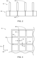
- FIG. 3 depicts a top view of a portion of the collimator 18 (e.g., metallic grid structure).
- the collimator 18 includes a first set 62 of septa 64 (e.g., walls) extending in a first direction 66.
- the collimator 18 also includes a second set 68 of septa 64 (e.g., walls) extending in a second direction 70 orthogonal to the first direction 66.
- Each septum 64 of both the first set 62 of septa 64 and the second set 68 of septa 64 has a width 72 (e.g., thickness) extending in the second direction 70 and the first direction 66, respectively.
- the width 72 is greater than 100 micrometers.
- the first set 62 of septa 64 and the second set 68 of septa 64 intersect or meet to form a joint or intersection 74.
- the collimator 18 in FIGS. 2 and 3 may be 3D printed and formed of multiple layers as described in greater detail below.
- the collimator 18 of FIGS. 2 and 3 may be made of tungsten.
- FIG. 4 depicts schematically a conventional printing strategy (e.g., utilizing a single vector) for printing a wall or septum of a collimator.
- vertical box 76 represents a wall or septum of a collimator that extends in a direction 80 (e.g., Y-direction).
- the wall or septum 76 includes a center line 78.
- the wall or septum 76 is 3D printed in multiple layers 82 with each layer 82 printed as a laser patch on top of the other layers 82 so that the wall or septum 76 extends in a direction 84 (e.g., Z-direction).
- Each layer 82 includes a layer thickness 86 (e.g., Lt) in the direction 84.
- the wall or septum 76 includes a width 88 (e.g., wall thickness) extending in a direction 90 (e.g., X-direction) orthogonal to the direction 80.
- the width 88 is 100 micrometers or less.
- the center line 78 is centrally located within the width 88.
- the individual layers 82 of the wall or septum 76 are printed as a single vector exposure 92 (e.g., with a thickness of 100 micrometers or less) in the direction 80.
- FIG. 5 depicts schematically a conventional printing strategy (e.g., utilizing a two vector strategy) for printing a wall or septum of a collimator.
- a vertical box 94 represents a portion of a wall or septum 96 of a collimator that extends in the direction 80 (e.g., Y-direction) printed utilizing a first vector exposure 98 (e.g., with a thickness of 100 micrometers or less).
- a vertical box 100 represent a portion of the wall or septum 96 printed utilizing a second vector exposure 102 (e.g., with a thickness greater than 100 micrometers).
- the wall or septum 96 includes a center line 104.
- the wall or septum 96 is 3D printed in multiple layers 82 with each layer 82 printed as a laser patch on top of the other layers 82 (of the same vector exposure) so that the wall or septum 96 extends in the direction 84 (e.g., Z-direction).
- Each layer 82 includes the layer thickness 86 (e.g., L t ) in the direction 84.
- the wall or septum 96 includes a width 106 (e.g., wall thickness) extending in the direction 90 (e.g., X-direction) orthogonal to the direction 80.
- the width 106 is greater than 140 micrometers.
- the center line 78 is centrally located within the width 106.
- the individual layers 82 of the wall or septum 96 are printed utilizing two adjacent vectors, the first vector exposure 98 in the direction 80 and the second vector exposure 102 in a direction 108 opposite the direction 80.
- the portion 94 of the wall or septum 96 is formed by printing layers 82 as a laser patch utilizing the first vector exposure 98 on top of each other to form the portion 94.
- the portion 100 of the wall or septum 96 is formed by printing layers 82 as a laser patch utilizing the second vector exposure 102 on top of each other to form the portion 100.
- each layer of the wall 96 is printed via the first vector exposure 98 and the second vector exposure 102.
- a vector distance 110 (e.g., L Dxy ) represents a distance along the direction 90 between the first vector exposure 98 and the second vector exposure 102.
- the printing strategy in FIG. 4 works well for printing walls or septa of a collimator that are smaller than 100 micrometers.
- a multi-vector strategy for printing individual layers
- FIG. 5 a multi-vector strategy (for printing individual layers) as depicted in FIG. 5 is utilized which leads to the following issues or problems.
- These issues include increased surface roughness and reduced wall density relative to design (desired) wall density.
- These issues also include asymmetrical wall characteristics (e.g., more roughness and less density in the second vector patch).
- These issues further include that measured wall thickness does not represent the designed wall thickness.
- residual particles on septa surfaces and porosity usually lead to thicker wall but a reduced density, all of which decreases collimator performance.
- These issues further even further include longer postprocessing (e.g., ultrasonic cleaning to remove particles loosely connected to the septa surfaces).
- FIG. 6 depicts schematically a zig-zag printing strategy (e.g., utilizing a single vector printing strategy) for printing a wall or septum 112 of a collimator or a section of the wall or septum 112.
- the wall or septum 112 of the collimator extends in the direction 80 (e.g., Y-direction).
- the wall or septum 112 includes a center line 114.
- the wall or septum 112 is 3D printed in multiple layers 116 with each layer 116 printed as a laser patch on top of the other layers 116 so that the wall or septum 112 extends in the direction 84 (e.g., Z-direction).
- Each layer 116 includes the layer thickness 86 (e.g., Lt) in the direction 84.
- the wall or septum 112 includes a width 118 (e.g., wall thickness) extending in the direction 90 (e.g., X-direction) orthogonal to the direction 80.
- the width 118 is greater than 100 micrometers.
- the center line 114 is centrally located within the width 118.
- the individual layers 116 of the wall or septum 112 are alternately printed utilizing two different vectors (e.g., with a single vector per layer 116).
- an initial layer 120 (layer n) is printed along a first vector 122 (V1) in a first direction (i.e., the Y-direction 80) utilizing the first vector exposure.
- the first vector 122 is offset from the center line 114 by half of a distance of the width 118 (or vector distance 136).
- the next layer 124 (layer n + 1) is printed along a second vector 126 (V2) as a laser patch on the initial layer 120 in a second direction 128 opposite the first direction 80 utilizing the second vector exposure.
- the second vector 126 is offset from the center line 114 by half of a distance of the width 118 (or vector distance 136).
- the first vector 122 and the second vector 126 are disposed on opposite sides 130, 132, respectively, of the center line 114.
- the layer 124 has the same thickness as the initial layer 120.
- the layers 120, 124 together have a layer thickness 134 (2xL t ).
- a vector distance 136 (e.g., L Dxy ) represents a distance along the direction 90 between the first vector 122 and the second vector 126.
- the vector distance 136 represents the distance in shifting between the first vector 122 and the second vector 126 to print the respective layers 116.
- the vector distance 136 is determined based on a combination of laser power and laser speed to achieve the expected printing result.
- vector distance 136 is the same as the width 118 of the wall 112.
- vectors of different directions may be utilized in printing a layer of a septum or wall to improve density and surface finish of a printed collimator.
- different vectors may be utilized for different (and adjacent) sections of the wall or septum on the same layer, where a single vector is utilized on each section of the wall or septum.
- the layers 116 are alternately printed by alternating between utilizing the first vector 122 and the second vector 126 for printing a respective layer 116.
- This alternating use of the first vector 122 and the second vector results in a zig-zag pattern 138 in the direction 84.
- the utilization of the zig-zag strategy improves productivity, improves collimator surface finish and improves wall density up to 99.9 percent (excluding cracks).
- the utilization of the zig-zag strategy also unifies septa characteristics and enables the printing of symmetrical walls.
- the utilization of the zig-zag strategy further provides measurement capability improvements (e.g., using backlight and a smoother surface finish helps with edge detection).
- the utilization of the zig-zag strategy further reduces cleaning time and reduces or removes the appearance of residual particles stuck to septa surfaces. In sum, the utilization of the zig-strategy enables faster printing with a better quality that meet critical to quality standards.
- FIGS. 7 and 8 illustrate the differences between collimators printed with conventional and customized zig-zag printing strategies.
- FIG. 7 depicts an image 140 from above of a portion of a collimator 142 printed utilizing the conventional printing strategy (e.g., two vector strategy in FIG. 5 ).
- FIG. 8 depicts an image 144 from above of a portion of collimator 146 printed utilizing the zig-zag printing strategy in FIG. 6 (and/or FIGS. 9 and/or 10).
- walls 148 of the collimator 142 have visible asymmetry.
- the walls 148 of the collimator 142 are rough and have density issues.
- walls 150 of the collimator 146 are more asymmetrical.
- the walls 150 are denser and smoother. Further, the walls 150 have fewer residual particles.
- the target wall thickness for both of the collimators 142, 146 was 150 micrometers.
- FIG. 9 depicts schematically a zig-zag printing strategy (e.g., utilizing alternate vectors printing strategy) for printing the wall or septum of a collimator.
- the wall or septum 112 of the collimator extends in the direction 80 (e.g., Y-direction).
- the wall or septum 112 is printed in two portions or sections 152 and 154. The portions 152 and 154 are printed adjacent to each other and are aligned in the direction 80.
- the printing of the portion 152 utilizes a zig-zag printing strategy alternating between two vectors in printing the layers of the portion 152.
- the printing of the portion 154 utilizes a zig-zag printing strategy alternating between the same two vectors (utilized in printing the portion 152) in printing the layers of the portion 154 but utilizing the two vectors in a different order.
- the wall or septum 112 includes the center line 114 for both portions 152 and 154.
- the portion 152 is 3D printed in multiple layers 116 with each layer 116 printed as a laser patch on top of the other layers 116 so that the portion 152 extends in the direction 84 (e.g., Z-direction).
- Each layer 116 includes the layer thickness 86 (e.g., Lt) in the direction 84.
- the portion 152 includes the width 118 (e.g., wall thickness) extending in the direction 90 (e.g., X-direction) orthogonal to the direction 80.
- the width 118 is greater than 100 micrometers.
- the center line 114 is centrally located within the width 118.
- the individual layers 116 of the portion 152 are alternately printed utilizing two different vectors (e.g., with a single vector per portion of the layer 116).
- the initial layer 120 (layer n) of the portion 152 is printed along the first vector 122 (V1) in the first direction (i.e., the Y-direction 80) utilizing the first vector exposure.
- the first vector 122 is offset from the center line 114 by half of a distance of the width 118 (or vector distance 136).
- the next layer 124 (layer n + 1) of the portion 152 is printed along the second vector 126 (V2) as a laser patch on the initial layer 120 in the second direction 128 opposite the first direction 80 utilizing the second vector exposure.
- the second vector 126 is offset from the center line 114 by half of a distance of the width 118 (or vector distance 136).
- the first vector 122 and the second vector 126 are disposed on opposite sides 130, 132, respectively, of the center line 114 in printing the portion 152.
- the layer 124 has the same thickness as the initial layer 120.
- the layers 120, 124 of the portion 152 together have a layer thickness 134 (2xL t ).
- the vector distance 136 (e.g., L Dxy ) represents a distance along the direction 90 between the first vector 122 and the second vector 126.
- the vector distance 136 represents the distance in shifting between the first vector 122 and the second vector 126 to print the respective layers 116 of the portion 152.
- the vector distance 136 is determined based on a combination of laser power and laser speed to achieve the expected printing result. In this case, the vector distance 136 is the same as the width 118 of the wall 112.
- the portion 154 is 3D printed in multiple layers 116 (corresponding to same layers 116 in the portion 152) with each layer 116 printed as a laser patch on top of the other layers 116 so that the portion 154 extends in the direction 84 (e.g., Z-direction).
- Each layer 116 of the portion 154 also includes the same layer thickness 86 (e.g., Lt) in the direction 84.
- the portion 154 includes the same width 118 (e.g., wall thickness) as the portion 152 extending in the direction 90 (e.g., X-direction) orthogonal to the direction 80.
- the individual layers 116 of the portion 154 are alternately printed utilizing the same two different vectors (e.g., with a single vector per portion of the layer 116) utilized in printing the portion 152.
- the initial layer 120 (layer n) of the portion 154 is printed along the second vector 126 (V2) in the second direction 128 opposite the first direction 80 utilizing the second vector exposure.
- the second vector 126 is offset from the center line 114 by half of a distance of the width 118 (or vector distance 136).
- the next layer 124 (layer n + 1) of the portion 154 is printed along the first vector 122 (V1) as a laser patch on the initial layer 120 in the first direction 80 utilizing the first vector exposure.
- the first vector 122 is offset from the center line 114 by half of a distance of the width 118 (or vector distance 136).
- the first vector 122 and the second vector 126 are disposed on opposite sides 130, 132, respectively, of the center line 114 in printing the portion 154.
- the layer 124 has the same thickness as the initial layer 120.
- the layers 120, 124 of the portion 154 together have the same layer thickness 134 (2xL t ) as the portion 152.
- the vector distance 136 (e.g., L Dxy ) represents a distance along the direction 90 between the first vector 122 and the second vector 126.
- the vector distance 136 represents the distance in shifting between the first vector 122 and the second vector 126 to print the respective layers 116 of the portion 152.
- the vector distance 136 is determined based on a combination of laser power and laser speed to achieve the expected printing result. In this case, the vector distance 136 is the same as the width 118 of the wall 112. This printing strategy of utilizing alternate vectors in printing adjacent portions of the wall 112 reduces residual stresses and increase quality of the wall 112.
- partial vectors may be utilized in 3D printing (e.g., via LPBF) of a collimator (e.g., made of tungsten) having septa or walls with a wall thickness of greater than 100 micrometers, where the partial vectors enable the formation of joints or intersections between intersecting or orthogonal walls of the collimator.
- FIG. 10 depicts schematically an overall zig-zag printing strategy for forming a joint between intersecting walls or septa 156 and 158 of a collimator.
- FIG. 11 depicts schematically a top view of a printing strategy for printing an initial layer 160 (layer n) of the walls or septa 156 and 158 in FIG. 10 .
- FIG. 12 depicts schematically a top view of a printing strategy for printing a next layer 162 (layer n + 1) of the walls or septa 156 and 158 in FIG. 10 .
- FIG. 13 depicts schematically a top view of the printing strategies for the printing of the initial layer 160 and next layer 162 of the walls or septa 156 and 158 in FIG. 10 overlapped.
- the wall or septum 156 of the collimator extends in the direction 80 (e.g., Y-direction).
- the wall or septum 156 includes a center line 164.
- the wall or septum 158 of the collimator extends in the direction 90 (e.g., X-direction).
- the wall or septum 158 includes a center line 166.
- Both walls 156 and 158 are 3D printed in multiple layers 116 with each layer 116 printed as a laser patch on top of the other layers 116 so that the walls or septa 156 and 158 extend in the direction 84 (e.g., Z-direction).
- Each layer 116 of the walls 156 and 158 includes the layer thickness 86 (e.g., Lt) in the direction 84.
- the walls 156 and 158 each include the width 118 (e.g., wall thickness) extending in the direction 90 (e.g., X-direction) and the direction 80, respectively, which are orthogonal to each other.
- the width 118 is greater than 100 micrometers.
- the center lines 164 and 166 are centrally located within the respective width 118.
- each wall 156 and 158 are alternately printed utilizing different vectors (with a single vector per section of a particular layer 116).
- the initial layer 160 (layer n) for wall 156 is printed along a first vector 168 in a first direction (i.e., the Y-direction 80) for a portion of the wall 156 before switching to a second vector 170 in the first direction 80 for another portion of the wall 156.
- Both the first vector 168 and the second vector 170 are offset from the center line 164 by half of a distance of the width 118 (or vector distance 136 between the first vector 168 and the second vector 170).
- the first vector 168 and the second vector 170 are disposed on opposite sides 130, 132, respectively, of the center line 164.
- a gap is created in the printing of the wall 156 where the printing switches between the first vector 168 and the second vector 170.
- the printing switches between the first vector 168 and the second vector 170 is where the walls 156 and 158 form a joint 171.
- the switching between the first vector 168 and the second vector 170 may occur multiple times in the first direction 80 at locations where the wall 156 will form a joint with other walls.
- the respective areas of the initial layer 160 of the wall 156 with the first vector 168 and the second vector 170 may be considered different adjacent sections of the wall 156 (thus, having a single vector per layer of wall section).
- the initial layer 160 (layer n) for wall 158 is printed along a third vector 172 in a second direction 174 (i.e., opposite the X-direction 90) for a portion of the wall 158 before switching to a fourth vector 176 in the second direction 174 for another portion of the wall 158.
- Both the third vector 172 and the fourth vector 176 are offset from the center line 166 by half of a distance of the width 118 (or vector distance 136 between the third vector 172 and the fourth vector 176).
- the third vector 172 and the fourth vector 176 are disposed on opposite sides 178, 180, respectively, of the center line 166.
- a gap is created in the printing of the wall 158 where the printing switches between the third vector 172 and the fourth vector 176.
- the printing switches between the third vector 172 and the fourth vector 176 is where the walls 156 and 158 form the joint 171.
- the switching between the third vector 172 and the fourth vector 176 may occur multiple times in the second direction 174 at locations where the wall 158 will form a joint with other walls.
- the respective areas of the initial layer 160 of the wall 158 with the third vector 172 and the fourth vector 176 may be considered different adjacent sections of the wall 156 (thus, having a single vector per layer of wall section).
- the printing of initial layer 160 of the walls 156 and 158 intersect where the respective vectors utilized for the printing the respective walls 156 and 158.
- the printing of the initial layer 160 of the wall 156 fills in a gap where printing of the wall 158 switches between the third vector 172 and the fourth vector 176, while the printing of the initial layer 160 of the wall 158 fills in a gap where printing of the wall 156 switches between the first vector 168 and the second vector 170.
- the next layer 162 (layer n + 1) for wall 156 is printed along a fifth vector 182 in a third direction 184 (i.e., opposite the Y-direction 80) for a portion of the wall 156 before switching to a sixth vector 186 in the third direction 184 for another portion of the wall 156.
- Both the fifth vector 182 and the sixth vector 186 are offset from the center line 164 by half of a distance of the width 118 (or vector distance 136 between the fifth vector 182 and the sixth vector 186).
- the fifth vector 182 and the sixth vector 186 are disposed on opposite sides 130, 132, respectively, of the center line 164.
- a gap is created in the printing of the wall 156 where the printing switches between the fifth vector 182 and the sixth vector 186.
- the printing switches between the fifth vector 182 and the sixth vector 186 is where the walls 156 and 158 form the joint 171.
- the switching between the fifth vector 182 and the sixth vector 186 may occur multiple times in the third direction 184 at locations where the wall 156 will form a joint with other walls.
- the respective areas of the next layer 162 of the wall 158 with the fifth vector 182 and the sixth vector 186 may be considered different adjacent sections of the wall 158 (thus, having a single vector per layer of wall section).
- the next layer 162 (layer n + 1) for the wall 158 is printed along a seventh vector 188 in a fourth direction (i.e., the X-direction 90) for a portion of the wall 158 before switching to an eighth vector 190 in the fourth direction 90 for another portion of the wall 158.
- Both the seventh vector 188 and the eighth vector 190 are offset from the center line 166 by half of a distance of the width 118 (or vector distance 136 between the seventh vector 188 and the eighth vector 190).
- the seventh vector 188 and the eighth vector 190 are disposed on opposite sides 180, 178, respectively, of the center line 166.
- a gap is created in the printing of the wall 158 where the printing switches between seventh vector 188 and the eighth vector 190.
- the printing switches between seventh vector 188 and the eighth vector 190 is where the walls 156 and 158 form the joint 171.
- the switching between the seventh vector 188 and the eighth vector 190 may occur multiple times in the fourth direction 90 at locations where the wall 158 will form a joint with other walls.
- the respective areas of the next layer 162 of the wall 158 with the seventh vector 188 and the eighth vector 190 may be considered different adjacent sections of the wall 158 (thus, having a single vector per layer of wall section).
- the printing of the next layer 162 of the wall 156 with the fifth vector 182 and the sixth vector 186 and the printing of the initial layer 160 of the wall 158 with the seventh vector 188 and the eighth vector 190 intersect where the joint 171 is formed.
- the printing of the next layer 162 of the walls 156 and 158 intersect where the respective vectors utilized for the printing the respective walls 156 and 158.
- the printing of the next layer 162 of the wall 156 fills in a gap where printing of the wall 158 switches between the seventh vector 188 and the eighth vector 190, while the printing of the initial layer 160 of the wall 158 fills in a gap where printing of the wall 156 switches between the fifth vector 182 and the sixth vector 186.
- FIG. 14 depicts schematically an LPBF system 192 for printing walls or septa of a collimator.
- the LPBF system 192 includes a metal powder stock 194 (e.g., of tungsten powder) located on a powder platform 196 coupled to a piston 198.
- the LPBF system 192 also includes a powder bed 200 (e.g. having tungsten powder) located on a build platform 202 coupled to a piston 204.
- the LPBF system 192 further includes a powder roller 206 to transfer (e.g., spread) powder from the powder stock 194 to the powder bed 200 in between the formation of the layers of the wall or septum 207 of the collimator.
- the LPBF system 192 still further includes a laser 208 that may direct a laser via mirror 210 or directly onto powder bed 200 to form the layers of the wall or septum 207.
- the LPBF system 192 still further includes a controller 212 coupled to the laser 208.
- the controller 212 includes include a processor 214 (e.g., processing circuitry) and memory 216 (e.g., memory circuitry).
- the processor 214 may include multiple microprocessors, one or more "general-purpose" microprocessors, one or more special-purpose microprocessors, and/or one or more application specific integrated circuits (ASICS), system-on-chip (SoC) device, or some other processor configuration.
- ASICS application specific integrated circuits
- SoC system-on-chip
- the processor 214 may include one or more reduced instruction set (RISC) processors or complex instruction set (CISC) processors.
- the processor 214 may execute instructions to carry out the various zig-zag printing strategies as described above to form the walls or septa of the collimator.
- These instructions may be encoded in programs or code stored in a tangible non-transitory computer-readable medium (e.g., an optical disc, solid state device, chip, firmware, etc.) such as the memory 216.
- the controller 212 controls the operation of the laser 208 and the LPBF system 192.
- a layer of powder e.g., tungsten powder
- the laser 208 fuses this first layer of the wall or septum 207.
- a new layer of powder is then spread across the previous layer (e.g., via the powder roller 206) and a further layer is fused and added on the initial layer. This process repeats until the entire wall or septum 207 is formed (i.e., desired height of wall or septum is reached). Then the loose, unfused powder is removed during post-processing.
- Technical effects of the disclosed embodiments include providing for a customized single vector zig-zag printing strategy (i.e., single vector per layer of a given wall) for 3D printing of a collimator that utilizes alternate vectors that are offset from a septum (e.g., wall) center by a half a vector distance in an opposite direction.
- Technical effects of the disclosed embodiments also include creating an article (i.e., the collimator) (where a conventional process would require a multi-vector strategy for a given thickness (i.e., greater than 100 micrometers)) having a smoother finish and a higher density.
- Technical effects of the disclosed embodiments further include improving productivity, unifies septa characteristics, and enables the printing of symmetrical walls.
- Technical effects of the disclosed embodiments even further include improving measurement capabilities when utilizing the collimator due to the use of backlight and the smoother finish which helps with edge detection.
- Technical effects of the disclosed embodiments still further include reducing cleaning time and reducing/removing the appearance of residual particles stuck to the septa surface.
Landscapes
- Engineering & Computer Science (AREA)
- Manufacturing & Machinery (AREA)
- Materials Engineering (AREA)
- Chemical & Material Sciences (AREA)
- Physics & Mathematics (AREA)
- Mechanical Engineering (AREA)
- Optics & Photonics (AREA)
- Health & Medical Sciences (AREA)
- Life Sciences & Earth Sciences (AREA)
- Medical Informatics (AREA)
- Automation & Control Theory (AREA)
- High Energy & Nuclear Physics (AREA)
- Pathology (AREA)
- General Health & Medical Sciences (AREA)
- Biophysics (AREA)
- Radiology & Medical Imaging (AREA)
- Biomedical Technology (AREA)
- Heart & Thoracic Surgery (AREA)
- Molecular Biology (AREA)
- Surgery (AREA)
- Animal Behavior & Ethology (AREA)
- Nuclear Medicine, Radiotherapy & Molecular Imaging (AREA)
- Public Health (AREA)
- Veterinary Medicine (AREA)
- Spectroscopy & Molecular Physics (AREA)
- General Engineering & Computer Science (AREA)
- Plasma & Fusion (AREA)
- Measurement Of Radiation (AREA)
- Apparatus For Radiation Diagnosis (AREA)
Applications Claiming Priority (1)
| Application Number | Priority Date | Filing Date | Title |
|---|---|---|---|
| US18/357,415 US12661848B2 (en) | 2023-07-24 | 2023-07-24 | System and method for three-dimensional printing of collimator |
Publications (1)
| Publication Number | Publication Date |
|---|---|
| EP4497520A1 true EP4497520A1 (de) | 2025-01-29 |
Family
ID=91898984
Family Applications (1)
| Application Number | Title | Priority Date | Filing Date |
|---|---|---|---|
| EP24187559.0A Pending EP4497520A1 (de) | 2023-07-24 | 2024-07-09 | System und verfahren zum dreidimensionalen drucken eines kollimators |
Country Status (4)
| Country | Link |
|---|---|
| US (1) | US12661848B2 (de) |
| EP (1) | EP4497520A1 (de) |
| JP (1) | JP2025023888A (de) |
| CN (1) | CN119346898A (de) |
Citations (5)
| Publication number | Priority date | Publication date | Assignee | Title |
|---|---|---|---|---|
| US20040099996A1 (en) * | 2002-11-07 | 2004-05-27 | Frank Herzog | Process for manufacturing a shaped article, in particular powder stereolithographic or sintering process |
| EP3495078A1 (de) * | 2017-12-11 | 2019-06-12 | Rolls-Royce plc | Laserverlegestrukturierung |
| US20200114422A1 (en) * | 2016-12-02 | 2020-04-16 | Markforged, Inc. | Method for minimizing stress-related deformations in 3d printed and sintered parts |
| US20210283832A1 (en) * | 2020-03-16 | 2021-09-16 | GE Precision Healthcare LLC | Methods and systems for additive manufacturing of collimators for medical imaging |
| DE102021206000A1 (de) * | 2021-06-14 | 2022-12-15 | Siemens Energy Global GmbH & Co. KG | Verfahren zur pulverbettbasierten additiven Herstellung einer filigranen Struktur mit vorbestimmter Porosität sowie poröse Funktionsstruktur |
Family Cites Families (16)
| Publication number | Priority date | Publication date | Assignee | Title |
|---|---|---|---|---|
| CA2917334C (en) * | 2015-01-13 | 2023-03-07 | University Of Windsor | Method of reducing and optimising printed support structures in 3d printing processes |
| JP2017087612A (ja) * | 2015-11-12 | 2017-05-25 | セイコーエプソン株式会社 | 三次元造形物の製造装置及び三次元造形物の製造方法 |
| CN107839236B (zh) * | 2016-09-21 | 2019-07-30 | 三纬国际立体列印科技股份有限公司 | 3d印表机的校正方法 |
| JP6774020B2 (ja) * | 2016-09-29 | 2020-10-21 | セイコーエプソン株式会社 | 三次元造形物の製造装置及び三次元造形物の製造方法 |
| JP6835553B2 (ja) * | 2016-12-02 | 2021-02-24 | 株式会社日立製作所 | リッジフィルタおよびその製造方法 |
| US11014163B2 (en) * | 2017-04-14 | 2021-05-25 | Desktop Metal, Inc. | Calibration of 3D printer via computer vision |
| US20200004225A1 (en) * | 2018-06-29 | 2020-01-02 | Velo3D, Inc. | Manipulating one or more formation variables to form three-dimensional objects |
| TWI659867B (zh) * | 2018-08-24 | 2019-05-21 | 三緯國際立體列印科技股份有限公司 | 立體列印方法以及立體列印裝置 |
| US11691218B2 (en) * | 2019-03-26 | 2023-07-04 | The Boeing Company | Additive-manufacturing methods |
| WO2021003444A2 (en) * | 2019-07-02 | 2021-01-07 | Nikon Corporation | Metrology for additive manufacturing |
| CN116157163A (zh) * | 2020-05-22 | 2023-05-23 | 威廉马歇莱思大学 | 制造激光烧结的碳水化合物材料的方法、组合物及其用途 |
| WO2022028860A1 (en) * | 2020-08-03 | 2022-02-10 | Signify Holding B.V. | Method and 3d printing apparatus for production of a luminaire, and a luminaire |
| WO2022173623A1 (en) * | 2021-02-15 | 2022-08-18 | Velo3D, Inc. | Calibration in three-dimensional printing |
| US11760018B2 (en) * | 2021-04-29 | 2023-09-19 | Xerox Corporation | System and method for additive manufacture of three-dimensional (3D) printed objects with UV-curable material using a porous substrate |
| CN114713848B (zh) | 2022-06-10 | 2022-09-23 | 西安赛隆增材技术股份有限公司 | 一种提升增材制造零件表面质量的方法及增材制造设备 |
| US12397508B2 (en) * | 2022-08-12 | 2025-08-26 | The Government Of The United States Of America, As Represented By The Secretary Of The Navy | 3D printing surface calibration |
-
2023
- 2023-07-24 US US18/357,415 patent/US12661848B2/en active Active
-
2024
- 2024-07-03 JP JP2024107115A patent/JP2025023888A/ja active Pending
- 2024-07-09 EP EP24187559.0A patent/EP4497520A1/de active Pending
- 2024-07-12 CN CN202410937731.2A patent/CN119346898A/zh active Pending
Patent Citations (5)
| Publication number | Priority date | Publication date | Assignee | Title |
|---|---|---|---|---|
| US20040099996A1 (en) * | 2002-11-07 | 2004-05-27 | Frank Herzog | Process for manufacturing a shaped article, in particular powder stereolithographic or sintering process |
| US20200114422A1 (en) * | 2016-12-02 | 2020-04-16 | Markforged, Inc. | Method for minimizing stress-related deformations in 3d printed and sintered parts |
| EP3495078A1 (de) * | 2017-12-11 | 2019-06-12 | Rolls-Royce plc | Laserverlegestrukturierung |
| US20210283832A1 (en) * | 2020-03-16 | 2021-09-16 | GE Precision Healthcare LLC | Methods and systems for additive manufacturing of collimators for medical imaging |
| DE102021206000A1 (de) * | 2021-06-14 | 2022-12-15 | Siemens Energy Global GmbH & Co. KG | Verfahren zur pulverbettbasierten additiven Herstellung einer filigranen Struktur mit vorbestimmter Porosität sowie poröse Funktionsstruktur |
Also Published As
| Publication number | Publication date |
|---|---|
| US20250033274A1 (en) | 2025-01-30 |
| JP2025023888A (ja) | 2025-02-19 |
| US12661848B2 (en) | 2026-06-23 |
| CN119346898A (zh) | 2025-01-24 |
Similar Documents
| Publication | Publication Date | Title |
|---|---|---|
| KR101632046B1 (ko) | 고해상도 컴퓨터 단층 촬영 | |
| JP4598880B1 (ja) | Ct装置およびct装置の撮影方法 | |
| JP4558266B2 (ja) | 複数の副画像を用いた画像再構成による円錐ビームctスキャナ | |
| US8942341B2 (en) | Method of dose reduction for CT imaging and apparatus for implementing same | |
| CN100522064C (zh) | 断层合成应用中用于扫描对象的系统和方法 | |
| KR20190060054A (ko) | 치과용 콘-빔 ct의 산란선 보정방법 및 보정장치 | |
| KR101255224B1 (ko) | X선 단층촬영 시스템 및 이를 이용한 산란 보정 방법 | |
| KR20130138308A (ko) | 방사선 단층 화상 생성 방법 및 방사선 단층 화상 생성 프로그램을 저장한 컴퓨터 판독가능 기록매체 | |
| EP2633817B1 (de) | Bildverarbeitungsvorrichtung eines Computertomographiesystems | |
| CA3109826C (en) | Dynamic radiation collimation for non-destructive analysis of test objects | |
| JP2016538932A (ja) | X線画像装置 | |
| Brombal et al. | Monochromatic propagation-based phase-contrast microscale computed-tomography system with a rotating-anode source | |
| JP5526775B2 (ja) | 放射線撮像装置 | |
| CN101815469B (zh) | 计算机断层摄影装置 | |
| CN111067558A (zh) | 图像重建方法、装置、设备及多层螺旋ct系统 | |
| JP2024026391A (ja) | 均一なイメージングのための集束型シンチレータ構造のx線検出器 | |
| US20250033274A1 (en) | System and method for three-dimensional printing of collimator | |
| US20120140875A1 (en) | Method for obtaining a 3d reconstruction of an object, and x-ray device | |
| US20070147576A1 (en) | X-ray ct apparatus and an image controlling method thereof | |
| JPH10243941A (ja) | 画像再構成処理装置 | |
| JP2005080918A (ja) | 放射線断層画像撮影装置と放射線断層画像撮影方法および画像生成装置と画像生成方法 | |
| JP2002224099A (ja) | 螺旋状の相対運動を含むコンピュータ断層撮影方法 | |
| US12629108B2 (en) | Self contained CT scintillators within a 3-D printed collimator field | |
| KR101685005B1 (ko) | 저선량 엑스선 콘빔 ct 영상 장치 및 이를 이용한 영상 생성 방법 | |
| FI119835B (fi) | Kartiokeila CT -röntgenkuvauslaite |
Legal Events
| Date | Code | Title | Description |
|---|---|---|---|
| PUAI | Public reference made under article 153(3) epc to a published international application that has entered the european phase |
Free format text: ORIGINAL CODE: 0009012 |
|
| STAA | Information on the status of an ep patent application or granted ep patent |
Free format text: STATUS: REQUEST FOR EXAMINATION WAS MADE |
|
| 17P | Request for examination filed |
Effective date: 20240709 |
|
| AK | Designated contracting states |
Kind code of ref document: A1 Designated state(s): AL AT BE BG CH CY CZ DE DK EE ES FI FR GB GR HR HU IE IS IT LI LT LU LV MC ME MK MT NL NO PL PT RO RS SE SI SK SM TR |