EP4497637A1 - Anordnung für ein kraftfahrzeug - Google Patents
Anordnung für ein kraftfahrzeug Download PDFInfo
- Publication number
- EP4497637A1 EP4497637A1 EP24187610.1A EP24187610A EP4497637A1 EP 4497637 A1 EP4497637 A1 EP 4497637A1 EP 24187610 A EP24187610 A EP 24187610A EP 4497637 A1 EP4497637 A1 EP 4497637A1
- Authority
- EP
- European Patent Office
- Prior art keywords
- fixing
- arrangement
- motor vehicle
- assembly
- wiring
- Prior art date
- Legal status (The legal status is an assumption and is not a legal conclusion. Google has not performed a legal analysis and makes no representation as to the accuracy of the status listed.)
- Pending
Links
Images




Classifications
-
- B—PERFORMING OPERATIONS; TRANSPORTING
- B60—VEHICLES IN GENERAL
- B60R—VEHICLES, VEHICLE FITTINGS, OR VEHICLE PARTS, NOT OTHERWISE PROVIDED FOR
- B60R16/00—Electric or fluid circuits specially adapted for vehicles and not otherwise provided for; Arrangement of elements of electric or fluid circuits specially adapted for vehicles and not otherwise provided for
- B60R16/02—Electric or fluid circuits specially adapted for vehicles and not otherwise provided for; Arrangement of elements of electric or fluid circuits specially adapted for vehicles and not otherwise provided for electric constitutive elements
- B60R16/0207—Wire harnesses
- B60R16/0215—Protecting, fastening and routing means therefor
Definitions
- the invention relates to an arrangement comprising a fixing bracket for a cable or pipe of a motor vehicle.
- the invention also relates to a motor vehicle comprising such an arrangement.
- Car manufacturers are developing vehicles with reduced overhangs compared to the overhangs of previous vehicles.
- thermal vehicle platforms are reused to produce electric or hybrid vehicles.
- the aim of the invention is to provide a solution for implanting new components in a pre-existing vehicle structure while taking into account the various constraints previously identified.
- the invention makes it possible to produce a device that is simple and reliable, which allows pipes and cables to be fixed in a given area of the motor vehicle without modifying the pre-existing vehicle structure.
- the arrangement further comprises a pipe or second wiring, the pipe or second wiring being distinct from the at least one first wiring, and the attachment part comprises at least one second attachment area for the pipe or second wiring.
- the first part may comprise a first set of fastening means, in particular a square hole and a stud
- the second part may comprise a second set of fastening means, in particular a circular hole and a curved end, cooperating with the first set of fastening means so as to prevent rotational movement of the second part relative to the first part.
- the fixing part comprises fixing means for each pipe taken from the first, second, third and fourth pipes and for each wiring taken from the first, second and third wirings.
- the invention further relates to a motor vehicle comprising an assembly according to the invention or an arrangement according to the invention.
- the method of mounting a motor vehicle further comprises an additional step of fixing the first, second and third wirings of the arrangement of the assembly on the first part of the fixing part of the arrangement of the assembly, the additional step preceding the step of fixing the second part of the fixing part of the arrangement of the assembly, or the additional step occurring after the step of fixing the second part of the fixing part of the arrangement of the assembly.
- Motor vehicle 100 is a motor vehicle of any type, including a passenger vehicle or a utility vehicle.
- the motor vehicle 100 comprises an electric powertrain.
- the motor vehicle 100 is an all-electric vehicle.
- the motor vehicle 100 could be a hybrid vehicle.
- the structure of the platform used to construct the motor vehicle 100 is mainly taken from a thermal vehicle structure, referred to in the remainder of the document as CMFB-ICE.
- the side members, the apron and the apron reinforcement cross member of the motor vehicle 100 according to the invention are identical to the side members, deck and deck reinforcement cross member implemented in the CMFB-ICE platform.
- the structure of the motor vehicle 100 does not undergo any modification.
- the structure of the motor vehicle is not modified by the installation of new pipes or wiring and their fixing in connection with the installation of an electric powertrain.
- the charging socket of the motor vehicle 100 is located on a front wing of the vehicle.
- the high-voltage battery 61 is located under the body of the vehicle and various interfaces from the high-voltage battery 61 to other components of the vehicle pass through the tunnel 2: water pipes 43, 44 respectively connecting the water heater 64 and the cooling circuit of the battery 62 to the radiator 65 of the passenger compartment, 12-volt wiring connecting the high-voltage battery 61 of the motor vehicle 100 to a battery management computer 63, and wiring for connecting the battery 61 to a charging socket 69 running from the charging socket 69 through the engine compartment and then descending into the tunnel zone towards the high-voltage battery 61.
- a brake assist system 68 is also arranged in the engine compartment.
- Two rigid pipes 41, 42 for actuating the rear brakes pass through the engine area and then travel through the tunnel area to reach the rear wheels of the vehicle.
- the brake pipes for the front wheels also run through the engine compartment in this same area.
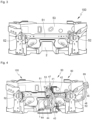
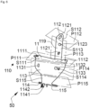
- the vehicle comprises an arrangement 50 comprising a fixing part 1, the fixing part 1 making it possible to fix the cables and pipes of a set of equipment 60 of the motor vehicle 100.
- the arrangement 50 further comprises a pipe or a second wiring, the given pipe or second wiring 41, 42, 43, 44 being distinct from the at least one first wiring 45, 46, and the fixing part 1 comprises at least one second fixing zone for the pipe or second wiring 41, 42, 43, 44.
- fixing area is used to designate a surface portion of the fixing part 1 which comprises an arrangement contributing to fixing a pipe or wiring.
- the arrangement may simply be a surface portion serving as a support, and/or at least one hole made in the surface portion, and/or a threaded axis and/or a centering pin fixed to the surface portion.
- Other embodiments of the fixing part, in particular of the arrangement, are also possible.
- the fixing part 1 comprises fixing means 1111, 1112, 1121, 1122, 1123, 1131, 1132, 1133, 1141, 1142, 1151, 1211, 1212, 1221, 1222 for each pipe taken from among the first, second, third and fourth pipes and for each wiring taken from among the first, second and third wirings.
- the third wiring 47 allows the battery management computer 63 to retrieve information relating to the battery, for example the charge level of the battery 61.
- fastening part designates a part intended to arrange at least one pipe or wiring in a given fastening area of a motor vehicle.
- a fastening part simplifies the mounting of the at least one pipe or wiring in the given area.
- the fixing part 1 is made of stamped sheet metal. In one embodiment, at least one surface S115 of the fixing part The fastener includes a stamping, i.e. a groove, to increase its rigidity.
- the attachment of the surface S111 thus determines the position of the other surfaces S112 to S116 of the main part 11 of the attachment part 1 in the vehicle 100. Furthermore, as will be described later in the document, the surface S121 of the additional part 12 is attached to the surface S114 of the main part 11. The attachment of the surface S111 thus determines the position of the surfaces S121 and S122 of the additional part 12 of the attachment part 1.
- the surface S122 comprises a seventh fixing zone 122 comprising a round hole 1221 and a substantially oblong hole 1222 intended to collaborate with a male fixing means for fixing water pipes 43, 44 respectively connecting the water heater 64 and the cooling circuit of the battery 62 to the radiator 65 of the passenger compartment.
- a step E1 of fixing the first part 11 of the fixing piece 1 on the reinforcing crosspiece 51 the surface S111 of the main part 11 of the fixing piece 1 is placed in contact with the upper face 511 of the crosspiece 51, the upper face 511 of the crosspiece 51 itself being substantially parallel to a plane (X, Y).
- the surface S111 is placed on the upper face 511 of the crosspiece 51.
- the step of fixing the second part 12 of the fixing part 1 on the first part 11 of the fixing part 1 can be carried out directly after the step E2 of installing the brake assist system, as shown in particular in the figure 10 . Alternatively, it may be preceded by a step E3 of fixing the first, second and third wirings 45, 46, 47 on the first part 11 of the fixing part 1.
- step E3 illustrated by the figure 12 , the first and second wirings 45, 46, which correspond to the wirings of the charging socket, are fixed to the fixing zones 114 and 115 of the first part.
- the third wiring 47 corresponding to the wiring connecting the battery to the battery management computer 63, is fixed to the first zone 111 of the main part 11.
- the fixing points of the wiring 45, 46, 47 on the fixing part 1 are the only fixing points of these wirings during several stages of assembly of the vehicle.
Landscapes
- Engineering & Computer Science (AREA)
- Mechanical Engineering (AREA)
- Battery Mounting, Suspending (AREA)
- Arrangement Or Mounting Of Propulsion Units For Vehicles (AREA)
- Electric Propulsion And Braking For Vehicles (AREA)
Applications Claiming Priority (1)
| Application Number | Priority Date | Filing Date | Title |
|---|---|---|---|
| FR2308000A FR3151553B1 (fr) | 2023-07-25 | 2023-07-25 | Arrangement pour véhicule automobile. |
Publications (1)
| Publication Number | Publication Date |
|---|---|
| EP4497637A1 true EP4497637A1 (de) | 2025-01-29 |
Family
ID=89661339
Family Applications (1)
| Application Number | Title | Priority Date | Filing Date |
|---|---|---|---|
| EP24187610.1A Pending EP4497637A1 (de) | 2023-07-25 | 2024-07-10 | Anordnung für ein kraftfahrzeug |
Country Status (2)
| Country | Link |
|---|---|
| EP (1) | EP4497637A1 (de) |
| FR (1) | FR3151553B1 (de) |
Citations (5)
| Publication number | Priority date | Publication date | Assignee | Title |
|---|---|---|---|---|
| FR2997917A1 (fr) * | 2012-11-13 | 2014-05-16 | Renault Sa | "vehicule automobile a moteur arriere comportant un compartiment avant optimise" |
| US20200079305A1 (en) * | 2018-09-12 | 2020-03-12 | Honda Motor Co., Ltd. | Vehicle |
| US20200101813A1 (en) * | 2018-10-02 | 2020-04-02 | Honda Motor Co., Ltd. | Electrical apparatus |
| EP4049899A1 (de) * | 2021-02-26 | 2022-08-31 | Suzuki Motor Corporation | Elektrische ausrüstung |
| US20220371420A1 (en) * | 2020-02-19 | 2022-11-24 | Mitsubishi Jidosha Kogyo Kabushiki Kaisha | Power line routing structure in hybrid vehicle |
-
2023
- 2023-07-25 FR FR2308000A patent/FR3151553B1/fr active Active
-
2024
- 2024-07-10 EP EP24187610.1A patent/EP4497637A1/de active Pending
Patent Citations (5)
| Publication number | Priority date | Publication date | Assignee | Title |
|---|---|---|---|---|
| FR2997917A1 (fr) * | 2012-11-13 | 2014-05-16 | Renault Sa | "vehicule automobile a moteur arriere comportant un compartiment avant optimise" |
| US20200079305A1 (en) * | 2018-09-12 | 2020-03-12 | Honda Motor Co., Ltd. | Vehicle |
| US20200101813A1 (en) * | 2018-10-02 | 2020-04-02 | Honda Motor Co., Ltd. | Electrical apparatus |
| US20220371420A1 (en) * | 2020-02-19 | 2022-11-24 | Mitsubishi Jidosha Kogyo Kabushiki Kaisha | Power line routing structure in hybrid vehicle |
| EP4049899A1 (de) * | 2021-02-26 | 2022-08-31 | Suzuki Motor Corporation | Elektrische ausrüstung |
Also Published As
| Publication number | Publication date |
|---|---|
| FR3151553B1 (fr) | 2025-07-18 |
| FR3151553A1 (fr) | 2025-01-31 |
Similar Documents
| Publication | Publication Date | Title |
|---|---|---|
| EP3310604B1 (de) | Batterieträgeranordnung für ein hybridfahrzeug | |
| EP3765337B1 (de) | Vorrichtung zur befestigung eines sensors an einem fahrzeug sowie montageverfahren | |
| EP4605272A1 (de) | Anordnung für ein fahrzeug mit einer vorrichtung zur abstützung mindestens einer in der frontstruktur des fahrzeugs vorgesehenen komponente | |
| EP4497637A1 (de) | Anordnung für ein kraftfahrzeug | |
| US11192437B1 (en) | Vehicle load management system and method | |
| EP3380366B1 (de) | Vorrichtung zur montage eines radars für ein kraftfahrzeug | |
| FR2965226A1 (fr) | Dispositif pour le guidage d'un flux d'air pour vehicule automobile et face avant comportant un tel dispositif | |
| EP4561869B1 (de) | Kabelkanal zur vorfixierung einer fahrzeugbatterie | |
| EP3829963B1 (de) | Fahrzeug mit hinterer unterbodenverkleidung mit einer abfasung | |
| EP3775650B1 (de) | Vorrichtung zum halten und thermischen schützen von elementen | |
| EP3887180B1 (de) | Kraftfahrzeug mit einer im motorraum montierten heizungs-, lüftungs- und klimaanlage | |
| FR3063533A1 (fr) | Support de moteur thermique en deux parties | |
| FR3137650A1 (fr) | Collecteur d’auvent pour véhicule automobile doté d’un conduit d’air intégré | |
| WO2025219288A1 (fr) | Arrangement pour véhicule automobile | |
| EP4025477B1 (de) | Kotflügeldeflektoranordnung mit einem element zum blockieren einer öffnung für ein fahrzeug | |
| FR3166112A1 (fr) | Arrangement pour véhicule automobile. | |
| EP3551504B1 (de) | Motorenraumvorrichtung für ein kraftfahrzeug mit einem elektronischen steuergerät | |
| FR3167357A1 (fr) | Ensemble pour véhicule automobile et véhicule automobile équipé d’un tel ensemble | |
| FR3153028A1 (fr) | Véhicule automobile comprenant une machine électrique, un compresseur de climatisation formant support de ladite machine électrique | |
| EP4538151A1 (de) | Anordnung für ein kraftfahrzeug mit einer verriegelungsanordnung einer haube und einem tragrahmenelement | |
| FR3130206A1 (fr) | Dispositif de raccordement pour tubulure de remplissage, vehicule et procede de raccordement sur la base d’un tel dispositif | |
| WO2025073674A1 (fr) | Dispositif de protection pour au moins un connecteur électrique | |
| FR3161188A1 (fr) | Structure arrière de soubassement de véhicule automobile et déflecteur pour une telle structure | |
| FR3154675A1 (fr) | Élément de carrosserie de véhicule automobile et véhicule automobile comprenant un tel élément | |
| FR3073269A1 (fr) | Systeme de protection thermique d’un conduit |
Legal Events
| Date | Code | Title | Description |
|---|---|---|---|
| PUAI | Public reference made under article 153(3) epc to a published international application that has entered the european phase |
Free format text: ORIGINAL CODE: 0009012 |
|
| STAA | Information on the status of an ep patent application or granted ep patent |
Free format text: STATUS: THE APPLICATION HAS BEEN PUBLISHED |
|
| AK | Designated contracting states |
Kind code of ref document: A1 Designated state(s): AL AT BE BG CH CY CZ DE DK EE ES FI FR GB GR HR HU IE IS IT LI LT LU LV MC ME MK MT NL NO PL PT RO RS SE SI SK SM TR |
|
| STAA | Information on the status of an ep patent application or granted ep patent |
Free format text: STATUS: REQUEST FOR EXAMINATION WAS MADE |
|
| 17P | Request for examination filed |
Effective date: 20250710 |