EP4497891A1 - Dachziegel und schneeschutz - Google Patents
Dachziegel und schneeschutz Download PDFInfo
- Publication number
- EP4497891A1 EP4497891A1 EP24189449.2A EP24189449A EP4497891A1 EP 4497891 A1 EP4497891 A1 EP 4497891A1 EP 24189449 A EP24189449 A EP 24189449A EP 4497891 A1 EP4497891 A1 EP 4497891A1
- Authority
- EP
- European Patent Office
- Prior art keywords
- roof
- roofing tile
- snow guard
- roofing
- plate element
- Prior art date
- Legal status (The legal status is an assumption and is not a legal conclusion. Google has not performed a legal analysis and makes no representation as to the accuracy of the status listed.)
- Pending
Links
Images




Classifications
-
- E—FIXED CONSTRUCTIONS
- E04—BUILDING
- E04D—ROOF COVERINGS; SKY-LIGHTS; GUTTERS; ROOF-WORKING TOOLS
- E04D13/00—Special arrangements or devices in connection with roof coverings; Protection against birds; Roof drainage ; Sky-lights
- E04D13/10—Snow traps ; Removing snow from roofs; Snow melters
-
- E—FIXED CONSTRUCTIONS
- E04—BUILDING
- E04D—ROOF COVERINGS; SKY-LIGHTS; GUTTERS; ROOF-WORKING TOOLS
- E04D1/00—Roof covering by making use of tiles, slates, shingles, or other small roofing elements
- E04D1/34—Fastenings for attaching roof-covering elements to the supporting elements
- E04D1/3405—Fastenings for attaching roof-covering elements to the supporting elements for eaves, valley, or verge tiles
-
- E—FIXED CONSTRUCTIONS
- E04—BUILDING
- E04D—ROOF COVERINGS; SKY-LIGHTS; GUTTERS; ROOF-WORKING TOOLS
- E04D13/00—Special arrangements or devices in connection with roof coverings; Protection against birds; Roof drainage ; Sky-lights
- E04D13/04—Roof drainage; Drainage fittings in flat roofs, balconies or the like
- E04D13/0404—Drainage on the roof surface
- E04D13/0459—Drainage borders, e.g. dripping edges, gravel stops or dispersers
-
- E—FIXED CONSTRUCTIONS
- E04—BUILDING
- E04D—ROOF COVERINGS; SKY-LIGHTS; GUTTERS; ROOF-WORKING TOOLS
- E04D13/00—Special arrangements or devices in connection with roof coverings; Protection against birds; Roof drainage ; Sky-lights
- E04D13/15—Trimming strips; Edge strips; Fascias; Expansion joints for roofs
- E04D13/158—Trimming strips; Edge strips; Fascias; Expansion joints for roofs covering the overhang at the eave side, e.g. soffits, or the verge of saddle roofs
-
- E—FIXED CONSTRUCTIONS
- E04—BUILDING
- E04D—ROOF COVERINGS; SKY-LIGHTS; GUTTERS; ROOF-WORKING TOOLS
- E04D1/00—Roof covering by making use of tiles, slates, shingles, or other small roofing elements
- E04D1/34—Fastenings for attaching roof-covering elements to the supporting elements
- E04D2001/3408—Fastenings for attaching roof-covering elements to the supporting elements characterised by the fastener type or material
- E04D2001/3414—Metal strips or sheet metal
Definitions
- the present invention relates to a roofing tile guard to catch roofing tiles loosening from a roof before the roofing tile falls from the roof and potentially injures anyone under the roof.
- the invention can also function as a snow guard in the winter to prevent snow and ice sliding down from the roof and injuring anyone under the roof.
- roofing tiles are often arranged on buildings with a certain height, and many times on buildings with roofs having a relatively high degree of inclination. Overall, this poses a great potential danger over time as the nails holding the roofing tiles in place corrode, which can cause the roofing tiles to fall.
- a roofing tile of 1kg or more falling from a roof several meters high will have a great potential of damage and in the worst case can have a fatal outcome if a person is hit in the head by a falling roofing tile.
- roofing tile guards where you use upward projecting brackets that are attached to the wall or a truss under the roof, and an elongated grid unit that is attached to the brackets.
- the problem is that the brackets are often installed so that an opening or gap is formed between the grid unit and the roofing tile that is large enough for a roofing tile to slip through the gap, for example a slate tile that is flat and not very high.
- Another problem with these known solutions is that the grid unit has a lower longitudinal element that collects leaves and other trash that will be able to build up on the upper side of the grid unit.
- snow guards are installed one way up on the roof as they are exclusively intended for snow and thus tiles/snow that are located below the snow guard will not be caught.
- brackets must be installed on the wall or trusses and then the grid units must be attached to the brackets. This also means that several different elements must be kept in order before and during installation.
- roofing tile- and snow guard as defined in claim 1 and uses of the roofing tile- and snow guard as specified in claims 19-21. Further features of the present roofing tile- and snow guard are defined in the dependent patent claims 2-18.
- the present roofing tile- and snow guard can be retrofitted to most roofs and will catch loose tiles so that they do not fall to the ground with the risk of hitting a person or causing injury. We are not aware of anything similar that catches falling tiles on the market today.
- the roofing tile- and snow guard can be produced in a stainless material, for example stainless steel, but other stainless metals and other suitable materials can also be used, for example a plastic material, such as PVC.
- the roofing tile- and snow guard has a plate element that can be installed between battens on the roof and the roofing tiles of the roof. This plate element can, for example, be 2mm thick so that it can easily be pushed under the roofing tiles when the roofing tile- and snow guard is installed on an existing roof.
- the roofing tile- and snow guard has a plurality of catch elements which are preferably cut out of said plate element or optionally installed on the plate element. These catch elements are bent to form an angle with the plate element, preferably around 90 degrees.
- the plate element is preferably placed so that the catch elements stand next to, or so to speak, next to the roofing tile in front of the front row of tiles on the roof, and so that the catch elements protrude at least 5-10 cm beyond the roofing tile. In this way, the catch elements will catch and stop tiles sliding down. If the roofing tile- and snow guard is also to stop snow and ice falling from the roof, the catch elements can be longer than if the roofing tile- and snow guard is only to prevent roofing tiles from falling from the roof.
- roofing tile- and snow guard can also be arranged with a pre-cut hole at the top so that a longitudinal angle or an attachment for a pipe can be screwed in so that we form an upper edge as well, to better stop snow. This will also reinforce the catch elements at the same time.
- the roofing tile- and snow guard can also comprise one of more support elements arranged forming an angle with respect to the plate element.
- the angle that the support element forms with the plate element will preferably be adapted to the angle between the roof and the leading-edge board of the roof located behind fittings guiding water down into the rain gutter such that the support element bears against, or at least in largest possible degree bears against, the leading-edge board or possibly the fitting located outside the leading-edge board.
- These support elements can be arranged with holes to be used to attach the roofing tile- and snow guard to the leading-edge board of the roof.
- roofing tile- and snow guard to prevent fall of roofing tiles and/or snow slide from a roof
- roofing tile- and snow guard comprises a plate element being elongated and having a first side edge and a second side edge, both extending in the longitudinal direction of the plate element, which plate element having an upper surface facing outwards when the roofing tile- and snow guard is installed on the roof and a lower surface facing inwards when the roofing tile- and snow guard is installed on the roof, which roofing tile- and snow guard further comprises a plurality of catch element fixedly arranged along the first side edge, which catch elements extends outwards from the plate element's upper surface.
- outwards it should here be understood as facing outwards, that is towards the surroundings and away from the interior of the building with the roof.
- inwards here is to be understood as facing inwards, that is towards the interior of the building with the roof.
- the catch elements are basically designed as finger like elements. Further are the catch elements separate elements not connected to the other catch elements except from via the plate element which all catch elements are protruding outwards from. The catch elements are neither connected to other elements than the plate element. The catch elements are therefore separate elements. That means that leaves and other trash can pass the roofing tile- and snow guard, while falling roofing tiles are being stopped by the catch elements.
- the catch elements normally extend a distance out from the plate element's upper surface which is at least two times larger than the thickness of one roofing tile on a roof where the roofing tile- and snow guard is being installed.
- the length of the catch elements are three times the thickness/height of one roofing tile or more.
- the thickness of one roofing tile should be understood as an average thickness of the roofing tile on the roof.
- the catch elements can further, if wanted, have different lengths.
- At least one of the catch elements comprises an outer section and an inner section, where the outer section forms an angle with the inner section, preferably an obtuse angle.
- catch elements are to be arranged with such an angle an outer section and an inner section, preferably all catch elements are arranged with an angle between respective inner sections and outer sections.
- the angle can, for example, be around 135 degrees, but can also lie between 100 degrees and 170 degrees.
- the catch elements are preferably an integrated part of the plate element. That means that a catch element gap is cut out of the plate element and the elements left, i.e., the catch elements, are bent outwards from the plate element.
- the catch elements can be separate elements that are installed on the plate element, for example with screws, bolts, adhesion, welding, or other suitable fastening elements.
- a catch element gap between two adjacent catch elements has preferably a catch element distance that is less than the smallest width of a roofing tile of the roofing tiles on a roof on where the roofing tile- and snow guard is being installed.
- Minimum roofing tile width is the smallest distance across a roofing tile, i.e., the diameter of the smallest hole that the tile will be able to pass through. If the roofing tile has a circular form, minimum roofing tile width will be the diameter of the roofing tile.
- the catch element distance will preferably be a good deal smaller than the roofing tile width to avoid that roofing tiles that come loos and slide down the roof are able to get past the catch elements in the catch element gaps. Typically, the catch element distance can lie in the range 50-90 % of the smallest roofing tile width.
- the catch element distance can vary along the plate element, for example if different types of roofing tiles are used on a roof where the different types of roofing tiles have different smallest roofing tile width.
- the plate element is preferably adapted to be arranged below a lower row of roofing tiles on the roof. This means that the plate element has a thickness allowing it to fit under the roofing tile.
- the thickness of the plate element lies preferably in the range 1 mm - 5 mm, and can typically be 2 mm.
- the plate element can extend up under two or possibly more, of the lower rows if the plate element's width, i.e. the distance between first side edge and second side edge, is large enough.
- the plate element is preferably arranged with at least one fastening means such that the plate element can be attached to the roof.
- the fastening means can be a through opening in the plate element such that the plate element can be attached to the roof with a screw or a bolt or an other suitable fastening means.
- the plate element is preferably arranged with a plurality of fastening means, for example a plurality of through openings such that the plate element can be attached to the roof with two or more screws or other suitable fastening means.
- the roofing tile- and snow guard can further comprise at least one support element projecting out from the plate element and adapted to be attached to the roof construction of the roof.
- the at least one support element is preferably adapted to bears against the leading-edge board of the roof when the roofing tile- and snow guard is arranged on the roof, or against a fitting located outside the leading-edge board when the roofing tile- and snow guard is arranged on the roof.
- the at least one support element is preferably projecting out from the lower surface of the plate element, i.e., on the opposite side of the plate element compared to the catch elements.
- the at least one support element is an integrated part of the plate element.
- the plate element can, for example, be made by cutting out two sections in the plate element such that a tongue is formed and that the tongue is bent outwards from the plate element and thereby forms the at least one support element.
- the at least one support element is preferably forming an angle with the plate element being adapted to the angle of inclination of the roof and the angle of inclination of the lower, transverse leading-edge board of the roof, which normally is arranged vertical or perpendicular to the roof.
- the at least one support element can be a separate part being installed on the plate element, for example with screws, bolts, adhesive, welding, or other suitable fastening means.
- the at least one support element can further be adjustable attached to the plate element so that each support element can be adjusted to the distance to the leading-edge board of the roof or fitting located outside the leading-edge board as this distance can vary in the longitudinal direction of the roof.
- the at least one support element can further be arranged with at least one fastening means, so that the at least one support element can be attached to the roof.
- the fastening means can be a through opening in the at least one support element, so that the at least one support element can be attached to the roof with a screw or a bolt or a similar suitable fastening means.
- the roofing tile- and snow guard is preferably made of a metal or a plastic material or a combination of metal and a plastic material.
- the metal can for example be stainless steel or another stainless metal.
- the plastic material can for example be PVC but can also be another plastic material with the required strength and durability.
- roofing tile- and snow guard as defined above for installation on a roof of a building to prevent snow and/or ice from falling from the roof, where the roofing tile- and snow guard comprises one, some or all the alternative features as described above, possibly without any of the alternative features.
- roofing tile- and snow guard as defined above for installation on a roof of a building where the roof is arranged with roofing tiles to prevent roofing tiles from falling from the roof, where the roofing tile- and snow guard comprises one, some or all the alternative features as described above, possibly without any of the alternative features.
- roofing tile- and snow guard as defined above for installation on a roof of a building where the roof is arranged with roofing tiles to prevent roofing tiles from falling from the roof and to prevent snow and/or ice from falling from the roof, where the roofing tile- and snow guard comprises one, some or all of the alternative features as described above, possibly without any of the alternative features.
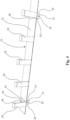
- the roofing tile- and snow guard comprises a plate element 12 with a first side edge 13 and a second side edge 14 extending in a longitudinal direction of the plate element 12 and thereby also in a longitudinal direction of the roofing tile- and snow guard 10.
- the plate element 12 has further a first transverse side edge 15 and a second transverse side edge 16 extending between the first side edge 13 and the second side edge 14.
- the plate element 12 is therefore mainly rectangular in shape.
- the thickness of the plate element 12 is, for example, in the range 1-5 mm, and typically 2 mm.
- the plate element is preferably made of a stainless metal, such as stainless steel, but other stainless material can also be used as long as they are strong enough.
- the plate element 12 can be formed with at least one fastening means 19 as indicated on figure 1 .
- the at least one fastening means 19 can be at least one, but preferably to or more through openings such that the plate element 12 can be attached to a roof 40 with screws, bolts, or similar fastening means.
- the roofing tile- and snow guard 10 further comprises a plurality of catch elements 24 projecting up from the plate element 12 along the first side edge 13 of the plate element.
- the catch elements 24 is preferably integrated with the plate element 12. I.e. that the catch elements 24 and the plate element are made with starting point in a single plate element where, during the manufacturing of the roofing tile- and snow guard 10, the catch element gaps 20 are cut out between what will become two adjacent catch elements 24 and down to what will become a part of the first side edge 13 when the roofing tile- and snow guard 10 is completed.
- a catch element gap 20 is indicated on figure 2 with dotted lines between two catch elements 24.
- the catch elements 24 can be bent up along the first side edge 13 so that the catch elements form a required angle with the plate element 12, preferably about 90 degrees.
- the catch elements 24 is formed with a catch element width 28 as indicated on figure 2 which must be so wide that the catch elements are stiff and strong enough to catch roofing tiles 43 that come sliding from the top of the roof 40 (see figure 5-7 ).
- the catch elements can have a catch element width 28 of about 3-5 cm, but it can be both larger and smaller than this.
- a row of catch elements 24 having a catch element distance 21 are formed between them, i.e., the distance between two adjacent catch elements 24 as shown on figure 2 .
- the catch element distance 21 must be adapted to the size of the roofing tile 43 on the roof 40 where the roofing tile- and snow guard 10 shall be installed to avoid that roofing tiles 43 loosening and sliding down the roof 40 manage to get through the roofing tile- and snow guard 10 in one of the catch element gaps 20 and falls from the roof with a potential danger of injuring persons and equipment/devices located under the roof.
- the catch element distance 21 must therefore be less than the smallest roofing tile width 44, i.e., the smallest distance across the roofing tiles 43 as indicated on figure 5 .
- the catch element distance 21 can be in the range 50-90 % of the smallest roofing tile width 44 of the roofing tile 43.
- the catch elements 24 can be formed with an inner section 26 and an outer section 25.
- the inner section 26 and the outer section 25 are preferably separated of a breaking edge 27, where the outer section of the catch elements 24 are broken so that they form an angle with the inner section 26 of the catch elements 24.
- the angle is preferably obtuse, and can, for example be about 135 degrees, but can lie in the range between 100 degrees and 170 degrees. If the catch elements 24 shall be formed with such outer sections 25, the catch elements 24 are preferably broken along the breaking edge 27 so that the outer section 25 forms a required angle with the inner section 26 before the catch arms 24 are bent up to form a required angle with the plate element 12 as explained above.
- the roofing tile- and snow guard 10 can also be formed with at least one, but preferably two or more support elements 31, as indicated on the figures 3 and 4 .
- the support elements 31 can be formed by cutting out two slots in the plate element 12 in from the other side edge 14 to a required depth giving a required length of the support elements 31. After the slots are being cut out, lips formed can, with a first side edge 32 and a second side edge 33, be bent out from the plate element 12 at the end of the slots along a breaking edge 34, preferably in opposite direction of the catch elements 24 as indicated on the figures, so that the support elements 31 are formed.
- the support elements 31 is bent so that they form a required angle with the plate element 12, and preferably so that they will bear against the leading-edge board of the roof 40 when the roofing tile- and snow guard 10 is arranged on the roof 40, or against a fitting 45 laying outside the leading-edge board when the roofing tile- and snow guard 10 is arranged on the roof 40 as indicated on the figures 6 and 7 .
- Each support element can be arranged with at least one fastening means 35 so that they can be attached to the leading-edge board of the roof 40 and/or a fitting 45 laying outside the leading-edge board when the roofing tile- and snow guard 10 is arranged on the roof 40.
- the fastening means 35 can, for example, be a through hole so that the support elements 31 can be attached with a screw, a bolt, or another suitable fastening means.
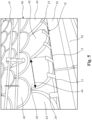
- the roofing tile- and snow guard 10 is shown installed on a roof 40.
- the roof 40 will normally have a fitting 45 installed on the outside of the leading-edge board of the roof 40 and guides water down into the rain gutter 42.
- the roof 40 as shown on the figures is arranged with roofing tiles 43 having an oblong form and a minimum roofing tile width 44 across the roofing tile 43 as indicated on figure 5 .
- the minimum roofing tile width 44 is larger than the catch element distance 21 as shown on the figures, so that roofing tiles 43 that loosen and slide down the roof 40 cannot pass in the catch element gap 20 between two adjacent catch elements 24 and fall from the roof but are being caught by one of the catch elements 24.
- the roofing tile- and snow guard 10 can be installed both on the roof of a building under construction and retrofitted on the roof 40 of an existing building. If the roofing tile- and snow guard 10 is to be retrofitted on a roof 40, the plate element 12 is brought up under the roofing tile 43 so that any support elements 31 as the roofing tile- and snow guard 10 are designed with, bear against the leading-edge board of the roof 40 or a fitting 45 laying outside the leading-edge board.
- the plate element 12 can be attached to the roof 40 with screws or similar by removing the whole or part of the lower row of roofing tiles 43 to get to the fastening means 19 and have the plate element attached to the roof 40. After the plate element 12 is attached to the roof 40, the roofing tile 43 can be laid back in their respective places.
- roofing tile- and snow guard 10 is formed with support elements 31, the roofing tile- and snow guard 10 is attached by attaching the support elements 31 to the leading-edge board of the roof 40 and possibly the fitting 45, which can be laid on the outside of the leading-edge board.
- roofing tile- and snow guard 10 by attaching the plate element 12 to the roof 40 and let possible support elements 31 function only as support elements, i.e., that they cannot be attached to any part of the roofing structure.
- the roofing tile- and snow guard 10 can alternatively only be attached by attaching the support elements 31 to the roofing structure, preferably the leading-edge board as also possibly the fitting 45 laying on the outside of the leading-edge board.
- the roofing tile- and snow guard 10 can alternatively be attached by both attaching the plate element 12 to the roof 40 and the support elements 31 to the roofing structure, preferably the leading-edge board which and possibly the fitting 45 which is located outside the leading-edge board.
- the traditional snow guards 41 arranged further up on the roof 40 than the present roofing tile- and snow guard 10 which is arranged at the lower edge of the roof 40 so that the catch elements 24 projects up below the lowest row of roofing tiles 43 on the roof 40.
- the traditional snow guards 40 is not capable to catch neither snow or ice or roofing tiles that loosens and fall from the roof 40 from a place below the snow guard 41.
- the present roofing tile- and snow guard 10 on the other hand, will be capable to catch all roofing tiles 43 on the roof 40 and all snow and ice that had to fall from the roof 40.
- roofing tile- and snow guard 12 Plate element 13 First side edge 14 Second side edge 15 First transverse side edge 16 Second transverse side edge 17 Upper surface 18 Lower surface 19 Fastening means (e.g. a hole for a fastening element, such as a screw) 20 Catch element gap 21 Catch element distance 24 Catch element 25 Outer section 26 Inner section 27 Breaking edge 28 Catch element width 31 Support element 32 First side edge 33 Second side edge 34 Breaking edge 35 Fastening means (e.g., a hole for a fastening element, such as a screw) 36 First slot edge 37 Second slot edge 40 Roof 41 Traditional snow guard 42 Rain gutter 43 roofing tile 44 roofing tile width (smallest distance across a roofing tile - smallest hole a roofing tile can pass through) 45 Fitting (that bears against the leading-edge board)
Landscapes
- Engineering & Computer Science (AREA)
- Architecture (AREA)
- Civil Engineering (AREA)
- Structural Engineering (AREA)
- Mechanical Engineering (AREA)
- Buildings Adapted To Withstand Abnormal External Influences (AREA)
Applications Claiming Priority (1)
| Application Number | Priority Date | Filing Date | Title |
|---|---|---|---|
| NO20230824A NO349503B1 (no) | 2023-07-28 | 2023-07-28 | Taksteinsfanger og snøfanger |
Publications (1)
| Publication Number | Publication Date |
|---|---|
| EP4497891A1 true EP4497891A1 (de) | 2025-01-29 |
Family
ID=87888079
Family Applications (1)
| Application Number | Title | Priority Date | Filing Date |
|---|---|---|---|
| EP24189449.2A Pending EP4497891A1 (de) | 2023-07-28 | 2024-07-18 | Dachziegel und schneeschutz |
Country Status (2)
| Country | Link |
|---|---|
| EP (1) | EP4497891A1 (de) |
| NO (1) | NO349503B1 (de) |
Citations (6)
| Publication number | Priority date | Publication date | Assignee | Title |
|---|---|---|---|---|
| US4096671A (en) * | 1977-06-09 | 1978-06-27 | Monier Colourtile Pty. Ltd. | Roof eave assembly |
| JPH10273953A (ja) * | 1997-03-31 | 1998-10-13 | Natl House Ind Co Ltd | 雪止め金具の設置構造 |
| DE202009005836U1 (de) * | 2009-04-18 | 2009-08-13 | Krautscheid, Kurt | Grundelement für die Verbindung mit einer Rückhalteleiste |
| DE102008059134A1 (de) * | 2008-11-26 | 2010-05-27 | Georg Meyer | Schutzvorrichtung |
| NO333095B1 (no) * | 2011-10-28 | 2013-03-04 | Lonevag Beslagfabrikk As | Gradrennelist |
| AT514620B1 (de) * | 2013-07-23 | 2015-05-15 | Gerhard Grollegg | Schneehaltevorrichtung |
-
2023
- 2023-07-28 NO NO20230824A patent/NO349503B1/no unknown
-
2024
- 2024-07-18 EP EP24189449.2A patent/EP4497891A1/de active Pending
Patent Citations (6)
| Publication number | Priority date | Publication date | Assignee | Title |
|---|---|---|---|---|
| US4096671A (en) * | 1977-06-09 | 1978-06-27 | Monier Colourtile Pty. Ltd. | Roof eave assembly |
| JPH10273953A (ja) * | 1997-03-31 | 1998-10-13 | Natl House Ind Co Ltd | 雪止め金具の設置構造 |
| DE102008059134A1 (de) * | 2008-11-26 | 2010-05-27 | Georg Meyer | Schutzvorrichtung |
| DE202009005836U1 (de) * | 2009-04-18 | 2009-08-13 | Krautscheid, Kurt | Grundelement für die Verbindung mit einer Rückhalteleiste |
| NO333095B1 (no) * | 2011-10-28 | 2013-03-04 | Lonevag Beslagfabrikk As | Gradrennelist |
| AT514620B1 (de) * | 2013-07-23 | 2015-05-15 | Gerhard Grollegg | Schneehaltevorrichtung |
Also Published As
| Publication number | Publication date |
|---|---|
| NO349503B1 (no) | 2026-02-02 |
| NO20230824A1 (no) | 2023-08-15 |
Similar Documents
| Publication | Publication Date | Title |
|---|---|---|
| US9284735B2 (en) | Debris repelling filtering device for roof gutters | |
| US8276321B2 (en) | Expanded metal gutter cover and method of installation | |
| US5457916A (en) | Rain gutter protection device | |
| US7793465B2 (en) | Gutter guard | |
| US8474192B2 (en) | Screened gutter protection | |
| US8528262B2 (en) | Gutter-locking gutter protection | |
| US8776444B2 (en) | Low-profile rain gutter screen | |
| US20090300995A1 (en) | Corrugated shield | |
| US12129654B2 (en) | Eavestrough debris guard | |
| US10053867B2 (en) | Apparatus for diverting water | |
| US8978312B2 (en) | Rainwater runoff diverting attachment for building roofs | |
| US7278239B1 (en) | Gutter protector and guttering incorporating same | |
| US20060283096A1 (en) | Gutter and roof protection system | |
| US7665247B1 (en) | Gutter debris deflector having multiple slots | |
| US9915071B2 (en) | Roof ice diverter | |
| US20040206010A1 (en) | Eaves trough assembly with stepped down shield | |
| US20250297480A1 (en) | Gutter installation and gutter mesh fastener | |
| US20200095771A1 (en) | Gutter cover system | |
| GB2488434A (en) | Gutter debris guard to protect from accumulation of debris in a gutter | |
| US20040083657A1 (en) | Gutter and cover system | |
| NO349503B1 (no) | Taksteinsfanger og snøfanger | |
| US20250163702A1 (en) | Patio awning rain gutter device and related methods | |
| US10619352B1 (en) | Rain gutter for tin roof or the like | |
| AU748649B2 (en) | Gutter protector and guttering incorporating same | |
| AU733074B3 (en) | Gutter protector and guttering incorporating same |
Legal Events
| Date | Code | Title | Description |
|---|---|---|---|
| PUAI | Public reference made under article 153(3) epc to a published international application that has entered the european phase |
Free format text: ORIGINAL CODE: 0009012 |
|
| STAA | Information on the status of an ep patent application or granted ep patent |
Free format text: STATUS: THE APPLICATION HAS BEEN PUBLISHED |
|
| AK | Designated contracting states |
Kind code of ref document: A1 Designated state(s): AL AT BE BG CH CY CZ DE DK EE ES FI FR GB GR HR HU IE IS IT LI LT LU LV MC ME MK MT NL NO PL PT RO RS SE SI SK SM TR |
|
| STAA | Information on the status of an ep patent application or granted ep patent |
Free format text: STATUS: REQUEST FOR EXAMINATION WAS MADE |
|
| 17P | Request for examination filed |
Effective date: 20250729 |