EP4497913A1 - In-situ-motorschaufelprozesskompensierte resonanzprüfung - Google Patents
In-situ-motorschaufelprozesskompensierte resonanzprüfung Download PDFInfo
- Publication number
- EP4497913A1 EP4497913A1 EP24188087.1A EP24188087A EP4497913A1 EP 4497913 A1 EP4497913 A1 EP 4497913A1 EP 24188087 A EP24188087 A EP 24188087A EP 4497913 A1 EP4497913 A1 EP 4497913A1
- Authority
- EP
- European Patent Office
- Prior art keywords
- inspection device
- inspection
- component
- signals
- various embodiments
- Prior art date
- Legal status (The legal status is an assumption and is not a legal conclusion. Google has not performed a legal analysis and makes no representation as to the accuracy of the status listed.)
- Pending
Links
Images


Classifications
-
- F—MECHANICAL ENGINEERING; LIGHTING; HEATING; WEAPONS; BLASTING
- F01—MACHINES OR ENGINES IN GENERAL; ENGINE PLANTS IN GENERAL; STEAM ENGINES
- F01D—NON-POSITIVE DISPLACEMENT MACHINES OR ENGINES, e.g. STEAM TURBINES
- F01D21/00—Shutting-down of machines or engines, e.g. in emergency; Regulating, controlling, or safety means not otherwise provided for
- F01D21/003—Arrangements for testing or measuring
-
- G—PHYSICS
- G01—MEASURING; TESTING
- G01N—INVESTIGATING OR ANALYSING MATERIALS BY DETERMINING THEIR CHEMICAL OR PHYSICAL PROPERTIES
- G01N3/00—Investigating strength properties of solid materials by application of mechanical stress
- G01N3/02—Details
-
- G—PHYSICS
- G01—MEASURING; TESTING
- G01N—INVESTIGATING OR ANALYSING MATERIALS BY DETERMINING THEIR CHEMICAL OR PHYSICAL PROPERTIES
- G01N29/00—Investigating or analysing materials by the use of ultrasonic, sonic or infrasonic waves; Visualisation of the interior of objects by transmitting ultrasonic or sonic waves through the object
- G01N29/04—Analysing solids
- G01N29/043—Analysing solids in the interior, e.g. by shear waves
-
- F—MECHANICAL ENGINEERING; LIGHTING; HEATING; WEAPONS; BLASTING
- F05—INDEXING SCHEMES RELATING TO ENGINES OR PUMPS IN VARIOUS SUBCLASSES OF CLASSES F01-F04
- F05D—INDEXING SCHEME FOR ASPECTS RELATING TO NON-POSITIVE-DISPLACEMENT MACHINES OR ENGINES, GAS-TURBINES OR JET-PROPULSION PLANTS
- F05D2260/00—Function
- F05D2260/80—Diagnostics
-
- F—MECHANICAL ENGINEERING; LIGHTING; HEATING; WEAPONS; BLASTING
- F05—INDEXING SCHEMES RELATING TO ENGINES OR PUMPS IN VARIOUS SUBCLASSES OF CLASSES F01-F04
- F05D—INDEXING SCHEME FOR ASPECTS RELATING TO NON-POSITIVE-DISPLACEMENT MACHINES OR ENGINES, GAS-TURBINES OR JET-PROPULSION PLANTS
- F05D2270/00—Control
- F05D2270/30—Control parameters, e.g. input parameters
- F05D2270/334—Vibration measurements
-
- F—MECHANICAL ENGINEERING; LIGHTING; HEATING; WEAPONS; BLASTING
- F05—INDEXING SCHEMES RELATING TO ENGINES OR PUMPS IN VARIOUS SUBCLASSES OF CLASSES F01-F04
- F05D—INDEXING SCHEME FOR ASPECTS RELATING TO NON-POSITIVE-DISPLACEMENT MACHINES OR ENGINES, GAS-TURBINES OR JET-PROPULSION PLANTS
- F05D2270/00—Control
- F05D2270/80—Devices generating input signals, e.g. transducers, sensors, cameras or strain gauges
-
- G—PHYSICS
- G01—MEASURING; TESTING
- G01M—TESTING STATIC OR DYNAMIC BALANCE OF MACHINES OR STRUCTURES; TESTING OF STRUCTURES OR APPARATUS, NOT OTHERWISE PROVIDED FOR
- G01M15/00—Testing of engines
- G01M15/14—Testing gas-turbine engines or jet-propulsion engines
-
- G—PHYSICS
- G01—MEASURING; TESTING
- G01N—INVESTIGATING OR ANALYSING MATERIALS BY DETERMINING THEIR CHEMICAL OR PHYSICAL PROPERTIES
- G01N2291/00—Indexing codes associated with group G01N29/00
- G01N2291/26—Scanned objects
- G01N2291/269—Various geometry objects
- G01N2291/2693—Rotor or turbine parts
-
- G—PHYSICS
- G01—MEASURING; TESTING
- G01N—INVESTIGATING OR ANALYSING MATERIALS BY DETERMINING THEIR CHEMICAL OR PHYSICAL PROPERTIES
- G01N29/00—Investigating or analysing materials by the use of ultrasonic, sonic or infrasonic waves; Visualisation of the interior of objects by transmitting ultrasonic or sonic waves through the object
- G01N29/04—Analysing solids
- G01N29/045—Analysing solids by imparting shocks to the workpiece and detecting the vibrations or the acoustic waves caused by the shocks
Definitions
- the present disclosure relates to repair analysis methods and systems, and more particularly, the repair analysis systems and methods for bladed rotors of gas turbine engines.
- Gas turbine engines typically include a compressor, a combustor section, and a turbine.
- the compressor and the turbine typically include a series of alternating rotors and stators.
- a rotor generally includes a rotor disk and a plurality of blades.
- the rotor may be an integrally bladed rotor ("IBR") or a mechanically bladed rotor.
- the rotor disk and blades in the IBR are one piece (i.e., monolithic, or nearly monolithic) with the blades spaced around the circumference of the rotor disk.
- Conventional IBRs may be formed using a variety of technical methods including integral casting, machining from a solid billet, or by welding or bonding the blades to the rotor disk.
- gas turbine engines may be affected by foreign object damage (FOD) or domestic object damage (DOD) damage to blades of the IBR.
- FOD foreign object damage
- DOD domestic object damage
- the damage is addressed by visual examination of damage utilizing borescopes.
- typical borescopes have known limitations in their detectability of damage. Accordingly, if damage is noted using a borescope, the result may require a disassembly of the gas turbine engine so that the damage may be verified and addressed.
- the inspection system includes an inspection device and a controller.
- the controller is configured to generate, via the inspection device, one or more first signals in proximity to the component; receive, via the inspection device, data associated with the one or more first signals; and apply an inspection process to the data to determine whether the component includes a defect.
- the inspection process is at least one of vibratory resonance or process compensated resonance testing (PCRT).
- the inspection device is configured to be inserted through a port on an inner case of the assembled engine to access the component.
- the component is a blade of an integrally bladed rotor of the assembled engine.
- the inspection device includes a probe.
- the probe further includes a plurality of signal generators configured to generate the one or more first signals in proximity to the component; and a signal receiver configured to receive one or more second signals associated with the one or more first signals and generate the data.
- the probe is positioned at substantially a distal end of the inspection device.
- the inspection device includes a positioning assistant.
- the controller is configured to position a distal end of the inspection device in the proximity to the component utilizing information received from the positioning assistant.
- the positioning assistant comprises at least one sensor and wherein the at least one sensor is a Hall effect sensor, an optical sensor, or a resolver. In various embodiments, the positioning assistant is positioned at the distal end of the inspection device.
- the inspection device includes a plurality of configurable segments.
- each segment of the plurality of configurable segments may be configured to be either rigid or flexible.
- the inspection device for in-situ identification of defects associated with a component of an assembled engine,
- the inspection device includes a plurality of configurable segments; a positioning assistant; and a probe, wherein the probe is configured to: generate one or more first signals in proximity to the component; and receive data associated with the one or more first signals.
- the probe further includes a plurality of signal generators configured to generate the one or more first signals in proximity to the component; and a signal receiver configured to receive one or more second signals associated with the one or more first signals and generate the data.
- the probe is positioned at substantially a distal end of the inspection device.
- the positioning assistant provides information to position a distal end of the inspection device in the proximity to the component.
- the positioning assistant comprises at least one sensor and wherein the at least one sensor is a Hall effect sensor, an optical sensor, or a resolver.
- the positioning assistant is positioned at the distal end of the inspection device.
- each segment of the plurality of configurable segments may be configured to be either rigid or flexible.
- the inspection device is configured to couple to a controller mechanically, electrically, or communicatively.
- the inspection device is configured to be inserted through a port on an inner case of the assembled engine to access the component.
- the component is a blade of an integrally bladed rotor of the assembled engine.
- the present disclosure may include any one or more of the individual features disclosed above and/or below alone or in any combination thereof.
- references to "a,” “an,” or “the” may include one or more than one and that reference to an item in the singular may also include the item in the plural. Further, all ranges may include upper and lower values and all ranges and ratio limits disclosed herein may be combined.
- tail refers to the direction associated with the tail (e.g., the back end) of an aircraft, or generally, to the direction of exhaust of the gas turbine.
- forward refers to the direction associated with the nose (e.g., the front end) of an aircraft, or generally, to the direction of flight or motion.
- FOD foreign object damage
- DOD domestic object damage
- IBR integrally bladed rotor
- NDE nondestructive examination
- PCT process compensated resonance testing
- an inspection device is provided to convey PCRT probes into an assembled engine through ports in the assemble engine.
- the inspection device includes a plurality of segments that may each operate in either a flexible or rigid manner.
- the inspection device may be either manually or robotically controlled.
- the inspection device has a plurality of PCRT probes positioned at a distal end of the inspection device.
- the inspection device may be controlled so as to position the PCRT probes in proximity to the blades in order to inspect the blades.
- the inspection device may include an appendage to index the PCRT probes in relation to the blades or the blades' adjacent platforms.
- Gas turbine engine 20 may be a two-spool turbofan that generally incorporates a fan section 22, a compressor section 24, a combustor section 26, and a turbine section 28.
- fan section 22 may drive air along a path of bypass airflow B while compressor section 24 may drive air along a core flow path C for compression and communication into combustor section 26 then expansion through turbine section 28.
- turbofan gas turbine engine 20 depicted as a turbofan gas turbine engine 20 herein, it should be understood that the concepts described herein are not limited to use with turbofans as the teachings may be applied to other types of turbine engines.
- Gas turbine engine 20 may generally include a low-speed spool 30 and a high-speed spool 32 mounted for rotation about an engine central longitudinal axis A-A' relative to an engine static structure 36 or engine case via several bearing systems 38, 38-1, etc.
- Engine central longitudinal axis A-A' is oriented in the Z direction on the provided X-Y-Z axes. It should be understood that various bearing systems 38 at various locations may alternatively or additionally be provided, including for example, bearing system 38, bearing system 38-1, etc.
- Low-speed spool 30 may generally include an inner shaft 40 that interconnects a fan 42, a low-pressure compressor 44, and a low-pressure turbine 46.
- Inner shaft 40 may be connected to fan 42 through a geared architecture 48 that may drive the fan 42 at a lower speed than low-speed spool 30.
- Geared architecture 48 may include a gear assembly 60 enclosed within a gear housing 62.
- Gear assembly 60 couples the inner shaft 40 to a rotating fan structure.
- High-speed spool 32 may include an outer shaft 50 that interconnects a high-pressure compressor 52 and high-pressure turbine 54.
- a combustor 56 may be located between high-pressure compressor 52 and high-pressure turbine 54.
- a mid-turbine frame 57 of engine static structure 36 may be located generally between high-pressure turbine 54 and low-pressure turbine 46.
- Mid-turbine frame 57 may support one or more bearing systems 38 in turbine section 28.
- Inner shaft 40 and outer shaft 50 may be concentric and rotate via bearing systems 38 about the engine central longitudinal axis A-A', which is collinear with their longitudinal axes.
- a "high pressure" compressor or turbine experiences a higher pressure than a corresponding "low pressure” compressor or turbine.
- the core airflow may be compressed by low-pressure compressor 44 then high-pressure compressor 52, mixed and burned with fuel in combustor 56, then expanded over high-pressure turbine 54 and low-pressure turbine 46.
- Turbines 46, 54 rotationally drive the respective low-speed spool 30 and high-speed spool 32 in response to the expansion.
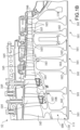
- high-pressure compressor 52 of the compressor section 24 of gas turbine engine 20 is provided.
- the high-pressure compressor 52 includes a plurality of blade stages 101 (i.e., rotor stages) and a plurality of vane stages 105 (i.e., stator stages).
- the blade stages 101 may each include an integrally bladed rotor ("IBR") 100, such that the blades 103 and rotor disks 102 are formed from a single integral component (i.e., a monolithic component formed of a single piece).
- IBR integrally bladed rotor
- the present disclosure is not limited in this regard.
- the inspection, analysis, and repair systems disclosed herein may be utilized with bladed rotors formed of separate blades 103 and rotor disks 102 and still be within the scope of this disclosure.
- the blades 103 extend radially outward from the rotor disk 102.
- the gas turbine engine 20 may further include an exit guide vane stage 106 that defines the aft end of the high-pressure compressor 52.
- the low-pressure compressor 44 may include a plurality of blade stages 101 and vane stages 105, each blade stage in the plurality of blade stages 101 including the IBR 100 and still be within the scope of this disclosure.
- the plurality of blade stages 101 form a stack of IBRs 110, which define, at least partially, a rotor module 111 of the high-pressure compressor 52 of the gas turbine engine 20.
- the debris When debris is ingested into the gas turbine engine 20, the debris may pass into the primary flow path. Due to the rotation of the blades 103 in the primary flow path, the debris may contact one or more of the blades 103. This contact may cause damage either foreign object damage (FOD) or domestic object damage (DOD) damage to a blade 103 or a set of the blades 103.
- FOD foreign object damage
- DOD domestic object damage
- Disclosed herein are systems and methods for inspection to identifying both visual and non-visual metallurgy, cracks, erosion, or geometric variation, among others, defects of an IBR 100. The systems and methods disclosed herein facilitate both visual (surface) damage, i.e.
- the systems and methods disclosed herein provide an inspection system to detect both visual and non-visual defects to and within the blades of the IBR via ports in the assembled gas turbine engine, in accordance with various embodiments.
- the size and shape of the defects 140 illustrated in FIG. 3 are exaggerated for illustrative effect. Further, the defects 140 may extend to all the blades 103 of the IBR 100, the rotor disk 102, a set of the blades 103 of the IBR 100, a single blade in the blades 103, or the like.
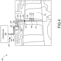
- the system 400 comprises a controller 402 and an inspection device 404.
- a proximal end of the inspection device is mechanically, electrically, and/or communicatively coupled to the controller 402.
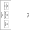
- the controller 402 includes a processor 502, a memory 504, and a user interface 506 for controlling the inspection device 404, i.e. controlling various components of the inspection device 404 in order to inspect blade 103 of the IBR.
- the processor 502 may be a general-purpose processor, a digital signal processor (DSP), an application specific integrated circuit (ASIC), a field programable gate array (FPGA) or other programable logic device, discrete gate or transistor logic, discrete hardware components, or any combination thereof.
- DSP digital signal processor
- ASIC application specific integrated circuit
- FPGA field programable gate array
- the processor 502 may be configured to implement various logical operations in response to an execution of instructions, for example, instructions stored in memory 504 which is a non-transitory, tangible, computer-readable medium configured to communicate with processor 502.
- System program instructions and/or controller instructions may be loaded onto a non-transitory, tangible computer-readable medium having instructions stored thereon that, in response to execution by the processor 502, cause the processor 502 to perform various operations.
- the term "non-transitory” is to be understood to remove only propagating transitory signals per se from the claim scope and does not relinquish rights to all standard computer-readable media that are not only propagating transitory signals per se. Stated another way, the meaning of the term “non-transitory computer-readable medium” and “non-transitory computer-readable storage medium” should be construed to exclude only those types of transitory computer-readable media which were found in In Re Nuijten to fall outside the scope of patentable subject matter under 35 U.S.C. ⁇ 101.
- the controller 402 responsive to receiving input via user interface 506, the controller 402 is configured to send one or more commands to the various components of the inspection device 404 for inspection of the blade 103.
- the inspection device 404 includes a plurality of configurable segments 406 that operate in either a flexible or rigid manner thereby forming a flexible shaft, a probe 408 including a plurality of signal generators 410, a signal receiver 412, and a positioning assistant 414.
- the controller 402 may be configured to snake a distal end of the inspection device 404 through a port 416 on an inner case of the gas turbine engine into an area where an inspection of the leading edge of the blade 103 of the IBR may be inspected thereby providing an in-situ engine inspection.
- the controller 402 may be configured to configure each of the plurality of configurable segments 406 in order to position the distal end of the inspection device 404 into a position associated with the blade 103 using sensors included within the positioning assistant 414.
- the distal end of the inspection device 404 may have various end effectors with a common adaptor plate to adapt to different inspection locations.
- the position may be in proximity to a leading edge, a trailing edge, or one of the sides of the blade 103.
- the positioning assistant 414 may include sensor(s) such as Hall effect sensor(s), optical sensor(s), resolver(s), among others.
- the positioning assistant 414 may include sensor(s) configured to detect an angular position of the distal end of the inspection device 404 during inspection of the blade 103.
- the controller 402 receives sensor data from the positioning assistant 414.
- the controller 402 may utilize the sensor data received from the positioning assistant 414 to correlate an angular position of the blade 103 being inspected.
- the blade 103 may remain stationary throughout an inspection process and only the inspection device 404 may move. Thus, coordinates of the inspection device 404 may be determined via sensor(s) in the positioning assistant 414 to inspect the blade 103.
- the controller 402 is configured to send one or more commands to the probe 408 to inspect the blade 103 using the plurality of signal generators 410 and the signal receiver 412.
- the plurality of signal generators 410 responsive to receiving the command, in various embodiments, generates signal waves that bounce off one or more surfaces of the blade 103 and are received by the signal receiver 412 thereby identifying visual (surface) damage data, i.e. surface metallurgy, cracks, erosion, or geometric variation, among others, in a line of sight of the blade 103 of the IBR.
- the plurality of signal generators 410 responsive to receiving the command, in various embodiments, the plurality of signal generators 410 generates signal waves that penetrate one or more surfaces of the blade 103 which then rebound and are received by the signal receiver 412 thereby identifying non-visual (subsurface) damage data, i.e. subsurface metallurgy, cracks, erosion, or geometric variation, among others, beyond line of sight.
- non-visual (subsurface) damage data i.e. subsurface metallurgy, cracks, erosion, or geometric variation, among others, beyond line of sight.
- the signal receiver 412 routes the received signals to the controller 402.
- the controller 402 may then apply nondestructive examination (NDE) methods such as vibrational resonance or process compensated resonance testing (PCRT), which is pattern recognition to the entire spectra of the blade 103 to determine whether the blade 103 includes a defect.
- NDE nondestructive examination
- PCT process compensated resonance testing
- the controller 402 may also produce images of the blade 103 via user interface 506.
- the PCRT inspection process provides an enhanced ability to detect both visual (surface) damage, i.e. surface metallurgy, cracks, erosion, or geometric variation, among others, in a line of sight, and non-visual (subsurface) damage, i.e. subsurface metallurgy, cracks, erosion, or geometric variation, among others, beyond line of sight.
- visual damage i.e. surface metallurgy, cracks, erosion, or geometric variation, among others
- non-visual (subsurface) damage i.e. subsurface metallurgy, cracks, erosion, or geometric variation, among others.
- references to "one embodiment,” “an embodiment,” “an example embodiment,” etc. indicate that the embodiment described may include a particular feature, structure, or characteristic, but every embodiment may not necessarily include the particular feature, structure, or characteristic. Moreover, such phrases are not necessarily referring to the same embodiment. Further, when a particular feature, structure, or characteristic is described in connection with an embodiment, it is submitted that it is within the knowledge of one skilled in the art to affect such feature, structure, or characteristic in connection with other embodiments whether or not explicitly described. After reading the description, it will be apparent to one skilled in the relevant art(s) how to implement the disclosure in alternative embodiments.
Landscapes
- Physics & Mathematics (AREA)
- Biochemistry (AREA)
- General Physics & Mathematics (AREA)
- Life Sciences & Earth Sciences (AREA)
- Chemical & Material Sciences (AREA)
- Analytical Chemistry (AREA)
- Pathology (AREA)
- General Health & Medical Sciences (AREA)
- Health & Medical Sciences (AREA)
- Immunology (AREA)
- Engineering & Computer Science (AREA)
- Acoustics & Sound (AREA)
- Mechanical Engineering (AREA)
- General Engineering & Computer Science (AREA)
- Testing Of Devices, Machine Parts, Or Other Structures Thereof (AREA)
Applications Claiming Priority (1)
| Application Number | Priority Date | Filing Date | Title |
|---|---|---|---|
| US18/352,911 US20250020557A1 (en) | 2023-07-14 | 2023-07-14 | In situ engine airfoil process compensated resonance testing |
Publications (1)
| Publication Number | Publication Date |
|---|---|
| EP4497913A1 true EP4497913A1 (de) | 2025-01-29 |
Family
ID=91923726
Family Applications (1)
| Application Number | Title | Priority Date | Filing Date |
|---|---|---|---|
| EP24188087.1A Pending EP4497913A1 (de) | 2023-07-14 | 2024-07-11 | In-situ-motorschaufelprozesskompensierte resonanzprüfung |
Country Status (2)
| Country | Link |
|---|---|
| US (1) | US20250020557A1 (de) |
| EP (1) | EP4497913A1 (de) |
Citations (3)
| Publication number | Priority date | Publication date | Assignee | Title |
|---|---|---|---|---|
| US9027404B2 (en) * | 2012-05-17 | 2015-05-12 | Honeywell International Inc. | Ultrasonic non-destructive evaluation methods for friction-welded blisks |
| US9157788B2 (en) * | 2011-06-20 | 2015-10-13 | Vibrant Corporation | Part evaluation system/method using both resonance and surface vibration data |
| US20220236197A1 (en) * | 2021-01-28 | 2022-07-28 | General Electric Company | Inspection assistant for aiding visual inspections of machines |
-
2023
- 2023-07-14 US US18/352,911 patent/US20250020557A1/en active Pending
-
2024
- 2024-07-11 EP EP24188087.1A patent/EP4497913A1/de active Pending
Patent Citations (3)
| Publication number | Priority date | Publication date | Assignee | Title |
|---|---|---|---|---|
| US9157788B2 (en) * | 2011-06-20 | 2015-10-13 | Vibrant Corporation | Part evaluation system/method using both resonance and surface vibration data |
| US9027404B2 (en) * | 2012-05-17 | 2015-05-12 | Honeywell International Inc. | Ultrasonic non-destructive evaluation methods for friction-welded blisks |
| US20220236197A1 (en) * | 2021-01-28 | 2022-07-28 | General Electric Company | Inspection assistant for aiding visual inspections of machines |
Also Published As
| Publication number | Publication date |
|---|---|
| US20250020557A1 (en) | 2025-01-16 |
Similar Documents
| Publication | Publication Date | Title |
|---|---|---|
| EP3361229B1 (de) | System und verfahren zur rotorblattüberwachung | |
| US10822997B2 (en) | Inspection tool and method | |
| EP2870346B1 (de) | Erkennung eines erweiterten spitzentaktmessungsmodus einer schaufel | |
| EP3182102B1 (de) | System und verfahren zum prüfen von turbinenschaufeln | |
| US10196927B2 (en) | System and method for locating a probe within a gas turbine engine | |
| EP1312766B1 (de) | Einrichtung und Methode zur Entdeckung einer beschädigten Rotorschaufel | |
| CN115014780A (zh) | 用于燃气涡轮发动机构件的测量扭曲的可检测数据标记 | |
| US20230314281A1 (en) | Methods and systems of monitoring a condition of a component of a gas turbine engine | |
| US11156455B2 (en) | System and method for measuring clearance gaps between rotating and stationary components of a turbomachine | |
| EP3623788B1 (de) | Automatisiertes notrangordnungssystem | |
| EP4040101B1 (de) | Systeme und verfahren für pseudotriaxiale kapazitätssondenanordnungen | |
| US10196922B2 (en) | System and method for locating a probe within a gas turbine engine | |
| EP4497913A1 (de) | In-situ-motorschaufelprozesskompensierte resonanzprüfung | |
| US12209997B2 (en) | Inspection systems and methods for sealing surfaces | |
| EP3748134B1 (de) | Schaufelblattprofile für eingebettete elemente | |
| EP4276276A1 (de) | Verfahren zur visuellen inspektion von schaufelspitzen eines beschaufelten rotors | |
| EP4563788A1 (de) | Verfahren und system zur inspektion von gebläseturbinenschaufeln | |
| US12468869B2 (en) | Inspection systems and methods with airfoil sheaths | |
| US20250020558A1 (en) | Localized Rework Using Powder be Fusion Generated Segments | |
| EP4597096A2 (de) | Zerstörungsfreies prüfverfahren zur bauteilprüfung | |
| EP4400693A1 (de) | Rechnerischer ausgleich einer rotierenden struktur | |
| EP4667923A1 (de) | Inspektionssystem zur erkennung von oberflächenrissen mittels wirbelstromthermografie | |
| EP4617476A2 (de) | In einem einlasssondenkörper eingebettetes optisches inspektionssystem |
Legal Events
| Date | Code | Title | Description |
|---|---|---|---|
| PUAI | Public reference made under article 153(3) epc to a published international application that has entered the european phase |
Free format text: ORIGINAL CODE: 0009012 |
|
| STAA | Information on the status of an ep patent application or granted ep patent |
Free format text: STATUS: THE APPLICATION HAS BEEN PUBLISHED |
|
| AK | Designated contracting states |
Kind code of ref document: A1 Designated state(s): AL AT BE BG CH CY CZ DE DK EE ES FI FR GB GR HR HU IE IS IT LI LT LU LV MC ME MK MT NL NO PL PT RO RS SE SI SK SM TR |
|
| STAA | Information on the status of an ep patent application or granted ep patent |
Free format text: STATUS: REQUEST FOR EXAMINATION WAS MADE |
|
| 17P | Request for examination filed |
Effective date: 20250724 |