EP4498072A1 - Procédé et dispositif d'inspection d'au moins une surface extérieure de récipients - Google Patents
Procédé et dispositif d'inspection d'au moins une surface extérieure de récipients Download PDFInfo
- Publication number
- EP4498072A1 EP4498072A1 EP24166622.1A EP24166622A EP4498072A1 EP 4498072 A1 EP4498072 A1 EP 4498072A1 EP 24166622 A EP24166622 A EP 24166622A EP 4498072 A1 EP4498072 A1 EP 4498072A1
- Authority
- EP
- European Patent Office
- Prior art keywords
- container
- inspected
- image capture
- capture device
- alignment
- Prior art date
- Legal status (The legal status is an assumption and is not a legal conclusion. Google has not performed a legal analysis and makes no representation as to the accuracy of the status listed.)
- Pending
Links
Images
Classifications
-
- G—PHYSICS
- G01—MEASURING; TESTING
- G01N—INVESTIGATING OR ANALYSING MATERIALS BY DETERMINING THEIR CHEMICAL OR PHYSICAL PROPERTIES
- G01N21/00—Investigating or analysing materials by the use of optical means, i.e. using sub-millimetre waves, infrared, visible or ultraviolet light
- G01N21/84—Systems specially adapted for particular applications
- G01N21/88—Investigating the presence of flaws or contamination
- G01N21/90—Investigating the presence of flaws or contamination in a container or its contents
-
- G—PHYSICS
- G01—MEASURING; TESTING
- G01N—INVESTIGATING OR ANALYSING MATERIALS BY DETERMINING THEIR CHEMICAL OR PHYSICAL PROPERTIES
- G01N21/00—Investigating or analysing materials by the use of optical means, i.e. using sub-millimetre waves, infrared, visible or ultraviolet light
- G01N21/84—Systems specially adapted for particular applications
- G01N21/88—Investigating the presence of flaws or contamination
- G01N21/95—Investigating the presence of flaws or contamination characterised by the material or shape of the object to be examined
- G01N21/952—Inspecting the exterior surface of cylindrical bodies or wires
-
- G—PHYSICS
- G01—MEASURING; TESTING
- G01N—INVESTIGATING OR ANALYSING MATERIALS BY DETERMINING THEIR CHEMICAL OR PHYSICAL PROPERTIES
- G01N21/00—Investigating or analysing materials by the use of optical means, i.e. using sub-millimetre waves, infrared, visible or ultraviolet light
- G01N21/84—Systems specially adapted for particular applications
- G01N2021/8411—Application to online plant, process monitoring
-
- G—PHYSICS
- G01—MEASURING; TESTING
- G01N—INVESTIGATING OR ANALYSING MATERIALS BY DETERMINING THEIR CHEMICAL OR PHYSICAL PROPERTIES
- G01N21/00—Investigating or analysing materials by the use of optical means, i.e. using sub-millimetre waves, infrared, visible or ultraviolet light
- G01N21/84—Systems specially adapted for particular applications
- G01N2021/845—Objects on a conveyor
-
- G—PHYSICS
- G01—MEASURING; TESTING
- G01N—INVESTIGATING OR ANALYSING MATERIALS BY DETERMINING THEIR CHEMICAL OR PHYSICAL PROPERTIES
- G01N21/00—Investigating or analysing materials by the use of optical means, i.e. using sub-millimetre waves, infrared, visible or ultraviolet light
- G01N21/84—Systems specially adapted for particular applications
- G01N21/88—Investigating the presence of flaws or contamination
- G01N21/90—Investigating the presence of flaws or contamination in a container or its contents
- G01N21/909—Investigating the presence of flaws or contamination in a container or its contents in opaque containers or opaque container parts, e.g. cans, tins, caps, labels
Definitions
- the invention relates to a device for inspecting at least one outer surface of containers.
- the invention relates to a method for inspecting at least one outer surface of containers.
- Containers within the meaning of this document can be, for example, cans or bottles.
- the containers are first manufactured as such and then often provided with a decoration that is printed on the outer surface of the container or applied to it as a label.
- the tin can is transported upright on a conveyor belt to the next production process.
- photos are taken of the outside using several industrial cameras nearby.
- the individual images captured by the industrial cameras are then combined in software and the complete image of the decoration is checked for defects.
- the parameterization of the software for correctly combining the individual images to form the overall image is complex, computationally intensive and error-prone. Small surface defects, for example on the decoration of a can, cannot be detected with sufficient certainty. The inspection result that can be achieved using the known devices and methods is therefore not satisfactory overall for the requirements of the market.
- the detection device for detecting the orientation of a container to be inspected is designed to detect the container orientation based on the position determination of at least one container feature.
- the detection device for detecting the orientation of a container to be inspected has at least one camera.
- the at least one camera is equipped with a wide-angle lens.
- the at least one camera of the detection device for detecting the orientation of a container to be inspected is designed as a color matrix camera with a resolution of at least 1.3 MP.
- the detection device for detecting the orientation of a container to be inspected has at least one lighting device.
- the at least one camera of the detection device for detecting the orientation of a container to be inspected is arranged above the container to be inspected and is aligned such that the camera focus is directed from above onto and/or into the container. This is particularly advantageous with regard to containers to be inspected, such as cans or bottles, in which the outer surface to be inspected is completely or partially covered by the decoration or the label.
- the detection device is designed to detect the orientation of a container to be inspected in order to determine the position of at least one weld seam of the container.
- an alignment deviation can be determined automatically.
- the alignment system is designed to align the container depending on the determined alignment deviation.
- the alignment system preferably has at least one rotating element with which the container can be rotated from the determined alignment to the desired alignment.
- the alignment system comprises two conveyor belts with their support surfaces opposite each other and aligned approximately parallel to each other, which are arranged at a distance from each other that is slightly smaller than the Diameter of the container to be inspected.
- the conveyor belts are designed to contact the outer surface to be inspected with respect to a can of the outer surface in such a way that the container to be inspected can be rotated by a different speed of the two conveyor belts.
- the distance between the conveyor belts corresponds to the diameter of the containers to be inspected minus about 1 to 5 mm, particularly preferably minus about 2 mm.
- the conveyor belts can be controlled or driven in opposite directions such that the container can be rotated into the desired orientation in order to correct the alignment deviation.
- the conveyor belts are rubberized.
- the at least one image capture device for capturing the at least one outer surface of the container to be inspected has at least one imaging capture device, preferably at least one camera, for capturing the outer surface of the container to be inspected.
- the image capture device has more than one imaging capture device.
- the image capture device preferably has at least three imaging detection devices, which are particularly preferably arranged at equal angular intervals, in the case of three imaging detection devices at an angle rotated by 120° to one another.
- the image capture device is divided into at least two stations, wherein at least one, preferably at least two imaging capture devices are arranged in each station.
- the imaging detection devices are arranged opposite one another in the stations of the image detection device.
- an alignment system is arranged between each station of the image capture device, with which the container to be inspected can be rotated into the respective desired alignment for the following station of the image capture device.
- the device for inspecting at least one outer surface of containers has three stations of the image capture device arranged one behind the other, wherein an alignment system is arranged in front of each of the stations of the image capture device.
- the image capture device preferably has at least one illumination device, preferably at least one illumination device for each imaging capture device.
- the image capture device has at least two illumination devices per imaging capture device, each of which is directed laterally towards the container to be inspected when the container is in the focus of the respective imaging capture device.
- the at least two illumination devices assigned to each imaging detection device are arranged such that the containers to be inspected can be illuminated synchronously and in reverse in the focus of the respective imaging detection device.
- the imaging detection devices are arranged in at least one detection chamber through which the container to be inspected can be transported.
- detection chambers enables the reduction of external influences on the captured images of the containers to be inspected and thus a more reliable inspection.
- one capture chamber is preferably provided per station.
- the image capture device in advantageous embodiments of the invention preferably has at least one wall element for forming a defined homogeneous background, arranged opposite the at least one imaging detection device.
- the background is designed in terms of colour and/or brightness so that it has a high contrast to the container to be inspected.
- the background is matte.
- the device for inspecting at least one outer surface of containers has at least one evaluation unit for automatically evaluating the recorded images and for automatically comparing the recorded images with reference images.
- a faulty container can be automatically identified with the aid of the evaluation unit, so that faulty containers can be automatically sorted out in embodiments of the invention and/or a corresponding output can be generated for the personnel.
- the device according to the invention for inspecting at least one outer surface of containers has at least one transport device for transporting the containers to be inspected between and/or in the detection device for detecting the orientation of a container to be inspected, the alignment system for the defined orientation of a container to be inspected and the image capture device for detecting the at least one outer surface of the container to be inspected.
- the transport device is realized by at least one conveyor belt.
- the imaging capture devices are preferably arranged and aligned such that the transport device is outside the capture range of the imaging capture devices. This at least significantly reduces the influence of the conveyor belt, which may be inhomogeneous due to wear and/or contamination, on the image to be inspected.
- the outer wall of the container to be inspected is captured in at least two stations of the image capture device one after the other, wherein the container to be inspected is brought into a predetermined target orientation before each station of the image capture device.
- the outer wall of the container to be inspected is captured in three stations of the image capture device one after the other, with the container to be inspected being brought into a predetermined target orientation before each station of the image capture device.
- the container to be inspected is rotated further by 60° in the same direction after the first and second stations of the image capture device.
- images of the outer surface to be inspected are recorded, preferably by imaging capture devices arranged opposite one another, for example cameras, between which the container to be inspected is guided in the middle. If an angle range of 60° is defined as the image area to be evaluated, the recording of images of the container to be inspected results in A complete circumferential (360°) image of the outer surface to be inspected is created from a total of six views, each with an angular range of 60° to be evaluated.
- the images of the individual views of the container to be inspected are directly compared with reference images of the same view. This means that it is no longer necessary to combine the individual views into an overall view and enables simpler and more reliable image evaluation for the container inspection.
- the containers are transported continuously in the conveying direction without stopping. This enables integration into systems with high production speeds without this being affected by the inspection.
- a device according to the invention is used for inspecting the outer surfaces of containers.
- small decorative defects in the order of about 1 mm 2 can be detected reliably and with little parameterization effort using the device according to the invention and/or the method according to the invention.
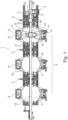
- FIG. 1 a top view of a section through a device (1) according to the invention for inspecting at least one outer surface of containers (20) is shown.
- the inspection device (1) comprises a detection device (2) for detecting the orientation of a container (20) to be inspected using a container feature (21), an alignment system (3) and an image capture device (4) comprising three stations (6).
- the device (1) has a transport device (13) designed as a conveyor belt.
- An alignment system (3) is arranged in the conveying direction in front of each of the stations (6) of the image capture device (4) in order to bring the container (20) to be inspected into the predetermined target alignment for the respective image capture.
- the alignment system (3) has two rotating elements (5) designed as conveyor belts, with which a container (20) can be rotated about a vertical axis of rotation while it is being transported on the transport device (13).
- the conveyor belts are aligned with a conveying direction parallel to the transport device (13) but positioned vertically, so that the conveyor belts contact the side wall of the container (20) being transported upright.
- Each of the stations (6) of the image capture device (4) has a capture chamber (7) which is delimited on the outside by a housing.
- imaging capture devices (8) designed as cameras are arranged on opposite sides next to the conveyor belt, as well as two associated lighting devices (9) for each imaging capture device (8).
- the imaging detection devices (8) are integrated into wall elements (10) or arranged behind them.
- the wall elements (10) are shaped like tube segments and serve to create a homogeneous background for image capture.
- the lighting devices (9) are arranged in the region of the ends of the wall elements (10) facing the transport device (13) and are directed towards the container (20) to be inspected, which is located in the focus of the imaging detection devices (8).
- the imaging detection devices (8) each have a defined evaluable angular range (12) of 60°.
- a beam splitter (11) is arranged in the area of each imaging detection device (8).
- the beam splitter (11) prevents the imaging detection device (8), for example a camera, from "seeing" itself, but rather a homogeneous background generated by the beam splitter (11) itself, which is the same as the rest of the background.
- the opposing lighting devices (9) create a homogeneous background for the imaging detection device (8).
- the distance between the lighting devices (9) results from the viewing angle of the imaging detection device (8) and the curvature of the test object being considered.
- the aim is that the lighting devices (9), the imaging detection device (8) and other interference variables do not appear in the mirror image of the test object.
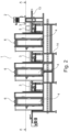
- Figure 2 shows the same embodiment of the device (1) according to the invention for inspecting outer surfaces of containers in a side view, wherein the sectional plane AA for the Figure 1 shown view is drawn.
- the previously described elements of the device (1) are arranged on a frame construction (14).
Landscapes
- Physics & Mathematics (AREA)
- Health & Medical Sciences (AREA)
- Life Sciences & Earth Sciences (AREA)
- Chemical & Material Sciences (AREA)
- Analytical Chemistry (AREA)
- Biochemistry (AREA)
- General Health & Medical Sciences (AREA)
- General Physics & Mathematics (AREA)
- Immunology (AREA)
- Pathology (AREA)
- Investigating Materials By The Use Of Optical Means Adapted For Particular Applications (AREA)
Applications Claiming Priority (1)
| Application Number | Priority Date | Filing Date | Title |
|---|---|---|---|
| DE102023119491.7A DE102023119491A1 (de) | 2023-07-24 | 2023-07-24 | Verfahren und Vorrichtung zur Inspektion mindestens einer Außenfläche von Behältern |
Publications (1)
| Publication Number | Publication Date |
|---|---|
| EP4498072A1 true EP4498072A1 (fr) | 2025-01-29 |
Family
ID=90675206
Family Applications (1)
| Application Number | Title | Priority Date | Filing Date |
|---|---|---|---|
| EP24166622.1A Pending EP4498072A1 (fr) | 2023-07-24 | 2024-03-27 | Procédé et dispositif d'inspection d'au moins une surface extérieure de récipients |
Country Status (2)
| Country | Link |
|---|---|
| EP (1) | EP4498072A1 (fr) |
| DE (1) | DE102023119491A1 (fr) |
Citations (5)
| Publication number | Priority date | Publication date | Assignee | Title |
|---|---|---|---|---|
| US4691231A (en) * | 1985-10-01 | 1987-09-01 | Vistech Corporation | Bottle inspection system |
| EP0872724A2 (fr) * | 1997-03-18 | 1998-10-21 | Logics & Control S.n.c. di Lottici Marco e C. | Procédé et dispositif de contrÔle extérieur de récipients |
| DE69919297T2 (de) * | 1998-10-22 | 2004-12-23 | O.M.S.O. S.P.A. | Automatische Vorrichtung zur Bestimmung der Druckqualität auf Flaschen beliebiger Form |
| JP2005345423A (ja) * | 2004-06-07 | 2005-12-15 | Asahi Breweries Ltd | 容器検査装置 |
| WO2021198797A1 (fr) * | 2020-03-31 | 2021-10-07 | Makro Labelling S.R.L. | Machine d'inspection de récipients |
Family Cites Families (4)
| Publication number | Priority date | Publication date | Assignee | Title |
|---|---|---|---|---|
| DE102005050902A1 (de) | 2005-10-21 | 2007-05-03 | Khs Ag | Vorrichtung zum Ausrichten von Behältern sowie Etikettiermaschine mit einer solchen Vorrichtung |
| DE102008059229A1 (de) | 2008-11-20 | 2010-06-02 | Khs Ag | Verfahren zum Ausrichten eines Behälters |
| DE102018107305A1 (de) | 2018-03-27 | 2019-10-02 | Krones Ag | Vorrichtung und Verfahren zur optischen Positionserkennung transportierter Objekte |
| BR112022006254A2 (pt) | 2019-10-01 | 2022-06-21 | Antares Vision S P A | Dispositivo e processo para a orientação de recipientes |
-
2023
- 2023-07-24 DE DE102023119491.7A patent/DE102023119491A1/de active Pending
-
2024
- 2024-03-27 EP EP24166622.1A patent/EP4498072A1/fr active Pending
Patent Citations (5)
| Publication number | Priority date | Publication date | Assignee | Title |
|---|---|---|---|---|
| US4691231A (en) * | 1985-10-01 | 1987-09-01 | Vistech Corporation | Bottle inspection system |
| EP0872724A2 (fr) * | 1997-03-18 | 1998-10-21 | Logics & Control S.n.c. di Lottici Marco e C. | Procédé et dispositif de contrÔle extérieur de récipients |
| DE69919297T2 (de) * | 1998-10-22 | 2004-12-23 | O.M.S.O. S.P.A. | Automatische Vorrichtung zur Bestimmung der Druckqualität auf Flaschen beliebiger Form |
| JP2005345423A (ja) * | 2004-06-07 | 2005-12-15 | Asahi Breweries Ltd | 容器検査装置 |
| WO2021198797A1 (fr) * | 2020-03-31 | 2021-10-07 | Makro Labelling S.R.L. | Machine d'inspection de récipients |
Also Published As
| Publication number | Publication date |
|---|---|
| DE102023119491A1 (de) | 2025-01-30 |
Similar Documents
| Publication | Publication Date | Title |
|---|---|---|
| EP2598861B1 (fr) | Dispositif d'inspection, installation de fabrication équipée d'un dispositif d'inspection et procédé d'inspection de récipients | |
| DE2617457C3 (de) | Vorrichtung zum Prüfen von durchsichtigen, axial symmetrischen Gegenständen auf Fehler | |
| DE2938235C2 (fr) | ||
| DE69525195T2 (de) | Optische Inspektion von Dimensionsparametern von Behältern | |
| DE68926830T2 (de) | Verfahren und Vorrichtung zur Prüfung der Seitenwand einer Flasche | |
| EP1130384A1 (fr) | Machine de contrôle | |
| EP0657732A1 (fr) | Méthode et appareil d'inspection optique d'une zone transparente d'un récipient, notamment le goulot | |
| DE3906281A1 (de) | Verfahren und vorrichtung zum optischen ueberpruefen des aussehens chipartiger bauteile und zum sortieren der chipartigen bauteile | |
| DE102018202051B4 (de) | Vorrichtung zum automatischen Prüfen von Linsen und Verfahren zum automatischen Prüfen einer Vielzahl von Linsen | |
| DE19708582A1 (de) | Qualitätskontrolle für Kunststeine | |
| DE3111194C2 (de) | Verfahren und Vorrichtung zur Feststellung von Fehlern von Glasgegenständen | |
| DE3809221A1 (de) | Verfahren zum detektieren von fehlstellen an pressteilen oder anderen werkstuecken und vorrichtung zur durchfuehrung des verfahrens | |
| DE102007018870A1 (de) | Inspektionsvorrichtung zum Untersuchen von Behältnisverschlüssen | |
| DE102016209722A1 (de) | Vorrichtung und Verfahren zur Inspektion von Behältnissen | |
| EP1826557B2 (fr) | Contrôle optique de produits de l'industrie du traitement du tabac | |
| EP0708325A1 (fr) | Méthode et dispositif d'inspection d'objets notamment de bouteilles | |
| EP4033227A1 (fr) | Procédé de détection optique de défauts des articles en céramique | |
| DE102021109286A1 (de) | Verfahren und Vorrichtung zum Inspizieren von Behältnissen mit Feststellung einer Drehstellung eines Behältnisverschlusses | |
| DE102006008840A1 (de) | Beleuchtungsvorrichtung für zylindrische Objekte, damit durchgeführtes Oberflächenuntersuchungsverfahren und Computerprogrammprodukt | |
| EP1419375A1 (fr) | Procede et dispositif de controle de bouteilles fermees et remplies, en particulier dans la zone de la paroi laterale desdites bouteilles situee a proximite du fond | |
| EP4498072A1 (fr) | Procédé et dispositif d'inspection d'au moins une surface extérieure de récipients | |
| EP0987541B1 (fr) | Dispositif de contrôle optique de qualité de la surface interne d'un tube | |
| CH697954B1 (de) | Verfahren und Vorrichtung zur Werkstückprüfung und/oder -kontrolle. | |
| DE19634881C1 (de) | Optische Prüfvorrichtung | |
| DE202004020330U1 (de) | Vorrichtung zur Überprüfung von Randbereichen flächiger Elemente |
Legal Events
| Date | Code | Title | Description |
|---|---|---|---|
| PUAI | Public reference made under article 153(3) epc to a published international application that has entered the european phase |
Free format text: ORIGINAL CODE: 0009012 |
|
| STAA | Information on the status of an ep patent application or granted ep patent |
Free format text: STATUS: THE APPLICATION HAS BEEN PUBLISHED |
|
| AK | Designated contracting states |
Kind code of ref document: A1 Designated state(s): AL AT BE BG CH CY CZ DE DK EE ES FI FR GB GR HR HU IE IS IT LI LT LU LV MC ME MK MT NL NO PL PT RO RS SE SI SK SM TR |
|
| STAA | Information on the status of an ep patent application or granted ep patent |
Free format text: STATUS: REQUEST FOR EXAMINATION WAS MADE |
|
| 17P | Request for examination filed |
Effective date: 20250703 |