EP4498568A1 - Procédé et appareil de commande de circuit de charge et de décharge, système, dispositif et support de stockage - Google Patents
Procédé et appareil de commande de circuit de charge et de décharge, système, dispositif et support de stockage Download PDFInfo
- Publication number
- EP4498568A1 EP4498568A1 EP23790892.6A EP23790892A EP4498568A1 EP 4498568 A1 EP4498568 A1 EP 4498568A1 EP 23790892 A EP23790892 A EP 23790892A EP 4498568 A1 EP4498568 A1 EP 4498568A1
- Authority
- EP
- European Patent Office
- Prior art keywords
- charge
- current
- current value
- discharge
- values
- Prior art date
- Legal status (The legal status is an assumption and is not a legal conclusion. Google has not performed a legal analysis and makes no representation as to the accuracy of the status listed.)
- Pending
Links
Images

Classifications
-
- H—ELECTRICITY
- H02—GENERATION; CONVERSION OR DISTRIBUTION OF ELECTRIC POWER
- H02J—ELECTRIC POWER NETWORKS; CIRCUIT ARRANGEMENTS OR SYSTEMS FOR SUPPLYING OR DISTRIBUTING ELECTRIC POWER; SYSTEMS FOR STORING ELECTRIC ENERGY
- H02J7/00—Circuit arrangements for charging or discharging batteries or for supplying loads from batteries
- H02J7/14—Circuit arrangements for charging or discharging batteries or for supplying loads from batteries for charging batteries from dynamo-electric generators driven at varying speed, e.g. on vehicle
-
- H—ELECTRICITY
- H02—GENERATION; CONVERSION OR DISTRIBUTION OF ELECTRIC POWER
- H02J—ELECTRIC POWER NETWORKS; CIRCUIT ARRANGEMENTS OR SYSTEMS FOR SUPPLYING OR DISTRIBUTING ELECTRIC POWER; SYSTEMS FOR STORING ELECTRIC ENERGY
- H02J7/00—Circuit arrangements for charging or discharging batteries or for supplying loads from batteries
- H02J7/90—Regulation of charging or discharging current or voltage
- H02J7/94—Regulation of charging or discharging current or voltage in response to battery current
-
- B—PERFORMING OPERATIONS; TRANSPORTING
- B60—VEHICLES IN GENERAL
- B60L—PROPULSION OF ELECTRICALLY-PROPELLED VEHICLES; SUPPLYING ELECTRIC POWER FOR AUXILIARY EQUIPMENT OF ELECTRICALLY-PROPELLED VEHICLES; ELECTRODYNAMIC BRAKE SYSTEMS FOR VEHICLES IN GENERAL; MAGNETIC SUSPENSION OR LEVITATION FOR VEHICLES; MONITORING OPERATING VARIABLES OF ELECTRICALLY-PROPELLED VEHICLES; ELECTRIC SAFETY DEVICES FOR ELECTRICALLY-PROPELLED VEHICLES
- B60L53/00—Methods of charging batteries, specially adapted for electric vehicles; Charging stations or on-board charging equipment therefor; Exchange of energy storage elements in electric vehicles
- B60L53/20—Methods of charging batteries, specially adapted for electric vehicles; Charging stations or on-board charging equipment therefor; Exchange of energy storage elements in electric vehicles characterised by converters located in the vehicle
- B60L53/24—Using the vehicle's propulsion converter for charging
-
- H—ELECTRICITY
- H01—ELECTRIC ELEMENTS
- H01M—PROCESSES OR MEANS, e.g. BATTERIES, FOR THE DIRECT CONVERSION OF CHEMICAL ENERGY INTO ELECTRICAL ENERGY
- H01M10/00—Secondary cells; Manufacture thereof
- H01M10/42—Methods or arrangements for servicing or maintenance of secondary cells or secondary half-cells
- H01M10/425—Structural combination with electronic components, e.g. electronic circuits integrated to the outside of the casing
-
- H—ELECTRICITY
- H01—ELECTRIC ELEMENTS
- H01M—PROCESSES OR MEANS, e.g. BATTERIES, FOR THE DIRECT CONVERSION OF CHEMICAL ENERGY INTO ELECTRICAL ENERGY
- H01M10/00—Secondary cells; Manufacture thereof
- H01M10/42—Methods or arrangements for servicing or maintenance of secondary cells or secondary half-cells
- H01M10/44—Methods for charging or discharging
-
- H—ELECTRICITY
- H01—ELECTRIC ELEMENTS
- H01M—PROCESSES OR MEANS, e.g. BATTERIES, FOR THE DIRECT CONVERSION OF CHEMICAL ENERGY INTO ELECTRICAL ENERGY
- H01M10/00—Secondary cells; Manufacture thereof
- H01M10/42—Methods or arrangements for servicing or maintenance of secondary cells or secondary half-cells
- H01M10/44—Methods for charging or discharging
- H01M10/443—Methods for charging or discharging in response to temperature
-
- H—ELECTRICITY
- H02—GENERATION; CONVERSION OR DISTRIBUTION OF ELECTRIC POWER
- H02J—ELECTRIC POWER NETWORKS; CIRCUIT ARRANGEMENTS OR SYSTEMS FOR SUPPLYING OR DISTRIBUTING ELECTRIC POWER; SYSTEMS FOR STORING ELECTRIC ENERGY
- H02J7/00—Circuit arrangements for charging or discharging batteries or for supplying loads from batteries
- H02J7/60—Circuit arrangements for charging or discharging batteries or for supplying loads from batteries including safety or protection arrangements
-
- H—ELECTRICITY
- H02—GENERATION; CONVERSION OR DISTRIBUTION OF ELECTRIC POWER
- H02J—ELECTRIC POWER NETWORKS; CIRCUIT ARRANGEMENTS OR SYSTEMS FOR SUPPLYING OR DISTRIBUTING ELECTRIC POWER; SYSTEMS FOR STORING ELECTRIC ENERGY
- H02J7/00—Circuit arrangements for charging or discharging batteries or for supplying loads from batteries
- H02J7/855—Circuit arrangements for charging or discharging batteries or for supplying loads from batteries with circuits adapted for supplying loads from the battery
-
- H—ELECTRICITY
- H02—GENERATION; CONVERSION OR DISTRIBUTION OF ELECTRIC POWER
- H02J—ELECTRIC POWER NETWORKS; CIRCUIT ARRANGEMENTS OR SYSTEMS FOR SUPPLYING OR DISTRIBUTING ELECTRIC POWER; SYSTEMS FOR STORING ELECTRIC ENERGY
- H02J7/00—Circuit arrangements for charging or discharging batteries or for supplying loads from batteries
- H02J7/90—Regulation of charging or discharging current or voltage
- H02J7/933—Regulation of charging or discharging current or voltage the cycle being controlled or terminated in response to electric parameters
-
- H—ELECTRICITY
- H02—GENERATION; CONVERSION OR DISTRIBUTION OF ELECTRIC POWER
- H02P—CONTROL OR REGULATION OF ELECTRIC MOTORS, ELECTRIC GENERATORS OR DYNAMO-ELECTRIC CONVERTERS; CONTROLLING TRANSFORMERS, REACTORS OR CHOKE COILS
- H02P29/00—Arrangements for regulating or controlling electric motors, appropriate for both AC and DC motors
- H02P29/02—Providing protection against overload without automatic interruption of supply
- H02P29/032—Preventing damage to the motor, e.g. setting individual current limits for different drive conditions
-
- H—ELECTRICITY
- H01—ELECTRIC ELEMENTS
- H01M—PROCESSES OR MEANS, e.g. BATTERIES, FOR THE DIRECT CONVERSION OF CHEMICAL ENERGY INTO ELECTRICAL ENERGY
- H01M10/00—Secondary cells; Manufacture thereof
- H01M10/42—Methods or arrangements for servicing or maintenance of secondary cells or secondary half-cells
- H01M10/425—Structural combination with electronic components, e.g. electronic circuits integrated to the outside of the casing
- H01M2010/4271—Battery management systems including electronic circuits, e.g. control of current or voltage to keep battery in healthy state, cell balancing
-
- H—ELECTRICITY
- H01—ELECTRIC ELEMENTS
- H01M—PROCESSES OR MEANS, e.g. BATTERIES, FOR THE DIRECT CONVERSION OF CHEMICAL ENERGY INTO ELECTRICAL ENERGY
- H01M10/00—Secondary cells; Manufacture thereof
- H01M10/42—Methods or arrangements for servicing or maintenance of secondary cells or secondary half-cells
- H01M10/425—Structural combination with electronic components, e.g. electronic circuits integrated to the outside of the casing
- H01M2010/4278—Systems for data transfer from batteries, e.g. transfer of battery parameters to a controller, data transferred between battery controller and main controller
-
- H—ELECTRICITY
- H02—GENERATION; CONVERSION OR DISTRIBUTION OF ELECTRIC POWER
- H02J—ELECTRIC POWER NETWORKS; CIRCUIT ARRANGEMENTS OR SYSTEMS FOR SUPPLYING OR DISTRIBUTING ELECTRIC POWER; SYSTEMS FOR STORING ELECTRIC ENERGY
- H02J2105/00—Networks for supplying or distributing electric power characterised by their spatial reach or by the load
- H02J2105/30—Networks for supplying or distributing electric power characterised by their spatial reach or by the load the load networks being external to vehicles, i.e. exchanging power with vehicles
- H02J2105/33—Networks for supplying or distributing electric power characterised by their spatial reach or by the load the load networks being external to vehicles, i.e. exchanging power with vehicles exchanging power with road vehicles
- H02J2105/37—Networks for supplying or distributing electric power characterised by their spatial reach or by the load the load networks being external to vehicles, i.e. exchanging power with vehicles exchanging power with road vehicles exchanging power with electric vehicles [EV] or with hybrid electric vehicles [HEV]
-
- H—ELECTRICITY
- H02—GENERATION; CONVERSION OR DISTRIBUTION OF ELECTRIC POWER
- H02J—ELECTRIC POWER NETWORKS; CIRCUIT ARRANGEMENTS OR SYSTEMS FOR SUPPLYING OR DISTRIBUTING ELECTRIC POWER; SYSTEMS FOR STORING ELECTRIC ENERGY
- H02J2207/00—Details of circuit arrangements for charging or discharging batteries or supplying loads from batteries
- H02J2207/20—Charging or discharging characterised by the power electronics converter
-
- H—ELECTRICITY
- H02—GENERATION; CONVERSION OR DISTRIBUTION OF ELECTRIC POWER
- H02J—ELECTRIC POWER NETWORKS; CIRCUIT ARRANGEMENTS OR SYSTEMS FOR SUPPLYING OR DISTRIBUTING ELECTRIC POWER; SYSTEMS FOR STORING ELECTRIC ENERGY
- H02J7/00—Circuit arrangements for charging or discharging batteries or for supplying loads from batteries
- H02J7/02—Circuit arrangements for charging or discharging batteries or for supplying loads from batteries for charging batteries from AC mains by converters
- H02J7/04—Regulation of charging current or voltage
- H02J7/06—Regulation of charging current or voltage using discharge tubes or semiconductor devices
-
- H—ELECTRICITY
- H02—GENERATION; CONVERSION OR DISTRIBUTION OF ELECTRIC POWER
- H02J—ELECTRIC POWER NETWORKS; CIRCUIT ARRANGEMENTS OR SYSTEMS FOR SUPPLYING OR DISTRIBUTING ELECTRIC POWER; SYSTEMS FOR STORING ELECTRIC ENERGY
- H02J7/00—Circuit arrangements for charging or discharging batteries or for supplying loads from batteries
- H02J7/90—Regulation of charging or discharging current or voltage
- H02J7/971—Regulation of charging or discharging current or voltage the charge cycle being controlled or terminated in response to non-electric parameters
- H02J7/975—Regulation of charging or discharging current or voltage the charge cycle being controlled or terminated in response to non-electric parameters in response to temperature
- H02J7/977—Regulation of charging or discharging current or voltage the charge cycle being controlled or terminated in response to non-electric parameters in response to temperature of the battery
Definitions
- a method for controlling a charge and discharge circuit where the charge and discharge circuit includes an M-phase motor winding, M being a positive integer.
- the method includes:
- the current values can be accurately and quickly acquired by detecting the current value flowing through the neutral line and the current values flowing through the windings by the current detection module.
- the determining whether a current charge and discharge state is normal according to the first current value and the second current values includes: if an absolute value of a difference between any two of the second current values is less than a first preset threshold, an absolute value of a difference between a sum of all the second current values and the first current value is less than a second preset threshold, the first current value is less than a third preset threshold, and each of the second current values is less than a fourth preset threshold, then determining the current charge and discharge state to be normal; otherwise, determining it to be abnormal.
- the determining whether a current charge and discharge state is normal according to the first current value and the second current values includes: if the absolute value of the difference between any two of the second current values is less than the first preset threshold, the first current value is less than the third preset threshold, and each of the second current values is less than the fourth preset threshold, then determining the current charge and discharge state to be normal; otherwise, determining it to be abnormal.
- the controlling the charge and discharge power to be reduced includes: controlling a charge and discharge cycle to be shortened to reduce the charge and discharge power. Controlling a charge and discharge cycle to be shortened to reduce the charge and discharge power allows easy operation.
- the controlling the charge and discharge power to be reduced includes:
- the second current values are all acquired through detection by the current detection module; and the acquiring a deviation degree of the first current value and the second current values from the preset normal state includes:
- one of the second current values is calculated according to the first current value and other second current values detected by the current detection module; and the acquiring a deviation degree of the first current value and the second current values from the preset normal state includes:
- the controlling the charge and discharge power to be reduced according to the deviation degree includes:
- the shortened time length of the charge and discharge cycle corresponding to the power reduction amplitude acquired through this step is relatively accurate, which helps to accurately control the charge and discharge cycle to be shortened according to the shortened time length.
- the present application provides an apparatus for controlling a charge and discharge circuit, where the charge and discharge circuit includes an M-phase motor winding, M being a positive integer.
- the method includes:
- the charge and discharge power is controlled to be reduced, thereby effectively reducing the safety hazards caused by abnormal current values and improving the safety of the charge and discharge circuit.
- the present application provides a system for controlling a charge and discharge circuit, including a control module and a charge and discharge circuit connected to each other, where the charge and discharge circuit includes an M-phase motor winding; and the control module is configured to perform the method for controlling a charge and discharge circuit of the first aspect.
- the technical solution provided in the third aspect can implement the method for controlling of the first aspect, thereby achieving the same beneficial technical effects as the first aspect.
- the present application provides an electronic device including a memory, a processor and a computer program that is stored in the memory and is runnable on the processor, where the processor executes the program to implement the method for controlling a charge and discharge circuit of the first aspect.
- the technical solution provided in the fourth aspect can implement the method for controlling of the first aspect, thereby achieving the same beneficial technical effects as the first aspect.
- the application provides a computer-readable storage medium having a computer program stored thereon, where the program is executed by a processor to implement the method for controlling a charge and discharge circuit of the first aspect.
- the technical solution provided in the fifth aspect can implement the method for controlling of the first aspect, thereby achieving the same beneficial technical effects as the first aspect.
- an embodiment means that a particular feature, structure, or characteristic described in connection with the embodiment can be included in at least one embodiment of the present application.
- the appearance of this phrase in various places in the specification does not necessarily refer to the same embodiment, nor is it a separate or alternative embodiment that is mutually exclusive with other embodiments. It is explicitly and implicitly understood by those skilled in the art that the embodiments described herein may be combined with other embodiments.
- a plurality of refers to two or more (including two).
- multiple groups refers to two or more groups (including two groups), and “multiple pieces” refers to two or more pieces (including two pieces).
- the technical terms “mounting”, “connection”, “connection” and “fixation” should be understood in a broad sense, for example, they can be fixed connection, detachable connection, or integration; or they can be mechanical connection or electrical connection; or they can be direct connection, indirect connection through an intermediate medium, or communication of the interiors of two elements or the relationship of interaction between two elements.
- mounting should be understood in a broad sense, for example, they can be fixed connection, detachable connection, or integration; or they can be mechanical connection or electrical connection; or they can be direct connection, indirect connection through an intermediate medium, or communication of the interiors of two elements or the relationship of interaction between two elements.
- Power batteries Due to the advantages of high power, high energy density, good environmental protection performance, and the like, power batteries have been widely used in the technical fields such as new energy vehicles, consumer electronics, and energy storage systems. Power batteries can be used, without limitation, in electrical apparatuses such as a vehicle, a ship, or an aircraft.
- electric vehicles powered by power batteries have the advantages such as good environmental protection effects, low noise, low cost, and the ability to effectively promote energy conservation and emission reduction. They have huge market prospects and are conducive to the sustainable development of the economy. Due to electrochemical properties of a power battery, in a low temperature environment, the performance of the power battery is greatly limited, which seriously affects use of a vehicle by a customer in the low temperature environment. Therefore, in order to enable the normal use of the power battery, it is necessary to heat the power battery in the low temperature environment.
- a solution lacks for handling abnormal current conditions in the charge and discharge process, such as excessive current, which tends to lead to safety hazards caused by the abnormal current conditions and low charge and discharge safety. For example, if the current value is too large in the charge and discharge process and exceeds the safety threshold, it may cause problems such as circuit damage, and in severe cases even cause safety accidents such as circuit fire. Therefore, it is urgent to solve these problems existing in the prior art.
- embodiments of the present application provide a method for controlling a charge and discharge circuit, which includes acquiring a first current value and second current values in real time, where the first current value is the current value flowing through a neutral line of an M-phase motor winding in the charge and discharge circuit, and the second current value is the current value flowing through a single winding in the charge and discharge circuit.
- the first current value and the second current values it is determined whether a current charge and discharge state is normal. If it is abnormal, the charge and discharge power is controlled to be reduced, thereby effectively reducing the safety hazards caused by abnormal current values and improving the safety of the charge and discharge circuit.
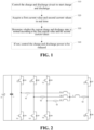
- an embodiment of the present application provides a method for controlling a charge and discharge circuit, where the charge and discharge circuit includes an M-phase motor winding, M being a positive integer.
- the method includes steps S10 to S40.
- the charge and discharge circuit is controlled to start charge and discharge.
- the charge and discharge circuit may include an M-phase motor winding, a current detection module, and M bridge arm groups of a motor inverter. M is a positive integer.
- the charge and discharge circuit may further include a capacitor connected in parallel with the battery. Each winding is connected to upper and lower bridge arm connection points of the corresponding bridge arm group.
- the current detection module includes a first current detection unit and at least M-1 second current detection units.
- the first current detection unit and the second current detection units may be current sensors.
- the neutral line of the M-phase motor winding, the first current detection unit and the upper and lower bridge arm connection points of the charge and discharge switching bridge arm group are connected in sequence; and the first current detection unit is configured to detect the first current value flowing through the neutral line.
- Each second current detection unit is connected in series between a corresponding winding and the corresponding bridge arm group to detect a second current value flowing through the corresponding winding.
- the motor inverter has M bridge arm groups, each bridge arm group includes an upper bridge arm and a lower bridge arm connected in series, and the upper and lower bridge arm connection points of each bridge arm group are connected to the corresponding winding in the M-phase motor winding.
- the charge and discharge circuit may further include at least one energy storage element connected in series between the first current detection unit and the neutral line of the M-phase motor winding.
- the energy storage element may be, for example, an inductor, a capacitor, or the like.
- the upper bridge arm and the lower bridge arm of the charge discharge switching bridge arm group are configured to be trigged by a charge-discharge enable signal to be turned on or off.
- the upper bridge arm includes a first switch, and the lower bridge arm includes a second switch; or, the upper bridge arm includes a first switch and a first diode connected in parallel, and the lower bridge arm includes a second switch and a second diode connected in parallel; and the negative electrode of the first diode is connected to the positive electrode of the power battery, the positive electrode of the first diode is connected to the negative electrode of the second diode, and the positive electrode of the second diode is connected to the negative electrode of the power battery.
- the power battery includes at least one battery pack.
- V1, V2, ... V8 serve as switches, and elements capable of functioning as switches, such as IGBT tubes, may be used; and D1, D2, ... D8 may all be diodes.
- the upper bridge arm of the charge and discharge switching bridge arm group includes V7 and D7 connected in parallel, and the lower bridge arm of the charge and discharge switching bridge arm group includes V8 and D8 connected in parallel.
- the upper bridge arm of the first bridge arm group includes V1 and D1 connected in parallel, and the lower bridge arm of the first bridge arm group includes V4 and D4 connected in parallel;
- the upper bridge arm of the second bridge arm group includes V2 and D2 connected in parallel, and the lower bridge arm of the second bridge arm group includes V5 and D5 connected in parallel;
- the upper bridge arm of the third bridge arm group includes V3 and D3 connected in parallel, and the lower bridge arm of the third bridge arm group includes V6 and D6 connected in parallel.
- the negative electrodes of D1, D2, D3 and D7 are all connected to the positive electrode of the power battery B1, and the positive electrodes of D4, D5, D6 and D8 are all connected to the negative electrode of the power battery B1.
- the current detection module includes a current sensor 1, a current sensor 2, a current sensor 3 and a current sensor 4. As shown in the figure, the charge and discharge circuit further includes a capacitor C1. An inductor L is further connected in series between the neutral point of the winding and the current sensor 4.
- the current flows in the following direction: positive electrode of power battery B1 ⁇ V1, V2 and V3 ⁇ current sensor 1, current sensor 2, current sensor 3 ⁇ winding LA, winding LB and winding LC ⁇ inductor L ⁇ current sensor 4 ⁇ V8 ⁇ negative electrode of power battery B1.
- V4, V5 and V6 are closed.
- a first current value and second current values are acquired in real time, where the first current value is a current value flowing through a neutral line of the M-phase motor winding, and the second current value is a current value flowing through a single winding.
- acquiring the first current value and the second current values in real time includes: receiving the first current value and the second current values detected in real time by the current detection module.
- the current value can be accurately and quickly obtained by detecting the current value flowing through the neutral line and the current values flowing through the windings by the current detection module.
- the current sensor 1, the current sensor 2, and the current sensor 3 detect a current value I1 of the winding LA, a current value I2 of the winding LB, and a current value I3 of the winding LC, respectively.
- the current sensor 4 detects a current value I4 flowing through the neutral line.
- the step S30 includes: if the absolute value of the difference between any two of the second current values is less than a first preset threshold, the absolute value of the difference between the sum of all the second current values and the first current value is less than a second preset threshold, the first current value is less than a third preset threshold, and each of the second current values is less than a fourth preset threshold, then determining the current charge and discharge state to be normal; otherwise, determining the current charge and discharge state to be abnormal.
- the current charge and discharge state is determined to be normal; otherwise, the current charge and discharge state is determined to be abnormal.
- the current charge and discharge state is normal according to the current value flowing through the neutral line of the M-phase motor winding and the current values flowing through the windings. If it is determined to be abnormal, the charge and discharge power is controlled to be reduced, thereby effectively reducing the safety hazards caused by abnormal current values and improving the safety of the charge and discharge circuit.
- acquiring the first current value and the second current values in real time includes:
- the current detection module includes a current sensor 5, a current sensor 6, and a current sensor 7.
- the current sensor 5 and the current sensor 6 detect the current value I5 of the winding LA and the current value I6 of the winding LB respectively.
- the current sensor 7 detects the current value I7 flowing through the neutral line, and the current value I8 flowing through the winding LC is equal to I7-I5-I6.
- the step S30 includes: if the absolute value of the difference between any two of the second current values is less than the first preset threshold, the first current value is less than the third preset threshold, and each of the second current values is less than the fourth preset threshold, then determining the current charge and discharge state to be normal; otherwise, determining it to be abnormal.
- the current charge and discharge state is determined to be normal; otherwise, it is determined to be abnormal;
- the current value of the difference between any two current values among the current values I5, I6 and I8 is less than the first preset threshold value, it means that the current values flowing through the three windings are substantially equal or the difference between the current values of any two windings is within the safe current difference range, where ensuring that the current values of the three windings remain substantially equal is one of the conditions to ensure the normal charge and discharge state;
- the current value I7 is less than the third preset threshold, I5 ⁇ the fourth preset threshold, I6 ⁇ the fourth preset threshold, and I8 ⁇ the fourth preset threshold, it means that the current value flowing through each winding and the current value flowing through the neutral line are both within the preset safe current value range, where ensuring that the current value flowing through each winding and the current value flowing through the neutral line are both within the preset safe current value range is one of the conditions to ensure the normal charge and discharge state; and when all the above conditions are met, the current charge and discharge state can be determined to be normal; otherwise, it means that the current charge and discharge
- controlling the charge and discharge power to be reduced includes: controlling the charge and discharge cycle to be shortened to reduce the charge and discharge power.
- a charge and discharge cycle is the sum of the charge time length and the discharge time length. Controlling the charge and discharge cycle to be shortened means controlling the charge time length and/or the discharge time length to be shortened, thereby controlling the entire charge and discharge cycle to be shortened.
- controlling the charge and discharge power to be reduced includes:
- controlling the charge and discharge power to be reduced according to the deviation degree includes:
- the correspondence between deviation degree and power reduction amplitude may be a mapping table, a function of the deviation degree and the power reduction amplitude, or the like. Through the correspondence between deviation degree and power reduction amplitude, the shortened time length of the charge and discharge cycle corresponding to any power reduction amplitude can be determined.
- the correspondence between charge and discharge power and charge and discharge cycle may be a mapping table, a function of the charge and discharge power and the charge and discharge cycle, or the like.
- Controlling the charge and discharge cycle to be shortened can be achieved by controlling the frequency of alternating formation of the charge loop and the discharge loop to be increased.
- the on-time of the charge loop is T1
- the on-time of the discharge loop is T2
- the charge and discharge cycle T T1+T2.
- Controlling the charge and discharge cycle T to be shortened can be achieved by shortening T1 and T2.
- the charge process and the discharge process are balanced. The electric energy stored in the windings and the energy storage element during the discharge process of the power battery is completely released and charged into the power battery during the charge process of the power battery.
- the on-off time of the switches V1-V8 can be regulated simultaneously, so that the on-time of the switches at a fixed frequency is reduced, thereby reducing the current of the inductor.
- the duty cycle of V1-V8 is reduced by a control signal.
- the specific value of the regulation can be regulated according to actual needs.
- the duty cycle is proportional to the current value.
- the inductor needs to be charged and discharged alternately to ensure that V1-V8 have the same duty cycle, or the duty cycles are regulated continuously so that the equivalent duty cycles of the four switches V1, V2, V3 and V8 and the four switches V4, V5, V6 and V7 are the same over a period of time, thereby achieving uniform charge and discharge.
- the current can be reduced by regulating the duty cycle, and the current can also be reduced by increasing the switching frequency of V1-V8.
- the higher the frequency the smaller the current value.
- the inductor needs to be charged and discharged alternately so that V1-V8 have the same frequency, or the frequencies are regulated continuously so that the equivalent frequencies of the four switching tubes V1, V2, V3 and V8 and the four switching tubes V4, V5, V6 and V7 are the same over a period of time, thereby achieving uniform charge and discharge.
- the four switches V1, V2, V3 and V8 need to be regulated simultaneously, and the four switches V4, V5, V6 and V7 need to be regulated simultaneously.
- the four switches V1, V2, V3, V8 and the four switches V4, V5, V6 and V7 can be regulated with different frequencies and duty cycles, as long as their equivalent frequency and duty cycle regulation ensures uniform charge and discharge of the inductor.
- the second current values are detected by the current detection module; and acquiring a deviation degree of the first current value and the second current values from a preset normal state includes:
- the deviation degree a(
- a, b, c, d, e, f, g and h are preset weights respectively.
- Ia, Ib, Ic, and Id are respectively the first preset threshold, the second preset threshold, the third preset threshold, and the fourth preset threshold.
- one of the second current values is calculated according to the first current value and other second current values detected by the current detection module; and acquiring a deviation degree of the first current value and the second current values from a preset normal state includes:
- the deviation degree a(
- a, b, c, e, f, g and h are preset weights respectively.
- Ia, Ic and Id are the first preset threshold, the third preset threshold and the fourth preset threshold respectively.
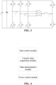
- FIG. 4 another embodiment of the present application provides an apparatus for controlling a charge and discharge circuit, where the charge and discharge circuit includes an M-phase motor winding, M being a positive integer.
- the method includes:
- the apparatus for controlling a charge and discharge circuit of this embodiment it is determined whether the current charge and discharge state is normal according to the current value flowing through the neutral line of the M-phase motor winding and the current values flowing through the windings. If it is determined to be abnormal, the charge and discharge power is controlled to be reduced, thereby effectively reducing the safety hazards caused by abnormal current values and improving the safety of the charge and discharge circuit.
- the current value acquisition module is further specifically configured to: receive the first current value and the second current values detected in real time by the current detection module.
- the state determination module is further specifically configured to: if the absolute value of the difference between any two of the second current values is less than a first preset threshold, the absolute value of the difference between the sum of all the second current values and the first current value is less than a second preset threshold, the first current value is less than a third preset threshold, and each of the second current values is less than a fourth preset threshold, then determine the current charge and discharge state to be normal; otherwise, determine it to be abnormal.
- the current value acquisition module includes:
- the state determination module is further specifically configured to: if the absolute value of the difference between any two of the second current values is less than the first preset threshold, the first current value is less than the third preset threshold, and each of the second current values is less than the fourth preset threshold, then determine the current charge and discharge state to be normal; otherwise, determine it to be abnormal.
- controlling, by the power control module, the charge and discharge power to be reduced includes: controlling the charge and discharge cycle to be shortened to reduce the charge and discharge power.
- the power control module includes a submodule configured to control the charge and discharge power to be reduced.
- the submodule includes:
- the second current values are each detected by the current detection module.
- the acquisition unit includes:
- one of the second current values is calculated according to the first current value and other second current values detected by the current detection module.
- the acquisition unit includes:
- the charge and discharge power reduction unit includes:
- Another embodiment of the present application provides a system for controlling a charge and discharge circuit, including a control module and the charge and discharge circuit connected to each other, where the charge and discharge circuit includes an M-phase motor winding; and the control module is configured to perform the method for controlling the charge and discharge circuit of any of the above implementations.
- the control module may be, for example, a component such as a controller that can perform the method for controlling the charge and discharge circuit of any of the above implementations.
- the system for controlling of this embodiment is based on the same inventive concept as the method for controlling provided in the embodiments of the present application and has the same beneficial effects as the method it adopts, operates or implements.
- Another embodiment of the present application provides an electronic device, characterized in that it includes a memory, a processor, and a computer program that is stored in the memory and is runnable on the processor, and the processor executes the program to implement the method for controlling a charge and discharge circuit of any of the above implementations.
- the electronic device 10 may include: a processor 100, a memory 101, a bus 102 and a communication interface 103.
- the processor 100, the communication interface 103 and the memory 101 are connected through the bus 102.
- the memory 101 has a computer program stored therein that can run on the processor 100, and when the processor 100 runs the computer program, it performs the method provided in any of the implementations described above.
- the memory 101 may include a high-speed random access memory (RAM), and may also include a non-volatile memory, such as at least one disk memory.
- RAM random access memory
- non-volatile memory such as at least one disk memory.
- the communication connection between the system network element and at least one other network element can be realized through at least one communication interface 103 (which may be wired or wireless) by using the Internet, wide area network, local area network, metropolitan area network, and the like.
- the bus 102 may be an ISA bus, a PCI bus, an EISA bus, or the like.
- the bus may be classified into an address bus, a data bus, a control bus, or the like.
- the memory 101 is used to store a program, and the processor 100 executes the program after receiving the execution instruction.
- the method disclosed in any of the implementations of the aforementioned embodiments of the present application can be applied in the processor 100 or implemented by the processor 100.
- the processor 100 may be an integrated circuit chip having signal processing capabilities. During implementation, various steps of the above method can be completed by an integrated logic circuit of hardware in the processor 100 or by instructions in the form of a software.
- the processor 100 mentioned above may be a general-purpose processor, which may include a central processing unit (CPU), a network processor (NP), and the like; it may also be a digital signal processor (DSP), an application-specific integrated circuit (ASIC), a field-programmable gate array (FPGA) or other programmable logic devices, discrete gates or transistor logic devices, and discrete hardware components.
- DSP digital signal processor
- ASIC application-specific integrated circuit
- FPGA field-programmable gate array
- a general-purpose processor may be a microprocessor, or the processor may be any conventional processor or the like.
- the steps of the method disclosed in conjunction with the embodiments of the present application can be directly embodied as being executed by a hardware coding processor, or can be embodied as being executed by a combination of hardware and software modules in the coding processor.
- the software module may be located in a random access memory, a flash memory, a read-only memory, a programmable read-only memory, or an electrically erasable programmable memory, a register, or other mature storage media in the art.
- the storage medium is located in the memory 101, and the processor 100 reads the information from the memory 101 and completes the steps of the above method in conjunction with its hardware.
- the electronic device provided by embodiments of the present application is based on the same inventive concept as the method provided in the embodiments of the present application and has the same beneficial effects as the method it adopts, operates or implements.
- Another embodiment of the present application provides a computer-readable storage medium having a computer program stored thereon, where the program is executed by a processor to implement the method for controlling a charge and discharge circuit of any of the implementations described above.
- the computer-readable storage medium shown in the figure is a compact disc 20 having a computer program (i.e., a program product) stored therein.
- a computer program i.e., a program product
- the computer program When executed by a processor, it performs the method provided by any of the implementations described above.
- examples of the computer-readable storage medium may also include, but are not limited to, phase change memory (PRAM), a static random access memory (SRAM), a dynamic random access memory (DRAM), other types of random access memory (RAM), read-only memory (ROM), electrically erasable programmable read-only memory (EEPROM), flash memory or other optical or magnetic storage media, which shall not be enumerated here.
- PRAM phase change memory
- SRAM static random access memory
- DRAM dynamic random access memory
- RAM random access memory
- ROM read-only memory
- EEPROM electrically erasable programmable read-only memory
- flash memory or other optical or magnetic storage media, which shall not be enumerated here.
- the computer-readable storage medium provided by the embodiments of the present application described above is based on the same inventive concept as the method for controlling provided in the embodiments of the present application and has the same beneficial effects as the method that the application program stored therein adopts, operates or implements.
- module is not intended to be limited to a particular physical form. Depending on the specific application, a module may be embodied as hardware, firmware, software, and/or a combination thereof. Furthermore, different modules may share common components or even be embodied by the same components. There may or may not be clear boundaries between different modules.
Landscapes
- Engineering & Computer Science (AREA)
- Power Engineering (AREA)
- Manufacturing & Machinery (AREA)
- Chemical & Material Sciences (AREA)
- Chemical Kinetics & Catalysis (AREA)
- Electrochemistry (AREA)
- General Chemical & Material Sciences (AREA)
- Microelectronics & Electronic Packaging (AREA)
- Transportation (AREA)
- Mechanical Engineering (AREA)
- Charge And Discharge Circuits For Batteries Or The Like (AREA)
Applications Claiming Priority (2)
| Application Number | Priority Date | Filing Date | Title |
|---|---|---|---|
| CN202210429620.1A CN115378104B (zh) | 2022-04-22 | 2022-04-22 | 充放电电路的控制方法、装置、系统、设备及存储介质 |
| PCT/CN2023/079213 WO2023202229A1 (fr) | 2022-04-22 | 2023-03-02 | Procédé et appareil de commande de circuit de charge et de décharge, système, dispositif et support de stockage |
Publications (2)
| Publication Number | Publication Date |
|---|---|
| EP4498568A1 true EP4498568A1 (fr) | 2025-01-29 |
| EP4498568A4 EP4498568A4 (fr) | 2025-07-16 |
Family
ID=84060715
Family Applications (1)
| Application Number | Title | Priority Date | Filing Date |
|---|---|---|---|
| EP23790892.6A Pending EP4498568A4 (fr) | 2022-04-22 | 2023-03-02 | Procédé et appareil de commande de circuit de charge et de décharge, système, dispositif et support de stockage |
Country Status (4)
| Country | Link |
|---|---|
| US (1) | US20250023374A1 (fr) |
| EP (1) | EP4498568A4 (fr) |
| CN (1) | CN115378104B (fr) |
| WO (1) | WO2023202229A1 (fr) |
Families Citing this family (1)
| Publication number | Priority date | Publication date | Assignee | Title |
|---|---|---|---|---|
| CN115378104B (zh) * | 2022-04-22 | 2024-02-13 | 宁德时代新能源科技股份有限公司 | 充放电电路的控制方法、装置、系统、设备及存储介质 |
Family Cites Families (17)
| Publication number | Priority date | Publication date | Assignee | Title |
|---|---|---|---|---|
| JP5460727B2 (ja) * | 2009-10-16 | 2014-04-02 | 三菱電機株式会社 | 車両用電源システム |
| JP6376997B2 (ja) * | 2015-03-13 | 2018-08-22 | シャープ株式会社 | 電力システムおよび電力システムの制御方法 |
| DE102018215901A1 (de) * | 2018-09-19 | 2020-03-19 | Robert Bosch Gmbh | Laderegler für eine Drehstromlichtmaschine |
| CN110971173B (zh) * | 2018-12-21 | 2021-01-19 | 比亚迪股份有限公司 | 动力电池的充电方法、电机控制电路及车辆 |
| CN111355435B (zh) * | 2018-12-21 | 2022-04-15 | 比亚迪股份有限公司 | 电机控制电路、车辆及其加热方法 |
| JP7370223B2 (ja) * | 2019-01-24 | 2023-10-27 | 株式会社Soken | 電力変換装置 |
| KR102814383B1 (ko) * | 2019-05-20 | 2025-05-29 | 현대자동차주식회사 | 모터 구동 시스템을 이용한 충전 전력 공급 시스템 |
| CN112440782B (zh) * | 2019-08-30 | 2022-06-14 | 比亚迪股份有限公司 | 电动汽车及其充电系统的控制方法、装置 |
| CN112550079B (zh) * | 2019-09-25 | 2022-09-06 | 比亚迪股份有限公司 | 能量转换装置及车辆 |
| KR102727990B1 (ko) * | 2020-04-14 | 2024-11-07 | 현대자동차주식회사 | 차량용 충전시스템 및 이의 배터리 충전 중지 방법 |
| CN113972707B (zh) * | 2020-07-23 | 2025-02-11 | 比亚迪股份有限公司 | 车辆、能量转换装置及其控制方法 |
| CN112034386B (zh) * | 2020-08-05 | 2023-10-10 | 苏州汇川联合动力系统股份有限公司 | 电机系统异常的识别方法、设备和计算机可读存储介质 |
| CN112260359B (zh) * | 2020-08-27 | 2024-01-09 | 江苏博强新能源科技股份有限公司 | 一种bms控制方法、系统、电子设备及存储介质 |
| CN114142112B (zh) * | 2020-09-04 | 2025-01-28 | 北京海博思创科技股份有限公司 | 电池系统的控制方法、装置、设备以及存储介质 |
| CN112793468A (zh) * | 2020-12-31 | 2021-05-14 | 江铃汽车股份有限公司 | 一种电池充放电保护方法、系统、存储介质及设备 |
| CN113517730B (zh) * | 2021-04-12 | 2024-04-09 | 华为数字能源技术有限公司 | 一种电池充放电系统、电路及方法 |
| CN115378104B (zh) * | 2022-04-22 | 2024-02-13 | 宁德时代新能源科技股份有限公司 | 充放电电路的控制方法、装置、系统、设备及存储介质 |
-
2022
- 2022-04-22 CN CN202210429620.1A patent/CN115378104B/zh active Active
-
2023
- 2023-03-02 EP EP23790892.6A patent/EP4498568A4/fr active Pending
- 2023-03-02 WO PCT/CN2023/079213 patent/WO2023202229A1/fr not_active Ceased
-
2024
- 2024-09-27 US US18/898,706 patent/US20250023374A1/en active Pending
Also Published As
| Publication number | Publication date |
|---|---|
| US20250023374A1 (en) | 2025-01-16 |
| EP4498568A4 (fr) | 2025-07-16 |
| CN115378104A (zh) | 2022-11-22 |
| CN115378104B (zh) | 2024-02-13 |
| WO2023202229A1 (fr) | 2023-10-26 |
Similar Documents
| Publication | Publication Date | Title |
|---|---|---|
| EP4501694A1 (fr) | Procédé et appareil de commande de circuit de charge et de décharge, et dispositif, système et support d'enregistrement | |
| US10811886B2 (en) | Charge control apparatus capable of high speed cell balancing and energy saving and method thereof | |
| CN108808754B (zh) | 分布式电池、电池控制方法与电动汽车 | |
| JP6295858B2 (ja) | バッテリ管理装置 | |
| CN104698388B (zh) | 一种移动终端的电池老化检测方法及其装置 | |
| CN109466372B (zh) | 一种充电剩余时间计算方法、装置及存储介质 | |
| US20130021000A1 (en) | Charge and discharge control apparatus | |
| JP2016170034A (ja) | 電池残量予測装置及びバッテリパック | |
| EP4512657A1 (fr) | Procédé et appareil de chauffage pour batterie de traction, et dispositif électronique, système et support de stockage | |
| WO2023010894A1 (fr) | Circuit de charge et de décharge, système de charge et de décharge et procédé de commande de charge et de décharge | |
| US20250023374A1 (en) | Method, apparatus, system, device and storage medium for controlling charge and discharge circuit | |
| WO2023236623A1 (fr) | Procédé et appareil d'égalisation de tension de bloc-batterie, dispositif électronique et support de stockage | |
| JP7196868B2 (ja) | 電池システム | |
| CN115377557B (zh) | 电池自加热控制方法、设备及存储介质 | |
| JP2024026232A (ja) | 蓄電池制御装置および制御方法 | |
| CN116438698A (zh) | 电池加热系统、及其控制方法、装置和电子设备 | |
| CN115377553A (zh) | 一种动力电池自加热方法、系统、存储介质及电子设备 | |
| CN119013865A (zh) | 投切控制方法、装置、储能系统、设备、介质及产品 | |
| JP2015155858A (ja) | 電池異常判断装置 | |
| US20210184622A1 (en) | Over-temperature protection system and method for dc capacitor of inverter | |
| US20250083567A1 (en) | Battery heating control method and control device | |
| CN117420463B (zh) | 电池的化学容量更新方法、装置、电子设备及存储介质 | |
| CN116626526B (zh) | 电池健康状态的检测方法、装置、终端及存储介质 | |
| EP4507192A1 (fr) | Procédé et appareil de commande pour moteur électrique et dispositif électronique et support d'enregistrement | |
| CN115395118A (zh) | 电池包充电平衡控制方法、装置、电池管理系统及介质 |
Legal Events
| Date | Code | Title | Description |
|---|---|---|---|
| STAA | Information on the status of an ep patent application or granted ep patent |
Free format text: STATUS: THE INTERNATIONAL PUBLICATION HAS BEEN MADE |
|
| PUAI | Public reference made under article 153(3) epc to a published international application that has entered the european phase |
Free format text: ORIGINAL CODE: 0009012 |
|
| STAA | Information on the status of an ep patent application or granted ep patent |
Free format text: STATUS: REQUEST FOR EXAMINATION WAS MADE |
|
| 17P | Request for examination filed |
Effective date: 20241021 |
|
| AK | Designated contracting states |
Kind code of ref document: A1 Designated state(s): AL AT BE BG CH CY CZ DE DK EE ES FI FR GB GR HR HU IE IS IT LI LT LU LV MC ME MK MT NL NO PL PT RO RS SE SI SK SM TR |
|
| RAP1 | Party data changed (applicant data changed or rights of an application transferred) |
Owner name: CONTEMPORARY AMPEREX TECHNOLOGY(HONG KONG) LIMITED |
|
| A4 | Supplementary search report drawn up and despatched |
Effective date: 20250618 |
|
| RIC1 | Information provided on ipc code assigned before grant |
Ipc: H02J 7/06 20060101AFI20250612BHEP Ipc: H02J 7/00 20060101ALI20250612BHEP Ipc: H01M 10/44 20060101ALI20250612BHEP Ipc: H02P 29/032 20160101ALI20250612BHEP Ipc: B60L 53/24 20190101ALI20250612BHEP Ipc: H02J 7/14 20060101ALI20250612BHEP |
|
| DAV | Request for validation of the european patent (deleted) | ||
| DAX | Request for extension of the european patent (deleted) |