EP4501191A1 - Distributeur de savon avec mécanisme de verrouillage magnétique - Google Patents
Distributeur de savon avec mécanisme de verrouillage magnétique Download PDFInfo
- Publication number
- EP4501191A1 EP4501191A1 EP24190652.8A EP24190652A EP4501191A1 EP 4501191 A1 EP4501191 A1 EP 4501191A1 EP 24190652 A EP24190652 A EP 24190652A EP 4501191 A1 EP4501191 A1 EP 4501191A1
- Authority
- EP
- European Patent Office
- Prior art keywords
- shell
- base
- dispenser
- hooking means
- sleeve
- Prior art date
- Legal status (The legal status is an assumption and is not a legal conclusion. Google has not performed a legal analysis and makes no representation as to the accuracy of the status listed.)
- Withdrawn
Links
Images

Classifications
-
- A—HUMAN NECESSITIES
- A47—FURNITURE; DOMESTIC ARTICLES OR APPLIANCES; COFFEE MILLS; SPICE MILLS; SUCTION CLEANERS IN GENERAL
- A47K—SANITARY EQUIPMENT; ACCESSORIES THEREFOR, e.g. TOILET ACCESSORIES
- A47K5/00—Holders or dispensers for soap, toothpaste or the like
- A47K5/06—Dispensers for soap
- A47K5/12—Dispensers for soap for liquid or pasty soap
-
- A—HUMAN NECESSITIES
- A47—FURNITURE; DOMESTIC ARTICLES OR APPLIANCES; COFFEE MILLS; SPICE MILLS; SUCTION CLEANERS IN GENERAL
- A47K—SANITARY EQUIPMENT; ACCESSORIES THEREFOR, e.g. TOILET ACCESSORIES
- A47K10/00—Body-drying implements; Toilet paper; Holders therefor
- A47K10/24—Towel dispensers; Toilet paper dispensers
- A47K10/32—Dispensers for paper towels or toilet paper
- A47K2010/3233—Details of the housing, e.g. hinges, connection to the wall
-
- A—HUMAN NECESSITIES
- A47—FURNITURE; DOMESTIC ARTICLES OR APPLIANCES; COFFEE MILLS; SPICE MILLS; SUCTION CLEANERS IN GENERAL
- A47K—SANITARY EQUIPMENT; ACCESSORIES THEREFOR, e.g. TOILET ACCESSORIES
- A47K10/00—Body-drying implements; Toilet paper; Holders therefor
- A47K10/24—Towel dispensers; Toilet paper dispensers
- A47K10/32—Dispensers for paper towels or toilet paper
- A47K2010/3246—Locking mechanisms for the housing
-
- A—HUMAN NECESSITIES
- A47—FURNITURE; DOMESTIC ARTICLES OR APPLIANCES; COFFEE MILLS; SPICE MILLS; SUCTION CLEANERS IN GENERAL
- A47K—SANITARY EQUIPMENT; ACCESSORIES THEREFOR, e.g. TOILET ACCESSORIES
- A47K2201/00—Details of connections of bathroom accessories, e.g. fixing soap or towel holder to a wall
- A47K2201/02—Connections to a wall mounted support
-
- E—FIXED CONSTRUCTIONS
- E05—LOCKS; KEYS; WINDOW OR DOOR FITTINGS; SAFES
- E05B—LOCKS; ACCESSORIES THEREFOR; HANDCUFFS
- E05B73/00—Devices for locking portable objects against unauthorised removal; Miscellaneous locking devices
- E05B73/0017—Anti-theft devices, e.g. tags or monitors, fixed to articles, e.g. clothes, and to be removed at the check-out of shops
- E05B73/0047—Unlocking tools; Decouplers
- E05B73/0052—Unlocking tools; Decouplers of the magnetic type
Definitions
- the object of the present invention is a soap dispenser equipped with a magnetic locking mechanism.
- soap dispensers for hygiene in most of the public and non-public toilets in the area are well known in the prior art. These dispensers comprise external shells whose purpose is to cover the internal soap dispensing mechanism, as well as to make the dispenser itself more aesthetically pleasing.
- the closing mechanism comprises a plate coupled to the inner surface of the casing, a latch that can be rotated about an axis of rotation and configured to engage the plate in a locked orientation.
- the locking mechanism also comprises a torsion spring, coupled with a magnet, to exert a force on the latch to keep it in the locked orientation.
- the magnet is configured to interact with a magnetic key to overcome the force of the torsion spring and bring the latch into the unlocked position.
- the object of the present invention is to provide a soap dispenser characterized by a locking mechanism on the outer shell that overcomes the drawbacks of the prior art.
- a further object of the above-mentioned invention is to present dispensers for dispensing liquid or powder soap characterized by an alternative outer shell locking mechanism to those presented in the prior art.
- a dispenser for dispensing liquid or powder soap in which the locking mechanism needs no lock, and consequently no tool to be inserted inside.
- the locking mechanism comprises easily accessible components that allow for quick and simplified opening and closing of the shell with respect to known locking mechanisms.
- a dispenser for dispensing liquid or powder soap in which the locking mechanism involves the use of a magnetic key or an element capable of generating a magnetic field; consequently, even if the predefined key is lost, it is possible to unlock the shell through the use of alternative elements.
- a dispenser for dispensing liquid or powder soap in which the locking mechanism allows the use of only components placed inside the shell, thereby not affecting the aesthetics of the dispenser.
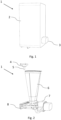
- the present invention relates to a dispenser 1, illustrated in Figure 1 , for dispensing soap characterized by a magnetic locking and unlocking mechanism.
- the dispenser 1 comprises a wall-fixable base 9 adapted to structurally support all the other elements of the dispenser 1 and a shell 2 which is movable with respect to the same base 9.
- the outer shell 2 internally, provides a locking mechanism of the shell 2 itself with respect to the wall-fixable base 9.
- this locking mechanism is positioned in the side portion of the upper inner side of the shell 2.
- this locking mechanism is most clearly observable from Figures 2 and 3a-b . It is characterized by first hooking means, fixed to the wall-fixable base 9 and second hooking means, fixed to the shell 2.
- the second hooking means comprise at least one movable element that can be constrained to the first hooking means to engage the shell 2 to the base 9, and that can be released from the first hooking means, in the presence of a magnetic field, to release the shell 2 from the base 9.
- the first fixing means comprise a ring 10, preferably with a circular geometry, as shown in Figure 3 , while the second ones comprise the presence of a sleeve 4 and at least one movable element, represented by a pin 5.
- This movable pin 5 can assume two different positions: the first position, in the locking step, and the second, in the unlocking step.
- the locking mechanism has a single movable pin 5, but the possibility of integrating further movable elements to provide, for example, greater stability and security during the locking step is not limited.
- the sleeve 4 has a passage channel into which the at least partially movable pin 5 is inserted, having the possibility to translate along the entire channel.
- the first position, during the locking step, is guaranteed by inserting at least one movable pin 5 into the ring 10, thus engaging the shell 2 outside the base. If there is any need to open the shell 2, for example, to refill the funnel-shaped container 6, to replace a defective element or simply for a periodic check, the pin is simply moved out of the ring 10 in which it is inserted, thus unlocking the shell 2 from the base.
- the sleeve 4, the at least one movable pin 5 and the ring 10 are arranged along the same longitudinal axis, and oriented in space in such a way that the sleeve 4, and consequently also the movable pin 5, is positioned above the ring 10 (arrangement shown in Figure 3a ). Thanks to this arrangement, due to the effect of gravity, the at least one movable pin 5 translates within the passage channel of the sleeve 4 until it engages in the ring 10 to hook the shell 2 to the base, thus defining the locking step.
- the unlocking step takes place by disengaging at least one movable pin 5 from the same ring 10.
- the wall-fixable base 9 is determined by an almost "L"-shape, characterized by two substantially orthogonal portions constrained by a joining edge.
- the vertical portion is the part comprising the through holes for wall mounting. Through these holes, it is possible to fix the base 9 to the wall using specific screws and dowels, while the horizontal portion remains suspended in a cantilever fashion and allows the various soap dispensing components to be supported.
- the shell 2 is free to make the opening movement, as shown in Figure 3b .
- the lower edge of the shell 2 is constrained to the joining edge of the two areas of the base 9 by at least one hinge mechanism 11 acting as a fulcrum, which allows the shell 2 to make a rotational movement along the sagittal plane of the dispenser 1.
- Figure 4 shows the unlocking step, in which the shell 2 is unhooked from the base and can perform a rotation, being pivotally constrained to the base.
- an element adapted to generate a magnetic field with a force of attraction such as to allow the movable pin 5 to move up along the channel of the sleeve 4, and thus unhook the shell 2 from the base 9.
- This element is represented by a portable magnetic key, provided together with the dispenser 1, configured to generate the magnetic field required to drive the at least one movable pin 5 up the sleeve 4.
- the above-mentioned shell 2 is made of plastic material to provide remarkable lightness and good impact resistance.
- it is determined by a parallelepiped shape with an internal cavity such that all the necessary components for the liquid or powder soap dispensing system can be accommodated, as in the examples in the accompanying figures.
- the shell 2 in its closed configuration where it is hooked to the base 9, completely covers the dispensing system on all faces, except for the lower face where the soap powder comes out.
- the lower face is preferably partially covered.
- the rear face is also not closed as there is an interface with the base 9 for wall mounting.
- the shell 2 allows protection of the device itself, the components inside it, as well as providing a more customisable aesthetic feature than the dispenser 1 in the absence of the shell 2.
- the shell 2 inside the cavity, covers a liquid or powder soap dispensing system.
- the various components of the soap dispensing system preferably include a support platform 8, shown in Figure 2 , which takes the same shape as the horizontal portion of the wall-fixable base 9, on which it rests.
- This orthogonal portion preferably has a channel, aligned with a corresponding passage in the shell 2 when the latter is hooked to the base 9, to allow the soap to flow out onto the user's hand.
- the dispensing system comprises a container 6 for refilling and storing the soap, visible in Figures 2 , 3a-b and 4 .
- a container 6 in the preferred embodiment of the invention, has a funnel shape and is particularly suitable for containing soap powder.
- the soap dispensing system comprises a dispensing mechanism 7, which, in the preferred embodiment of the invention, has a button to be pressed by a user for dispensing soap powder.
- the present invention allows for a more uniform and continuous shell 2, i.e. without a special hole for inserting the key for opening the lock, as is the case in the prior art. It should be noted that if the dispenser 1 is configured to dispense soap powder, a hole at the top of the shell 2 for inserting a key would be critical as it could allow water droplets to pass through and reach the inside of the dispensing mechanism, making the powder to be dispensed during use form a paste, thus compromising operation and optimal dispensing.
- the present invention also relates to a soap dispensing kit, comprising a dispenser 1 according to the invention and an unlocking key approachable to the shell 2 adapted to generate a magnetic field which, in correspondence of the closing mechanism, brings the at least one movable element from the first to the second position, according to the above description.
- the unlocking key comprises a magnetic body, such as a magnet.
Landscapes
- Health & Medical Sciences (AREA)
- Public Health (AREA)
- Containers And Packaging Bodies Having A Special Means To Remove Contents (AREA)
Applications Claiming Priority (1)
| Application Number | Priority Date | Filing Date | Title |
|---|---|---|---|
| IT102023000016659A IT202300016659A1 (it) | 2023-08-03 | 2023-08-03 | Dispenser per erogazione di sapone con meccanismo di blocco magnetico |
Publications (1)
| Publication Number | Publication Date |
|---|---|
| EP4501191A1 true EP4501191A1 (fr) | 2025-02-05 |
Family
ID=88291104
Family Applications (1)
| Application Number | Title | Priority Date | Filing Date |
|---|---|---|---|
| EP24190652.8A Withdrawn EP4501191A1 (fr) | 2023-08-03 | 2024-07-24 | Distributeur de savon avec mécanisme de verrouillage magnétique |
Country Status (2)
| Country | Link |
|---|---|
| EP (1) | EP4501191A1 (fr) |
| IT (1) | IT202300016659A1 (fr) |
Citations (2)
| Publication number | Priority date | Publication date | Assignee | Title |
|---|---|---|---|---|
| US20220018159A1 (en) * | 2018-12-04 | 2022-01-20 | Kimberly-Clark Worldwide, Inc. | Dispenser latching system |
| WO2023107635A1 (fr) | 2021-12-08 | 2023-06-15 | Bradley Corporation | Système de verrouillage magnétique |
Family Cites Families (1)
| Publication number | Priority date | Publication date | Assignee | Title |
|---|---|---|---|---|
| JPH05340145A (ja) * | 1992-06-08 | 1993-12-21 | Kitagawa Ind Co Ltd | 開き戸のロック機構 |
-
2023
- 2023-08-03 IT IT102023000016659A patent/IT202300016659A1/it unknown
-
2024
- 2024-07-24 EP EP24190652.8A patent/EP4501191A1/fr not_active Withdrawn
Patent Citations (2)
| Publication number | Priority date | Publication date | Assignee | Title |
|---|---|---|---|---|
| US20220018159A1 (en) * | 2018-12-04 | 2022-01-20 | Kimberly-Clark Worldwide, Inc. | Dispenser latching system |
| WO2023107635A1 (fr) | 2021-12-08 | 2023-06-15 | Bradley Corporation | Système de verrouillage magnétique |
Also Published As
| Publication number | Publication date |
|---|---|
| IT202300016659A1 (it) | 2025-02-03 |
Similar Documents
| Publication | Publication Date | Title |
|---|---|---|
| EP2277423B1 (fr) | Boîtier de distributeur doté d'un mécanisme de verrouillage | |
| JPS6238130A (ja) | 袋形液体分与器用の据付け用具 | |
| EP1702547B1 (fr) | Distributeur de fluides avec dispositif de verrouillage annulable | |
| JP2014034422A (ja) | 携帯用飲料容器の蓋体開閉機構 | |
| JP2013087451A (ja) | 回動式扉非常解錠システム | |
| EP4501191A1 (fr) | Distributeur de savon avec mécanisme de verrouillage magnétique | |
| CN108552898B (zh) | 一种隐藏式杯盖以及含有该杯盖的杯子 | |
| KR100981646B1 (ko) | 사물함 잠금장치 | |
| KR101689788B1 (ko) | 선반이 구비된 공중 화장실의 잠금장치 | |
| JP2000002030A (ja) | ロッカの施解錠装置 | |
| JP2002172244A (ja) | 遊技機裏側施錠装置 | |
| KR200400430Y1 (ko) | 수압 조절과 잠금 기능 갖춘 맨홀 뚜껑 | |
| JP3646796B2 (ja) | 表示錠 | |
| US12577810B2 (en) | Dispenser locking assemblies | |
| JP2610788B2 (ja) | カップホルダ | |
| KR200182205Y1 (ko) | 문용 로크핸들의 걸음쇠장치 | |
| KR102498612B1 (ko) | 용기의 캡 개폐장치 | |
| KR200325757Y1 (ko) | 자동잠금식 레버형 도어록 | |
| JP2003232159A (ja) | 扉装置 | |
| JP2003239574A (ja) | 平面ハンドル | |
| JPH0419181Y2 (fr) | ||
| JPH0637188Y2 (ja) | 鞄用施錠装置 | |
| JP2649099B2 (ja) | 扉の錠装置 | |
| JPS5920857Y2 (ja) | 計量米びつ | |
| KR200152268Y1 (ko) | 자물쇠 겸용 손잡이 |
Legal Events
| Date | Code | Title | Description |
|---|---|---|---|
| PUAI | Public reference made under article 153(3) epc to a published international application that has entered the european phase |
Free format text: ORIGINAL CODE: 0009012 |
|
| STAA | Information on the status of an ep patent application or granted ep patent |
Free format text: STATUS: THE APPLICATION HAS BEEN PUBLISHED |
|
| AK | Designated contracting states |
Kind code of ref document: A1 Designated state(s): AL AT BE BG CH CY CZ DE DK EE ES FI FR GB GR HR HU IE IS IT LI LT LU LV MC ME MK MT NL NO PL PT RO RS SE SI SK SM TR |
|
| STAA | Information on the status of an ep patent application or granted ep patent |
Free format text: STATUS: THE APPLICATION IS DEEMED TO BE WITHDRAWN |
|
| 18D | Application deemed to be withdrawn |
Effective date: 20250806 |