EP4501831A1 - Knotervorrichtung - Google Patents
Knotervorrichtung Download PDFInfo
- Publication number
- EP4501831A1 EP4501831A1 EP23779071.2A EP23779071A EP4501831A1 EP 4501831 A1 EP4501831 A1 EP 4501831A1 EP 23779071 A EP23779071 A EP 23779071A EP 4501831 A1 EP4501831 A1 EP 4501831A1
- Authority
- EP
- European Patent Office
- Prior art keywords
- yarn
- old
- hook
- stitch
- guide
- Prior art date
- Legal status (The legal status is an assumption and is not a legal conclusion. Google has not performed a legal analysis and makes no representation as to the accuracy of the status listed.)
- Pending
Links
Images


Classifications
-
- B—PERFORMING OPERATIONS; TRANSPORTING
- B65—CONVEYING; PACKING; STORING; HANDLING THIN OR FILAMENTARY MATERIAL
- B65H—HANDLING THIN OR FILAMENTARY MATERIAL, e.g. SHEETS, WEBS, CABLES
- B65H69/00—Methods of, or devices for, interconnecting successive lengths of material; Knot-tying devices ;Control of the correct working of the interconnecting device
- B65H69/04—Methods of, or devices for, interconnecting successive lengths of material; Knot-tying devices ;Control of the correct working of the interconnecting device by knotting
-
- D—TEXTILES; PAPER
- D01—NATURAL OR MAN-MADE THREADS OR FIBRES; SPINNING
- D01H—SPINNING OR TWISTING
- D01H15/00—Piecing arrangements ; Automatic end-finding, e.g. by suction and reverse package rotation; Devices for temporarily storing yarn during piecing
-
- B—PERFORMING OPERATIONS; TRANSPORTING
- B65—CONVEYING; PACKING; STORING; HANDLING THIN OR FILAMENTARY MATERIAL
- B65H—HANDLING THIN OR FILAMENTARY MATERIAL, e.g. SHEETS, WEBS, CABLES
- B65H2701/00—Handled material; Storage means
- B65H2701/30—Handled filamentary material
- B65H2701/31—Textiles threads or artificial strands of filaments
Definitions
- the present invention relates to a technique for a knotter device including a yarn selecting unit and a yarn joining unit.
- Patent Literature 1 discloses a yarn knotting device configured to tie a terminating end resultant of cutting a first yarn for which an operation has been completed, and a starting end of a second yarn for the next operation.
- the yarn knotting device mentioned above forms a stitch by rotating a knitting needle, with the action of the latch, without using a yarn guide in the process of forming a stitch with respect to a twisted stitch, and therefore, there has been a problem in terms of stability in forming the stitch.
- Patent Literature 1 JP 2002-35460 A
- the present invention has been made in view of the circumstance described above, and an object of the present invention is to provide a knotter device capable of tying a sheet bend knot stably.
- a knotter device is a knotter device including a yarn selecting unit and a yarn joining unit, in which the yarn selecting unit includes a guide lever configured to guide a new yarn fed from a yarn source to the yarn joining unit, and the yarn joining unit includes: a guide configured to guide an old yarn in a direction different from a direction in which the old yarn stretches; a knitting needle configured to hook and to twist the old yarn to form a twisted stitch, to hook another part of the old yarn guided by the guide, to form a stitch by passing the other part through the twisted stitch to one side, and to pass the new yarn guided by the guide lever through the stitch; a hook around which the old yarn is wound when the knitting needle forms the stitch and that is operable to unwind the old yarn; and a tension applying unit configured to increase tension of the old yarn so as to pass the stitch having the new yarn passed therethrough to another side.
- the sheet bend knot can be tied stably.
- a relative timing of unwinding the old yarn around the hook and increasing the tension of the old yarn by the tension applying section can be set to any timing.
- the hook may be enabled to change the timing for unwinding the old yarn.
- the hook includes a pair of hook-shaped members on which the old yarn is placeable, and the knitting needle is enabled to advance into and to retract from a space between the pair of hook-shaped members, and is enabled to be rotated about an axis.
- the guide is configured to guide a downstream part of the old yarn, the downstream part being downstream of the hook, to a position facing the knitting needle across the hook.
- the process for forming a stitch following a twisted stitch can be performed more stably.
- the knotter device further includes: a holder configured to hold the old yarn at a position upstream of the stitch, after the new yarn is passed through the stitch; and a cutter configured to cut an unnecessary part of the new yarn and the old yarn while the old yarn is being held by the holder, and the tension applying unit is configured to increase a tension of the old yarn after the old yarn is cut by the cutter.
- the tension applying unit includes the guide.
- the sheet bend knot can be tied stably.
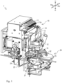
- the knotter device 1 is configured to tie a yarn 2 currently being used in a knitting machine, with a new yarn 2 wound on a yarn cone that is a yarn source, into a sheet bend knot.
- the knotter device 1 is disposed between the yarn source and the knitting machine. More specifically, the yarn source is disposed above the knotter device 1, and the knitting machine is disposed below the knotter device 1.
- the yarn 2 is fed downwards to the knotter device 1 from above.
- upstream in the direction in which the yarn is fed
- downstream in the direction in which the yarn is fed will be referred to as "downstream”.
- the knotter device 1 includes a yarn selecting unit 10, a yarn joining unit 20, and a controller 30.
- the yarn selecting plates 11 are enabled to select one yarn 2 from a plurality of yarns 2 fed from the yarn source.
- the yarn selecting plate 11 can select two or more yarns 2 from the plurality of yarns 2 fed from the yarn sources at the same time.
- the yarn 2 selected by the yarn selecting plate 11 will be referred to as "new yarn 2a”.
- the yarn 2 currently being used in the knitting machine will be referred to as "old yarn 2b”, and the yarn 2 other than the old yarn 2b and the new yarn 2a will be referred to as a "standby yarn 2c”.
- the yarn selecting plate 11 is disposed in plurality, with their plate surfaces facing in the left-right directions.
- the plurality of yarn selecting plates 11 are disposed side by side in the left-right direction.
- the yarn selecting plate 11 is provided rockably in the front-back direction, by solenoids that are provided respectively.
- the yarn 2 is inserted into a ring 11a provided at a distal end of the yarn selecting plate 11.
- the yarn holder 12 is provided downstream of the yarn selecting plate 11.
- the yarn holder 12 is displaceable between a holding position for holding the yarn 2, and a retracted position not holding the yarn 2.
- the yarn holder 12 is configured displaceable by air pressure, for example.
- the yarn holder 12 at the holding position can hold proximity of the tip ends of the plurality of respective yarns 2 at the same time. More specifically, the yarn holder 12 can hold a plurality of yarns 2 at the same time, but not the old yarn 2b.
- the separator 13 is disposed between the yarn selecting plates 11 and the yarn holder 12 in the yarn-feeding direction.
- the separator 13 has a plate-like shape, with its plate surfaces facing the front-rear directions.
- the separator 13 is capable of separating the old yarn 2b from the standby yarn 2c. Specifically, the old yarn 2b is guided behind the separator 13, downwards.
- the standby yarn 2 is passed through the ring 11a provided on the distal end of the yarn selecting plate 11, passed in front of the separator 13, and is held by the yarn holder 12.
- the yarn guide lever 14 is enabled to guide the new yarn 2a selected by the yarn selecting plate 11, into the yarn joining unit 20.
- the yarn guide lever 14 is disposed rotatably about an axis extending in the front-back direction.
- the yarn guide lever 14 is driven by a motor, for example.
- the yarn guide lever 14 can catch the new yarn 2a, on its distal end 14a, while swinging.
- a side surface projection 14b is disposed in the middle of the yarn guide lever 14.
- the yarn guide lever 14 can catch the old yarn 2b, on the side surface projection 14b, while swinging.
- the first yarn pressor 15 is disposed upstream of the yarn holder 12, on the front side of the separator 13.
- the first yarn pressor 15 is displaceable between a pressing position for pressing the yarn 2 so as not to move, and a retracted position not pressing the yarn 2.
- the first yarn pressor 15 is configured displaceable by air pressure, for example.
- the first yarn pressor 15 at the pressing position can press proximity of the tip ends of the yarns other than the new yarn 2a, that is, the old yarn 2b and the standby yarn 2c.
- the suction 16 is disposed downstream of the yarn holder 12.
- the suction 16 is enabled to suction and to hold the tip end of the yarn 2.
- the suction 16 is also enabled to remove the yarn waste generated in the yarn joining process, by suctioning.
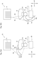
- the selected yarn selecting plate 11 When one yarn selecting plate 11 is selected by the yarn selecting unit 10 having the configuration described above, the selected yarn selecting plate 11 is swung and pulls the new yarn 2a, which is the yarn 2 passed through the ring 11a of the yarn selecting plate 11, rearwards, as shown in Fig. 2(b) . From this positioning, the yarn guide lever 14 is swung in the counterclockwise direction in front view, and the new yarn 2a having been pulled rearwards becomes hooked onto the distal end of the yarn guide lever 14, and the old yarn 2b becomes hooked onto the side surface projection 14b, as shown in Fig. 3(a) .
- the yarn selecting unit 10 can select one new yarn 2a from a plurality of yarns 2 fed from the yarn source, and guide the selected new yarn 2a to the yarn joining unit 20.
- the yarn joining unit 20 shown in Figs. 1 , 4 to 6 , and the like ties the new yarn 2a selected by the yarn selecting unit 10 and the old yarn 2b, into a sheet bend knot.
- the yarn joining unit 20 is disposed downstream of the yarn selecting unit 10.
- the yarn joining unit 20 mainly includes a knitting needle 21, a hook 22, a yarn guide 23, a cutter 24, a second yarn pressor 25, a third yarn pressor 26, and a tensioner 27.
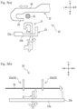
- the hook 22 shown in Figs. 1 , 4 , and 5 linearly supports the old yarn 2b.
- the hook 22 is disposed on the front side of the knitting needle 21.
- the hook 22 is provided movably in the left-right direction.
- the hook 22 includes a pair of hook-shaped members on which the old yarn 2b are placeable.
- an upper hook-shaped member will be referred to as an upper hook 22a
- a lower hook-shaped member will be referred to as a lower hook 22b.
- the upper hook 22a and the lower hook 22b are disposed with a space therebetween in the up-down direction.
- the upper hook 22a is disposed above the knitting needle 21.
- the lower hook 22b is disposed below the knitting needle 21.
- Each of the upper hook 22a and the lower hook 22b has a main body 28 and a hook portion 29.
- the longitudinal direction of the main body 28 is aligned in the left-right direction.
- the hook portion 29 is provided to a left end of the main body 28.
- the hook portion 29 has a hook-like shape bending rearwards and rightwards from the left end of the main body 28.
- the upper hook 22a and the lower hook 22b are enabled to hook the old yarn 2b onto their hook portions 29.
- the knitting needle 21 is enabled to advance into and to retract from the space between the upper hook 22a and the lower hook 22b, by moving back and forth.
- the yarn guide 23 shown in Figs. 1 , 4 , and 5 is capable of guiding the old yarn 2b in a direction different from the direction in which the old yarn 2b extends.
- the yarn guide 23 has a substantially L shape. More specifically, the yarn guide 23 includes a first portion 23a having its longitudinal direction aligned in a substantially up-down direction, and a second portion 23b extending rightwards from the bottom end of the first portion 23a. A top end of the first portion 23a is fixed to a gear 23A that is rotatable about an axis extending in the left-right direction. The first portion 23a is positioned on the left side of the knitting needle 21 and the hook 22. The second portion 23b is provided in a manner extending further rightwards than the old yarn 2b.
- the yarn guide 23 can apply tension to the old yarn 2b by swinging.
- the cutter 24 shown in Figs. 1 and 4 cuts unnecessary portions of the new yarn 2a and the old yarn 2b while the old yarn 2b is held by the second yarn pressor 25, which will to be described later.
- the cutter 24 is disposed upstream of the hook 22, and is enabled to cut a part of the new yarn 2a and the old yarn 2b, upstream of a knot between the new yarn 2a and the old yarn 2b.
- the cutter 24 is displaceable between a cutting position for cutting the new yarn 2a and the old yarn 2b, and a retracted position not enabled to cut the old yarn 2b and the new yarn 2a.
- the second yarn pressor 25 shown in Figs. 1 and 4 is configured to press the old yarn 2b.
- the second yarn pressor 25 is disposed downstream of the cutter 24.
- the second yarn pressor 25 is disposed upstream of the knitting needle 21 and the hook 22.
- the second yarn pressor 25 is displaceable between a pressing position for pressing the yarn 2 so as not to move, and a retracted position not pressing the yarn 2.
- the second yarn pressor 25 is configured displaceable by air pressure, for example.
- the second yarn pressor 25 at the pressing position can press a part of the old yarn 2b, on the upstream of the knot.
- Figs. 1 and 4 show the cutter 24 as being positioned at the cutting position, and the second yarn pressor 25 as being positioned at the retracted position; however, in practice, when the second yarn pressor 25 is at the pressing position, the cutter 24 is positioned at the cutting position.
- the third yarn pressor 26 shown in Figs. 1 and 4 is configured to press the old yarn 2b.
- the third yarn pressor 26 is disposed downstream of the second yarn pressor 25.
- the third yarn pressor 26 is disposed downstream of the knitting needle 21 and the hook 22.
- the third yarn pressor 26 is displaceable between a pressing position for pressing the yarn 2 so as not to move, and a retracted position not pressing the yarn 2.
- the third yarn pressor 26 is configured displaceable by air pressure, for example.
- the third yarn pressor 26 at the pressing position can press a part of the old yarn 2b, on the downstream side of the knot.
- the tensioner 27 applies tension to the old yarn 2b.
- the tensioner 27 is provided displaceable between a biasing position for applying tension to the old yarn 2b, with the biasing force of a spring, and a retracted position not applying tension to the old yarn 2b.
- the controller 30 shown in Fig. 6 is configured to control the operations of the yarn selecting unit 10 and the yarn joining unit 20.
- the controller 30 includes a storage unit such as a RAM, a ROM, and an HDD, and an arithmetic processing unit such as a CPU.
- the controller 30 can control the timing of the operations of the members included in the yarn selecting unit 10 and the yarn joining unit 20, as appropriate.
- the controller 30 can cause the members to move in cooperation with the knitting machine, and to join the yarns based on knitting data of the knitting machine, for example.
- step S1 shown in Fig. 7 the old yarn 2b is hooked onto the hook 22.
- the hook 22 is moved rightwards.
- the old yarn 2b is hooked onto the hook portions 29 of the hook 22.
- a twisted stitch 4 is formed with the old yarn 2b.
- a downstream part of the old yarn 2b being downstream of the hook 22, is dragged forwards.
- a bend of the old yarn 2b is formed in front of the knitting needle 21.
- the bent portion of the old yarn 2b will be referred to as a buffer 3.
- the buffer 3 extends from below the lower hook 22b toward the front side of the knitting needle 21, and then is bent downwards again toward the third yarn pressor 26.
- the hook 22 is then moved rightwards to pull the old yarn 2b further rightwards.
- the knitting needle 21 is then moved forwards, as shown in Fig. 9(c) , and goes into the space between the upper hook 22a and the lower hook 22b.
- the hook 22 is then moved leftwards, and the knitting needle 21 is moved back and retracted from the space between the upper hook 22a and the lower hook 22b, as shown in Fig. 10(a) , so that the old yarn 2b is hooked and dragged rearwards.
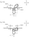
- the old yarn 2b is then twisted, as shown in Fig. 10(b) , by half-rotating the knitting needle 21, and a loop-shaped twisted stitch 4 is formed thereby.
- step S3 a stitch 5 is formed with the old yarn 2b.
- the knitting needle 21 is moved forwards, and the hook portion 21a hooks a part of the buffer 3 of the old yarn 2b.
- the knitting needle 21 is moved rearwards and retracted from the space between the upper hook 22a and the lower hook 22b, and the old yarn 2b is passed through the twisted stitch 4. In this manner, the stitch 5 is formed.
- the old yarn 2b is wound around the main body 28 of the lower hook 22b in the beginning.
- the old yarn 2b becomes wound around the hook portion 29 of the lower hook 22b, as shown in Fig. 11(b) .
- the yarn guide 23 is then swung in the direction opposite to the arrow shown in Fig. 5(b) , and goes back to the original position.
- the second yarn pressor 25 is then displaced to the pressing position, to press an upstream part of the old yarn 2b, being upstream of the hook 22.
- step S4 the new yarn 2a is pulled into the stitch 5. Specifically, after the knitting needle 21 is moved forwards, as shown in Fig. 12(a) , the yarn guide lever 14 of the yarn selecting unit 10 is swung as shown in Figs. 3(a) and 3(b) , so that the new yarn 2a is dragged to the front side of the hook 22. Next, as shown in Fig. 12(b) , the knitting needle 21 is moved rearwards, with the new yarn 2a hooked on the hook portion 21a, to pass the new yarn 2a through the stitch 5. The yarn guide lever 14 is then returned to the original position shown in Fig. 2(a) .
- step S5 the old yarn 2b wound around the hook 22 is then unwound. Specifically, as shown in Fig. 8(b) , by moving the hook 22 leftwards, the wound portion of the old yarn 2b is released from the lower hook 22b.
- step S6 tension is applied to the old yarn 2b and the new yarn 2a.
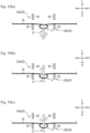
- the cutter 24 cuts a part of the new yarn 2a and the old yarn 2b above the hook 22, as shown in Fig. 13(a) , and the cutter having cut the yarns is displaced to the retracted position.
- the knitting needle 21 is then moved rearwards to pull the new yarn 2a hooked on the hook portion 21a rearwards, thereby pulling the cut end of the new yarn 2a toward the stitch 5.
- the knitting needle 21 is further moved rearwards, the cut end of the new yarn 2a is passed through the stitch 5 toward the rear side, and the new yarn 2a is released from the hook portion 21a of the knitting needle 21, as shown in Fig. 13(b) .
- the old yarn 2b is then pulled downstream by the tension of the tensioner 27, with an upstream part of the old yarn 2b, being upstream of the hook 22, is pressed down by the second yarn pressor 25.
- the stitch 5 and the new yarn 2a having passed through the stitch 5 are pulled out of the twisted stitch 4, toward the front side of the twisted stitch 4.
- the third yarn pressor 26 is then displaced to the pressing position to press a downstream part of the old yarn 2b, being downstream of the hook 22. Then, as the yarn guide 23 is rotated and hooks the old yarn 2b, as shown in Fig.
- the knotter device 1 it is possible to achieve a knot smaller than a reef knot by using a sheet bend knot to join the old yarn 2b and the new yarn 2a. Therefore, the knot resists less when the yarn is knitted using the knitting machine. Furthermore, unlike a splicer connecting the ends of the yarns by untwisting the fibers and splicing fibers, even in a case where the old yarn 2b and the new yarn 2a have different colors, it is possible to suppress smearing of the yarns at the knot.
- the new yarn 2a is a stretchable yarn such as an elastic yarn
- another pressing member is used to press a part of the new yarn 2a indicated by a two-dot chain line circle in Figs. 12(b) to 14(a) (e.g., a part near the stitch 5, and between the stitch 5 and the distal end 14a of the yarn guide lever 14) while the cutter 24 cuts the yarns by and the knitting needle 21 pulls the new yarn 2a.
- the new yarn 2a is cut with the cutter 24, the new yarn 2a, with the tension having applied thereto released, can be suppressed from coming off of the knot.
- the pressing force of the pressing member is released after the knot is tightened by the yarn guide 23.
- the members included in the yarn selecting unit 10 and the yarn joining unit 20 operate independently, without mechanically interoperating with one another. Therefore, the controller 30 can control the timing of the operations of the members of the yarn selecting unit 10 and the yarn joining unit 20 independently.
- the timing for releasing the old yarn 2b wound around the lower hook 22b may be delayed.
- the twisted stitch 4 can be kept large even while the stitch 5 having the new yarn 2a passed therethrough is being pulled out to the front side of the twisted stitch 4. Therefore, it is possible to pass the stitch 5 having the new yarn 2a passed therethrough easily through the twisted stitch 4.
- the stitch 5 having the new yarn 2a passed therethrough may be pulled too far toward the front side of the twisted stitch 4, and the twisted stitch 4 may become reversed and the new yarn 2a may become entangled with the old yarn 2b.
- the timing for releasing the old yarn 2b wound around the lower hook 22b may be advanced.
- the old yarn 2b wound around the lower hook 22b may be unwound between Figs. 12(a) and 12(b) , that is, before the new yarn 2a is pulled into the stitch 5. Because the size of the twisted stitch 4 is reduced, the stitch 5 having the new yarn 2a passed therethrough can be suppressed from being pulled too far behind the twisted stitch 4.
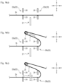
- the knitting needle 21 forms the twisted stitch 4 as a single stitch, but the twisted stitch 4 may be formed as multi-twisted stitch.
- a method of forming such a multi-twisted stitch 4 will now be described.
- the old yarn 2b is twisted by half-rotating the knitting needle 21, to form a looped twisted stitch 4.
- the knitting needle 21 is moved forwards within a range in which the latch does not come out of the twisted stitch 4, and goes into the space between the upper hook 22a and the lower hook 22b.
- the knitting needle 21 is half-rotated within the space between the upper hook 22a and the lower hook 22b.
- the knitting needle 21 is moved back.
- the knitting needle 21 is rotated in the same direction as before.
- the knitting needle 21 hooks the old yarn 2b on the hook portion 21a while being rotated.
- the old yarn 2b is wound twice around the knitting needle 21, as shown in Fig. 16(c) .
- the twisted stitch 4 may be tripled or more.
- the present invention is applicable to a knotter device including a yarn selecting unit and a yarn joining unit.
Landscapes
- Engineering & Computer Science (AREA)
- Mechanical Engineering (AREA)
- Textile Engineering (AREA)
- Knitting Machines (AREA)
Applications Claiming Priority (2)
| Application Number | Priority Date | Filing Date | Title |
|---|---|---|---|
| JP2022052496 | 2022-03-28 | ||
| PCT/JP2023/006520 WO2023189041A1 (ja) | 2022-03-28 | 2023-02-22 | ノッター装置 |
Publications (2)
| Publication Number | Publication Date |
|---|---|
| EP4501831A1 true EP4501831A1 (de) | 2025-02-05 |
| EP4501831A4 EP4501831A4 (de) | 2026-03-11 |
Family
ID=88200537
Family Applications (1)
| Application Number | Title | Priority Date | Filing Date |
|---|---|---|---|
| EP23779071.2A Pending EP4501831A4 (de) | 2022-03-28 | 2023-02-22 | Knotervorrichtung |
Country Status (5)
| Country | Link |
|---|---|
| EP (1) | EP4501831A4 (de) |
| JP (1) | JP7607828B2 (de) |
| KR (1) | KR20240165447A (de) |
| CN (1) | CN118922364A (de) |
| WO (1) | WO2023189041A1 (de) |
Family Cites Families (5)
| Publication number | Priority date | Publication date | Assignee | Title |
|---|---|---|---|---|
| CH305395A (de) * | 1951-06-25 | 1955-02-28 | Mellor Bromley & Co Limited | Vorrichtung zum Verknüpfen zweier Garnenden. |
| JPH081254Y2 (ja) * | 1991-11-14 | 1996-01-17 | ジューキ株式会社 | 機結び装置 |
| DE19504573C2 (de) * | 1995-02-11 | 2000-05-11 | Georg Diebel | Verfahren und Knotvorrichtung zum gleichzeitigen Verbindung der Fadenenden zweier Fadenscharen |
| JP2002035460A (ja) * | 2000-07-28 | 2002-02-05 | Brother Ind Ltd | 糸結び方法及びその装置 |
| JP4559337B2 (ja) * | 2005-10-13 | 2010-10-06 | 株式会社島精機製作所 | スプライサ装置 |
-
2023
- 2023-02-22 CN CN202380031320.0A patent/CN118922364A/zh active Pending
- 2023-02-22 JP JP2024511460A patent/JP7607828B2/ja active Active
- 2023-02-22 WO PCT/JP2023/006520 patent/WO2023189041A1/ja not_active Ceased
- 2023-02-22 EP EP23779071.2A patent/EP4501831A4/de active Pending
- 2023-02-22 KR KR1020247035688A patent/KR20240165447A/ko active Pending
Also Published As
| Publication number | Publication date |
|---|---|
| WO2023189041A1 (ja) | 2023-10-05 |
| JPWO2023189041A1 (de) | 2023-10-05 |
| CN118922364A (zh) | 2024-11-08 |
| JP7607828B2 (ja) | 2024-12-27 |
| EP4501831A4 (de) | 2026-03-11 |
| KR20240165447A (ko) | 2024-11-22 |
Similar Documents
| Publication | Publication Date | Title |
|---|---|---|
| KR101476951B1 (ko) | 솔기의 풀림 멈춤 방법, 솔기의 풀림 멈춤 장치 및 솔기 구조 | |
| JP4082930B2 (ja) | 糸撚り継ぎ装置 | |
| EP2345611B1 (de) | Garnwickelmaschine und Garnführungsverfahren | |
| RU2322536C2 (ru) | Способ предотвращения обрывания шва и устройство для его осуществления | |
| TWI523984B (zh) | The stray line of the stitch prevents the method and the stitching of the stitching device | |
| TWI766186B (zh) | 絲捲繞機 | |
| EP4501831A1 (de) | Knotervorrichtung | |
| CN102191632B (zh) | 线迹的绽线防止方法和线迹的绽线防止装置 | |
| JP4677454B2 (ja) | 糸のスプライシング方法及びその装置 | |
| JP6518619B2 (ja) | 編糸の解れ止め方法 | |
| JP2002035460A (ja) | 糸結び方法及びその装置 | |
| JP2005119881A (ja) | 繊維機械のためのボビンクリール | |
| JP4339001B2 (ja) | 織機における挟み付けたよこ糸の送り込みグリッパへの供給方法および供給装置 | |
| JP2002035461A (ja) | 糸結び装置 | |
| WO2010150582A1 (ja) | 種糸としての経糸の自動引込み装置、及び種糸としての経糸の自動引込み方法 | |
| CN217351686U (zh) | 自动穿线打结机 | |
| JP2002046942A (ja) | 糸結び装置 | |
| JP7309679B2 (ja) | ロープ結び装置 | |
| JP4265740B2 (ja) | 自動紐掛機用カッター台 | |
| CN103924391A (zh) | 线迹的绽线防止方法以及缝纫机 | |
| US4082328A (en) | Apparatus for joining undrawn yarns | |
| US3463528A (en) | Automatic knotter | |
| US2114685A (en) | Knotter | |
| JP4447049B6 (ja) | 種糸としての経糸の自動引込み装置、及び種糸としての経糸の自動引込み方法 | |
| GB276889A (en) | Method of and means for tying weavers knots |
Legal Events
| Date | Code | Title | Description |
|---|---|---|---|
| STAA | Information on the status of an ep patent application or granted ep patent |
Free format text: STATUS: THE INTERNATIONAL PUBLICATION HAS BEEN MADE |
|
| PUAI | Public reference made under article 153(3) epc to a published international application that has entered the european phase |
Free format text: ORIGINAL CODE: 0009012 |
|
| STAA | Information on the status of an ep patent application or granted ep patent |
Free format text: STATUS: REQUEST FOR EXAMINATION WAS MADE |
|
| 17P | Request for examination filed |
Effective date: 20240918 |
|
| AK | Designated contracting states |
Kind code of ref document: A1 Designated state(s): AL AT BE BG CH CY CZ DE DK EE ES FI FR GB GR HR HU IE IS IT LI LT LU LV MC ME MK MT NL NO PL PT RO RS SE SI SK SM TR |
|
| DAV | Request for validation of the european patent (deleted) | ||
| DAX | Request for extension of the european patent (deleted) | ||
| A4 | Supplementary search report drawn up and despatched |
Effective date: 20260209 |
|
| RIC1 | Information provided on ipc code assigned before grant |
Ipc: B65H 69/04 20060101AFI20260203BHEP Ipc: D01H 15/00 20060101ALI20260203BHEP |