EP4501839A2 - Grue et procédé de commande d'une telle grue - Google Patents
Grue et procédé de commande d'une telle grue Download PDFInfo
- Publication number
- EP4501839A2 EP4501839A2 EP24221600.0A EP24221600A EP4501839A2 EP 4501839 A2 EP4501839 A2 EP 4501839A2 EP 24221600 A EP24221600 A EP 24221600A EP 4501839 A2 EP4501839 A2 EP 4501839A2
- Authority
- EP
- European Patent Office
- Prior art keywords
- load
- crane
- acceleration
- pendulum
- control
- Prior art date
- Legal status (The legal status is an assumption and is not a legal conclusion. Google has not performed a legal analysis and makes no representation as to the accuracy of the status listed.)
- Pending
Links
Images


Classifications
-
- B—PERFORMING OPERATIONS; TRANSPORTING
- B66—HOISTING; LIFTING; HAULING
- B66C—CRANES; LOAD-ENGAGING ELEMENTS OR DEVICES FOR CRANES, CAPSTANS, WINCHES, OR TACKLES
- B66C13/00—Other constructional features or details
- B66C13/04—Auxiliary devices for controlling movements of suspended loads, or preventing cable slack
- B66C13/06—Auxiliary devices for controlling movements of suspended loads, or preventing cable slack for minimising or preventing longitudinal or transverse swinging of loads
- B66C13/063—Auxiliary devices for controlling movements of suspended loads, or preventing cable slack for minimising or preventing longitudinal or transverse swinging of loads electrical
-
- B—PERFORMING OPERATIONS; TRANSPORTING
- B66—HOISTING; LIFTING; HAULING
- B66C—CRANES; LOAD-ENGAGING ELEMENTS OR DEVICES FOR CRANES, CAPSTANS, WINCHES, OR TACKLES
- B66C23/00—Cranes comprising essentially a beam, boom, or triangular structure acting as a cantilever and mounted for translatory of swinging movements in vertical or horizontal planes or a combination of such movements, e.g. jib-cranes, derricks, tower cranes
- B66C23/02—Cranes comprising essentially a beam, boom, or triangular structure acting as a cantilever and mounted for translatory of swinging movements in vertical or horizontal planes or a combination of such movements, e.g. jib-cranes, derricks, tower cranes with non-adjustable and non-inclinable jibs mounted solely for slewing movements
- B66C23/022—Pivot axis common with column
-
- B—PERFORMING OPERATIONS; TRANSPORTING
- B66—HOISTING; LIFTING; HAULING
- B66C—CRANES; LOAD-ENGAGING ELEMENTS OR DEVICES FOR CRANES, CAPSTANS, WINCHES, OR TACKLES
- B66C2700/00—Cranes
- B66C2700/03—Cranes with arms or jibs; Multiple cranes
- B66C2700/0385—Cranes with trolleys movable along adjustable or slewable arms
-
- G—PHYSICS
- G05—CONTROLLING; REGULATING
- G05B—CONTROL OR REGULATING SYSTEMS IN GENERAL; FUNCTIONAL ELEMENTS OF SUCH SYSTEMS; MONITORING OR TESTING ARRANGEMENTS FOR SUCH SYSTEMS OR ELEMENTS
- G05B15/00—Systems controlled by a computer
- G05B15/02—Systems controlled by a computer electric
-
- G—PHYSICS
- G05—CONTROLLING; REGULATING
- G05B—CONTROL OR REGULATING SYSTEMS IN GENERAL; FUNCTIONAL ELEMENTS OF SUCH SYSTEMS; MONITORING OR TESTING ARRANGEMENTS FOR SUCH SYSTEMS OR ELEMENTS
- G05B2219/00—Program-control systems
- G05B2219/30—Nc systems
- G05B2219/40—Robotics, robotics mapping to robotics vision
- G05B2219/40043—Move object without swinging, no pendulum or swing motion at stop point
Definitions
- the present invention relates to a crane, in particular a tower crane, with a hoist rope that runs from a boom and carries a load-carrying device, drive devices for moving several crane elements and moving the load-carrying device, a control device for controlling the drive devices in such a way that the load-carrying device moves along a travel path, and a pendulum damping device for damping pendulum movements of the load-carrying device, wherein the said pendulum damping device has a pendulum sensor system for detecting pendulum movements of the hoist rope and/or the load-carrying device and a controller module with a closed control loop for influencing the control of the drive devices depending on pendulum signals that indicate pendulum movements detected by the pendulum sensor system and are fed back to the control loop.
- the invention also relates to a method for controlling a crane, in which the control of the drive devices is influenced by a pendulum damping device depending on pendulum-relevant parameters.
- some types of crane are inherently flexible and can swing themselves, which is difficult for the crane operator to predict given the various axes of movement.
- the slewing gear by means of which the tower with the boom provided on it or the boom are rotated relative to the tower about an upright axis of rotation, as well as the trolley drive, by means of which the trolley can be moved along the boom, and the hoist, by means of which the hoist rope can be adjusted and the load hook can be raised and lowered, must each be operated and controlled.
- the luffing drive for luffing the boom up and down and the telescoping drive for extending and retracting the telescopic sections are also operated, and possibly also a luffing jib drive if there is a luffing jib on the telescopic boom.
- other drive devices may also be controlled.
- the drive devices mentioned are usually operated and controlled by the crane operator using appropriate control elements, for example in the form of joysticks, toggle switches, rotary knobs and sliders and the like, which experience shows requires a lot of feeling and experience in order to reach the target points quickly and yet gently without major pendulum movements of the load hook. While the crane should travel as quickly as possible between the target points in order to achieve a high level of performance, it should stop gently at the respective target point without the load hook swinging with the load attached to it.
- Such sway damping devices for cranes are known in various designs, for example by controlling the slewing gear, luffing gear and trolley drives depending on certain sensor signals, for example inclination and/or gyroscope signals.
- sensor signals for example inclination and/or gyroscope signals.
- the rope angle relative to the vertical and its change in the form of the rope angular velocity are measured by means of a gyroscope unit in order to automatically intervene in the control if a limit value for the rope angular velocity relative to the vertical is exceeded.
- dynamic effects in the structural parts can lead to time delays in the transmission to the hoist rope and the load hook when drives are operated to dampen the pendulum.
- the dynamic effects mentioned can also have excessive or even counterproductive effects on a load pendulum. For example, if a load swings backwards towards the tower because the trolley drive is initially operated too quickly and the pendulum damping device counteracts this by slowing down the trolley drive, the boom can pitch because the tower deforms accordingly, which can impair the desired pendulum damping effect.
- tower cranes have the problem that, due to their lightweight construction, in contrast to certain other crane types, the vibrations of the steel structure cannot be ignored but should be treated in a closed loop control system for safety reasons, as otherwise dangerous unstable oscillation of the steel structure can usually occur.
- the basic aim is therefore to detect the pendulum movements and actively counteract them by means of a control system.
- a control system can serve as an assistance system that allows the crane operator to specify the load movement directly via the control devices (instead of the bridge or trolley movement).
- This support can increase occupational safety and productivity. Vibration damping is also an important prerequisite for the full automation of bridge cranes.
- the present invention is based on the object of creating an improved crane and an improved method for controlling it, which avoid the disadvantages of the prior art and develop the latter in an advantageous manner.
- the payload should be moved in accordance with the crane operator's setpoints and unwanted pendulum movements should be actively dampened via a control system, while at the same time unwanted movements of the structural dynamics should not be excited but also dampened by the control system in order to increase safety, make it easier to operate and automate.
- improved pendulum damping should be achieved in tower cranes, which better takes into account the various influences of the crane structure.
- Such an inertial measuring device attached to the load-carrying device which is sometimes also referred to as an IMU, can have acceleration and yaw rate sensor means for providing acceleration and yaw rate signals which, on the one hand, represent translational accelerations along various spatial axes and on the other hand, they include rotation rates or gyroscopic signals with respect to different spatial axes. Rotation rates can be rotational speeds, but in principle also rotational accelerations or both.
- the inertial measuring device can detect accelerations in three spatial axes and rotation rates about at least two spatial axes.
- the acceleration sensor means can be designed to operate in three axes and the gyroscope sensor means can be designed to operate in two axes.
- the inertial measuring device attached to the load hook can advantageously transmit its acceleration and rotation rate signals and/or signals derived therefrom wirelessly to a control and/or evaluation device that can be attached to a structural part of the crane or arranged separately near the crane.
- the transmission can be made to a receiver that can be attached to the trolley and/or to the suspension from which the hoist rope runs.
- the transmission can advantageously be made via a WLAN connection, for example.
- Such a wireless connection of an inertial measuring device makes it very easy to retrofit sway damping to existing cranes without the need for complex retrofitting measures. Essentially, all that needs to be done is to attach the inertial measuring device to the load hook and the receiver that communicates with it, which transmits the signals to the control or regulating device.
- the deflection of the load hook or the hoist rope relative to the vertical can be advantageously determined from the signals of the inertial measuring device in a two-stage process.
- the tilting of the load hook is determined, since this cannot be compared with the deflection of the load hook relative to the trolley or the suspension point and the deflection of the hoist rope relative to the vertical. must match, the required deflection of the load hook or the hoist rope relative to the vertical is then determined from the tilting of the load hook and its acceleration. Since the inertial measuring device is attached to the load hook, the acceleration and yaw rate signals are influenced by both the pendulum movements of the hoist rope and the dynamics of the load hook tilting relative to the hoist rope.
- a model-based control system calculates a stabilizing feedback of this pendulum angle estimate to the control signals of the bridge or tower crane.
- the highly accurate pendulum angle estimation that can be achieved in this way can generally be used for universal hook types (which can be susceptible to certain pendulum oscillations) and requires sensors that can be retrofitted very cost-effectively. At the same time, there are considerable advantages such as increased safety, improved operability, increased handling capacity and automation.
- the pendulum sensor system can be retrofitted cost-effectively.
- the tilting of the load hook is first determined from the signals of the inertial measuring device using a complementary filter which makes use of the different characteristics of the translational acceleration signals and the gyroscopic signals of the inertial measuring device, whereby alternatively or additionally a Kalman filter can also be used to determine the tilting of the load hook from the acceleration and yaw rate signals.
- the required deflection of the load hook relative to the trolley or relative to the suspension point of the hoist rope and/or the deflection of the hoist rope relative to the vertical can then be determined using a Kalman filter and/or by means of a static calculation from horizontal inertial acceleration and acceleration due to gravity.
- the pendulum sensor system can have first determination means for determining and/or estimating a tilting of the load-handling device from the acceleration and rotation rate signals of the inertial measuring device and second determination means for determining the deflection of the hoist cable and/or the load-handling device relative to the vertical from the determined tilting of the load-handling device and an inertial acceleration of the load-handling device.
- the first determination means mentioned can in particular have a complementary filter with a high-pass filter for the rotation rate signal of the inertial measuring device and a low-pass filter for the acceleration signal of the inertial measuring device or a signal derived therefrom, wherein the complementary filter mentioned can be designed to combine a rotation rate-based estimate of the tilting of the load-carrying device, which is based on the high-pass filtered rotation rate signal, and an acceleration-based estimate of the tilting of the load-carrying device, which is based on the low-pass filtered acceleration signal. and to determine the required tilt of the load handling device from the linked yaw rate and acceleration-based estimates of the tilt of the load handling device.
- the yaw rate-based estimation of the tilting of the load-handling device can include an integration of the high-pass filtered yaw rate signal.
- the second determination means for determining the deflection of the load hook or the hoist rope relative to the vertical on the basis of the determined tilting of the load hook can have a filter and/or observer device which takes into account the determined tilting of the load-handling device as an input variable and determines the deflection of the hoist rope and/or the load-handling device relative to the vertical from an inertial acceleration on the load-handling device.
- the said filter and/or observer device can in particular comprise a Kalman filter, in particular an extended Kalman filter.
- the second determination means can also comprise a calculation device for calculating the deflection of the hoist rope and/or the load-carrying means relative to the vertical from a static relationship of the accelerations, in particular from the quotient of a horizontal inertial acceleration and the acceleration due to gravity.
- the detection device for detecting the position of the load hook can advantageously also comprise an imaging sensor, for example a camera, which looks essentially vertically downwards from the suspension point of the hoist rope, for example the trolley.
- An image evaluation device can identify the crane hook in the image provided by the imaging sensor and determine its eccentricity or its displacement from the image center, which is a measure of the deflection of the crane hook relative to the vertical and thus characterizes the load swing.
- a gyroscopic sensor can detect the hoist rope pull-off angle from the boom and/or relative to the vertical and feed it to the Kalman filter.
- the sway damping measures can take into account not only the actual swaying movement of the rope itself, but also the dynamics of the crane structure or the steel construction of the crane and its drive trains.
- the crane is no longer assumed to be an immobile rigid body that converts the drive movements of the drive devices directly and identically, i.e. 1:1, into movements of the suspension point of the hoist rope.
- the sway damping device considers the crane as a soft structure that shows elasticity and flexibility in its steel construction or structural parts, such as the tower lattice and the boom, and in its drive trains when accelerating, and takes these dynamics of the structural parts of the crane into account when influencing the control of the drive devices to dampen the sway.
- both the pendulum dynamics and the structural dynamics are actively dampened by means of a closed control loop.
- the entire system dynamics are actively controlled as a coupling of the pendulum, drive and structural dynamics of the tower crane in order to move the payload in accordance with the target specifications.
- Sensors are used on the one hand to measure system variables of the pendulum dynamics and on the other hand to measure system variables of the structural dynamics, whereby non-measurable system variables are measured in a model-based observer. can be estimated as system states.
- the control signals for the drives are calculated by a model-based control system as state feedback of the system states, which closes a control loop and results in a changed system dynamic.
- the control system is designed in such a way that the system dynamics of the closed control loop are stable and control errors are quickly compensated.
- a closed control loop is advantageously provided on the crane, in particular a tower crane or bridge crane, with structural dynamics by feeding back measurements not only of the pendulum dynamics but also of the structural dynamics.
- the pendulum damping device also includes a structural dynamics sensor system for detecting dynamic deformations and movements of the crane structure or at least structural components thereof, wherein the controller module of the pendulum damping device, which influences the control of the drive device in a pendulum-damping manner, is designed to take into account both the pendulum movements detected by the pendulum sensor system and the dynamic deformations of the structural components of the crane detected by the structural dynamics sensor system when influencing the control of the drive devices. Both the pendulum sensor signals and the structural dynamics sensor signals are fed back to the closed control loop.
- the pendulum damping device does not consider the crane or machine structure as a rigid, infinitely stiff structure, so to speak, but assumes an elastically deformable and/or flexible and/or relatively soft structure which - in addition to the positioning axes of the machine such as the boom jib axis or the tower rotation axis - allows movements and/or position changes through deformations of the structural components.
- the vibration dynamics of the structural components are reduced by the control behavior of the control device.
- the vibration is actively dampened by the driving behavior or is not stimulated at all by the control behavior.
- the steel structure is also protected and subjected to less stress. Shock loads in particular are reduced by the control behavior.
- this method can be used to define the influence of driving behavior.
- the pitching oscillation in particular can be reduced and dampened. This means that the load behaves more smoothly and no longer sways up and down in the resting position.
- Transverse pendulum movements in the circumferential direction around the upright boom axis of rotation can also be better controlled by taking tower torsion and boom swivel bending deformations into account.
- the aforementioned elastic deformations and movements of the structural components and drive trains and the resulting inherent movements can basically be determined in different ways.
- the structural dynamics sensor technology provided for this purpose can be designed to detect elastic deformations and movements of structural components under dynamic loads.
- Such structural dynamics sensors can, for example, include deformation sensors such as strain gauges on the steel structure of the crane, for example the lattice structures of the tower and/or the boom.
- yaw rate sensors in particular in the form of gyroscopes, gyro sensors and/or gyrometers, and/or acceleration and/or speed sensors can be provided in order to detect certain movements of structural components such as pitching movements of the boom tip and/or rotational dynamic effects on the boom and/or torsional and/or bending movements of the tower.
- inclination sensors can be provided to detect inclinations of the boom and/or inclinations of the tower, in particular deflections of the boom from the horizontal and/or deflections of the tower from the vertical.
- the structural dynamics sensor technology can work with different types of sensors, in particular by combining different types of sensors with one another.
- Strain gauges and/or acceleration sensors and/or yaw rate sensors in particular in the form of gyroscopes, gyro sensors and/or gyrometers, can advantageously be used to detect the deformations and/or dynamic internal movements of structural components of the crane, with the acceleration sensors and/or yaw rate sensors preferably being designed to detect three axes.
- Such structural dynamics sensors can be provided on the boom and/or on the tower, in particular on its upper section on which the boom is mounted. to capture the dynamics of the tower. For example, jerky lifting movements lead to pitching movements of the boom, which are accompanied by bending movements of the tower, while a post-swing of the tower in turn leads to pitching oscillations of the boom, which are accompanied by corresponding load hook movements.
- an angle sensor can be provided to determine the differential angle of rotation between an upper tower end section and the boom, whereby, for example, an angle sensor can be attached to the upper tower end section and to the boom, the signals of which can indicate the differential angle of rotation when the difference is considered.
- a rotation rate sensor can advantageously also be provided to determine the rotation speed of the boom and/or the upper tower end section in order to be able to determine the influence of the tower torsion movement in conjunction with the aforementioned differential angle of rotation. This can be used to achieve a more precise load position estimate on the one hand, but also to actively dampen the tower torsion during operation on the other.
- two- or three-axis yaw rate sensors and/or acceleration sensors can be attached to the boom tip and/or to the boom in the area of the upright crane axis of rotation in order to be able to determine structural dynamic movements of the boom.
- motion and/or acceleration sensors can also be assigned to the drive trains in order to be able to record the dynamics of the drive trains.
- the pulleys of the trolley for the hoist rope and/or pulleys for a guy rope of a luffing jib can be assigned rotary encoders in order to be able to record the actual rope speed at the relevant point.
- suitable motion and/or speed and/or acceleration sensors are also assigned to the drive devices themselves in order to be able to record the drive movements of the drive devices accordingly and to relate them to the estimated and/or recorded deformations of the structural components or the steel construction and compliances in the drive trains.
- the motion and/or acceleration component of a structural part can be determined which is due to a dynamic deformation or twisting of the crane structure and in addition to the actual crane movement, as induced by the drive movement and would also occur with a completely stiff, rigid crane.
- the slewing gear of a tower crane is adjusted by 10°, but only a twist of 9° is detected at the boom tip, it can be concluded that there is torsion of the tower and/or bending deformation of the boom, which can in turn be compared at the same time with, for example, the twisting signal of a rotation rate sensor attached to the tower tip in order to be able to differentiate between tower torsion and boom bending. If the load hook is lifted by one meter from the hoist, but at the same time a downward pitching movement of, for example, 1° is detected on the boom, the actual load hook movement can be determined by taking into account the outreach of the trolley.
- the structural dynamics sensor system can detect different directions of movement of the structural deformations.
- the structural dynamics sensor system can have at least one radial dynamics sensor for detecting dynamic movements of the crane structure in an upright plane parallel to the crane boom, and at least one swivel dynamics sensor for detecting dynamic movements of the crane structure about an upright crane axis of rotation, in particular the tower axis.
- the controller module of the pendulum damping device can be designed to influence the control of the drive devices, in particular a trolley drive and slewing gear drive, depending on the detected dynamic movements of the crane structure in the upright, boom-parallel plane, in particular parallel to the boom longitudinal direction, and the detected dynamic movements of the crane structure about the upright crane axis of rotation.
- the structural dynamics sensor system can have at least one lifting dynamics sensor for detecting vertical dynamic deformations of the crane boom and the controller module of the pendulum damping device can be designed to influence the control of the drive devices, in particular a hoist drive, depending on the detected vertical dynamic deformations of the crane boom.
- the structural dynamics sensor system is advantageously designed to detect all eigenmodes of the dynamic twists of the crane boom and/or the crane tower whose eigenfrequencies are in a predetermined frequency range.
- the structural dynamics sensor system can have at least one, preferably several tower sensor(s), which is/are arranged at a distance from a node of a natural tower vibration, for detecting tower twists, and at least one, preferably several boom sensor(s), which is/are arranged at a distance from a node of a natural boom vibration, for detecting boom twists.
- sensors can be placed to record a structural movement in such a way that it is possible to observe all eigenmodes whose eigenfrequencies lie in the relevant frequency range.
- one sensor per pendulum movement direction is sufficient, but in practice the use of several sensors is recommended.
- placing a single sensor at a node of the measured variable of a structural eigenmode e.g. position of the trolley at a rotation node of the first cantilever eigenmode
- leads to a loss of observability which can be avoided by adding a sensor at another position.
- the use of three-axis yaw rate sensors or acceleration sensors at the boom tip and on the boom near the slewing gear is recommended.
- the structural dynamics sensor system can basically work with different sensor types to detect the eigenmodes, in particular by combining different sensor types with one another.
- the aforementioned strain gauges and/or acceleration sensors and/or yaw rate sensors in particular in the form of gyroscopes, gyro sensors and/or gyrometers, can advantageously be used to detect the deformations and/or dynamic internal movements of structural components of the crane, with the acceleration sensors and/or yaw rate sensors preferably being designed to detect three axes.
- the structural dynamics sensor system can have at least one rotation rate and/or acceleration sensor and/or strain gauge for detecting dynamic tower deformations and at least one rotation rate and/or acceleration sensor and/or strain gauge for detecting dynamic boom deformations.
- rotation rate and/or acceleration sensors can be provided on various tower sections, in particular at least on the tower tip and at the articulation point of the boom and possibly in a tower middle section below the boom.
- rotation rate and/or acceleration sensors can be provided on various sections of the boom, in particular at least on the boom tip and/or the trolley and/or the boom foot to which the boom is articulated, and/or on a boom section on the hoist.
- the sensors mentioned are arranged on the respective structural component in such a way that they can detect the eigenmodes of its elastic distortions.
- the pendulum damping device can also comprise an estimation device which estimates deformations and movements of the machine structure under dynamic loads that arise as a function of control commands entered at the control station and/or as a function of certain control actions of the drive devices and/or as a function of certain speed and/or acceleration profiles of the drive devices, taking into account the conditions that characterize the crane structure.
- an estimation device can be used to estimate system variables of the structural dynamics, and possibly also of the pendulum dynamics, which cannot be detected by sensors or can only be detected with difficulty.
- Such an estimation device can, for example, access a data model in which structural parameters of the crane such as tower height, boom length, stiffness, area moments of inertia and the like are stored and/or linked to one another in order to then estimate, based on a specific load situation, i.e. weight of the load carried by the load hook and current outreach, which dynamic effects, i.e. deformations in the steel structure and in the drive trains, result from a specific actuation of a drive device.
- the pendulum damping device can then intervene in the control of the drive devices and influence the control variables of the drive controllers of the drive devices in order to avoid or reduce pendulum movements of the load hook and the hoist rope.
- the determination device for determining such structural deformations can have a calculation unit that calculates these structural deformations and the resulting structural part movements using a stored calculation model depending on the control commands entered at the control station.
- a model can be constructed similarly to a finite element model or can be a finite element model, but advantageously a model that is significantly simplified compared to a finite element model is used, which can be determined empirically, for example, by recording structural deformations under certain control commands and/or load conditions on the real crane or the real machine.
- a calculation model can For example, you can work with tables in which certain deformations are assigned to certain control commands, whereby intermediate values of the control commands can be converted into corresponding deformations by means of an interpolation device.
- the controller module in the closed control loop can comprise a filter device or an observer which, on the one hand, observes the structural dynamic crane reactions and the hoist rope or load hook pendulum movements as they are detected by the structural dynamics sensors and the pendulum sensors and are set for certain control variables of the drive controller, so that the observer or filter device can influence the control variables of the controller based on the observed crane structure and pendulum reactions, taking into account predetermined laws of a dynamic model of the crane, which can fundamentally be of different nature and can be obtained by analyzing and simulating the steel structure.
- Such a filter or observer device can be designed in particular in the form of a so-called Kalman filter, to which the actuating variables of the drive controller of the crane are fed as input variables on the one hand and on the other hand both the pendulum signals of the pendulum sensors and the structural dynamics signals fed back to the control loop, which indicate deformations and/or dynamic internal movements of the structural components, and which, from these input variables, influences the actuating variables of the drive controllers accordingly using Kalman equations that model the dynamic system of the crane structure, in particular its steel components and drive trains, in order to achieve the desired pendulum-damping effect.
- Kalman filter to which the actuating variables of the drive controller of the crane are fed as input variables on the one hand and on the other hand both the pendulum signals of the pendulum sensors and the structural dynamics signals fed back to the control loop, which indicate deformations and/or dynamic internal movements of the structural components, and which, from these input variables, influences the actuating variables of the drive controllers accordingly using Kalman equations that model the dynamic
- a two-degree-of-freedom control structure is used for pendulum damping, through which the state feedback described above is supplemented by a feedforward control.
- the state feedback serves to ensure stability and to quickly compensate for control errors, while the feedforward control ensures good control behavior, which ideally means that no control errors occur at all.
- the feedforward control can advantageously be determined using the known method of differential flatness.
- the method of differential flatness mentioned above reference is made to the Dissertation "Application of flatness-based analysis and control of nonlinear multivariable systems", by Ralf Rothfuß, VDI-Verlag, 1997 , which, in this respect, ie with regard to the aforementioned method of differential flatness, is made the subject of the present disclosure.
- the structural dynamics can be neglected for determining the feedforward control, whereby the crane, in particular the tower crane, can be represented as a flat system with the load coordinates as flat outputs.
- the feedforward control and the calculation of the reference states of the two-degree-of-freedom structure are calculated in contrast to the feedback control of the closed control loop, neglecting the structural dynamics.
- the crane is assumed to be a rigid or infinitely stiff structure for the purposes of the feedforward control. Due to the small deflections of the elastic structure, which are very small compared to the crane movements to be carried out by the drives, this only leads to very small and therefore negligible deviations in the feedforward control.
- this enables the description of the tower crane, in particular the tower crane, which is assumed to be rigid for the purposes of the feedforward control, as a flat system that is easily inverted.
- the coordinates of the load position are flat outputs of the system. From the flat outputs and their time derivatives, the necessary target course of the manipulated variables and the system states can be calculated exactly algebraically (inverse system) - without simulation or optimization. This means that the load can be brought to a target position without overshooting.
- the load position and its derivatives required for the flatness-based feedforward control can advantageously be calculated by a trajectory planning module and/or by setpoint filtering. If a setpoint curve for the load position and its first four time derivatives are determined using trajectory planning or setpoint filtering, the exact curve of the necessary control signals for controlling the drives, as well as the exact curve of the corresponding system states, can be calculated from this in the feedforward control using algebraic equations.
- notch filters can advantageously be connected between trajectory planning and feedforward control in order to eliminate the excitable natural frequencies of the structural dynamics from the planned trajectory signal.
- the model underlying the control can be fundamentally different. It is advantageous to use a compact representation of the entire system dynamics as coupled pendulum, drive and structural dynamics, which is suitable as a basis for the observer and the control.
- the crane control model is determined by a modeling method in which the entire crane dynamics are separated into largely independent parts, namely advantageously for a tower crane into a part of all movements that are essentially excited by a slewing gear drive (slewing dynamics), a part of all movements that are essentially excited by a trolley drive (radial dynamics) and the dynamics in the direction of the hoist rope, which is excited by a winch drive.
- the drive dynamics are advantageously modeled as a first-order delay element or as a static gain factor, whereby a torque, a rotational speed, a force or a speed can be specified to the drives as a control variable.
- This control variable is regulated by the subordinate control in the frequency converter of the respective drive.
- the pendulum dynamics can be modeled as an idealized single / double thread pendulum with one / two point load masses and one / two simple ropes, which are either assumed to be massless or to be massed with modal order reduction to the most important rope eigenmodes.
- the structural dynamics can be derived by approximating the steel structure in the form of continuous beams as a distributed parametric model, which can be discretized and reduced in system order by known methods, thus assuming a compact form, being rapidly computable, and simplifying observer and control design.
- the said sway damping device can monitor the input commands of the crane operator when the crane is operated manually by operating corresponding control elements such as joysticks and the like and override them if necessary, in particular in the sense that, for example, accelerations specified by the crane operator that are too high are reduced or counter movements are automatically initiated if a crane movement specified by the crane operator has led to or would lead to the load hook swaying.
- the controller module advantageously tries to stay as close as possible to the movements and movement profiles desired by the crane operator in order to give the crane operator a feeling of control, and overrides the manually entered control signals only to the extent necessary to carry out the desired crane movement with as little swaying and vibration as possible.
- the sway damping device can also be used in an automated operation of the crane, in which the control device of the crane automatically moves the load-carrying device of the crane between at least two target points along a travel path in the sense of an autopilot.
- the control device of the crane automatically moves the load-carrying device of the crane between at least two target points along a travel path in the sense of an autopilot.
- the sway damping device can intervene in the control of the drive controllers by the said travel control module in order to move the crane hook without swaying or to dampen swaying movements.
- the crane can be designed as a tower crane.
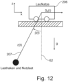
- the tower crane shown can, for example, have a tower 201 in a manner known per se, which carries a boom 202, which is balanced by a counter-boom 203, on which a counterweight 204 is provided.
- the said boom 202 can be rotated together with the counter-boom 203 about an upright axis of rotation 205, which can be coaxial with the tower axis, by a slewing gear.
- a trolley 206 can be moved on the boom 202 by a trolley drive, with a hoist rope 207 running from the trolley 206, to which a load hook 208 is attached.
- the crane can also be designed as a bridge crane.
- the crane 2 - of course also when designed as a bridge crane or other crane - can have an electronic control device 3, which can for example comprise a control computer arranged on the crane itself.
- the control device 3 mentioned can control various actuators, hydraulic circuits, electric motors, drive devices and other working units on the respective construction machine.
- these can be its hoist, its slewing gear, its trolley drive, its - if present - boom luffing drive or the like.
- the electronic control device 3 mentioned can communicate with a terminal 4, which can be arranged at the control station or in the driver's cab and can, for example, have the form of a tablet with a touchscreen and/or joysticks, rotary knobs, slide switches and similar control elements, so that on the one hand various information from the control computer 3 can be displayed on the terminal 4 and conversely control commands can be entered into the control device 3 via the terminal 4.
- a terminal 4 can be arranged at the control station or in the driver's cab and can, for example, have the form of a tablet with a touchscreen and/or joysticks, rotary knobs, slide switches and similar control elements, so that on the one hand various information from the control computer 3 can be displayed on the terminal 4 and conversely control commands can be entered into the control device 3 via the terminal 4.
- the said control device 3 of the crane 1 can in particular be designed to control the said drive devices of the hoist, the trolley and the slewing gear even when a pendulum damping device 340 detects pendulum-relevant movement parameters.
- the crane 1 can have a pendulum sensor or detection device 60 which detects an oblique pull of the hoist cable 207 and/or deflections of the load hook 208 relative to a vertical 61 which passes through the suspension point of the load hook 208, ie the trolley 206.
- the cable pull angle ⁇ can be detected against the line of gravity, ie the vertical 62, cf. Fig. 1 .
- the pendulum sensor system 60 can be attached to the trolley 206 with a camera 63 or another imaging sensor system that looks vertically downwards from the trolley 206, so that when the load hook 208 is not deflected, its image reproduction is in the center of the image provided by the camera 63.
- the load hook 208 is deflected relative to the vertical 61, for example by the trolley 206 starting up abruptly or the slewing gear braking abruptly, the image reproduction of the load hook 208 moves out of the center of the camera image, which can be determined by an image evaluation device 64.
- the diagonal pull of the hoist rope or the deflection of the load hook relative to the vertical is also accomplished with the help of an inertial measuring device IMU, which is attached to the load hook 208 and can transmit its measuring signals preferably wirelessly to a receiver on the trolley 206, cf. Fig. 10
- IMU inertial measuring device
- control device 3 can use the pendulum damping device 340 to control the slewing gear drive and control the trolley drive in order to bring the trolley 206 more or less exactly over the load hook 208 and to compensate for pendulum movements, or to reduce them or to prevent them from occurring at all.
- the pendulum damping device 340 comprises a structural dynamics sensor system 344 for determining dynamic deformations of structural components, wherein the controller module 341 of the pendulum damping device 340, which influences the control of the drive device in a pendulum-damping manner, is designed to take into account the determined dynamic deformations of the structural components of the crane when influencing the control of the drive devices.
- An estimation device 343 can also be provided, which estimates the deformations and movements of the machine structure under dynamic loads, which arise as a function of control commands entered at the control station and/or as a function of certain control actions of the drive devices and/or as a function of certain speed and/or acceleration profiles of the drive devices, taking into account conditions characterizing the crane structure.
- a calculation unit 348 can calculate the structural deformations and the resulting structural part movements using a stored calculation model as a function of the control commands entered at the control station.
- the pendulum damping device 340 uses the structural dynamics sensor system 344 to detect such elastic deformations and movements of structural components under dynamic loads.
- a sensor system 344 can, for example, comprise deformation sensors such as strain gauges on the steel structure of the crane, for example the lattice framework of the tower 201 or the boom 202.
- acceleration and/or speed sensors and/or rotation rate sensors can be provided in order to detect certain movements of structural components such as pitching movements of the boom tip or rotational dynamic effects on the boom 202.
- structural dynamics sensors can also be provided on the tower 201, in particular on its upper section on which the boom is mounted, in order to record the dynamics of the tower 201.
- motion and/or acceleration sensors can also be assigned to the drive trains in order to be able to record the dynamics of the drive trains.
- rotary encoders can be assigned to the pulleys of the trolley 206 for the hoist rope and/or pulleys for a guy rope of a luffing boom in order to be able to record the actual rope speed at the relevant point.
- the signals y (t) of the structural dynamics sensors 344 and the pendulum sensor system 60 are fed back to the controller module 341, so that a closed control loop is realized.
- the said controller module 341 influences the control signals u (t) for controlling the crane drives, in particular the slewing gear, the hoist and the trolley drive, depending on the fed-back structural dynamics and pendulum sensor signals.
- the controller structure further comprises a filter device or an observer 345 which observes the fed-back sensor signals or the crane reactions which occur with certain control variables of the drive controller and, taking into account predetermined laws of a dynamic model of the crane, which can fundamentally be of different nature and can be obtained by analysis and simulation of the steel structure, influences the control variables of the controller based on the observed crane reactions.
- a filter device or an observer 345 which observes the fed-back sensor signals or the crane reactions which occur with certain control variables of the drive controller and, taking into account predetermined laws of a dynamic model of the crane, which can fundamentally be of different nature and can be obtained by analysis and simulation of the steel structure, influences the control variables of the controller based on the observed crane reactions.
- Such a filter or observer device 345b can be designed in particular in the form of a so-called Kalman filter 346, to which the control variables u (t) of the drive controller 347 of the crane and the returned sensor signals y (t), ie the detected crane movements, in particular the cable pull angle ⁇ with respect to the vertical 62 and/or its temporal change or the angular velocity of the said diagonal pull, as well as the structural dynamic distortions of the boom 202 and the tower 201 are fed as input variables and which, from these input variables, is calculated using Kalman equations which describe the dynamic system of the Model the crane structure, in particular its steel components and drive trains, and influence the control variables of the drive controller 347 accordingly in order to achieve the desired sway-damping effect.
- Kalman filter 346 to which the control variables u (t) of the drive controller 347 of the crane and the returned sensor signals y (t), ie the detected crane movements, in particular the cable pull angle ⁇ with respect to the vertical 62 and/or its temporal change or
- Fig. 3 are shown by way of example, wherein the partial view a.) initially schematically shows a pitching deformation of the tower crane under load as a result of a bending of the tower 201 with the associated lowering of the boom 202 and an associated diagonal pull of the hoist rope.
- the partial views b.) and c.) show the Fig. 3 by way of example, in a schematic manner, a transverse deformation of the tower crane in a perspective view and in a plan view from above with the resulting deformations of the tower 201 and the boom 202.
- controller structure is designed in the form of a two-degree-of-freedom control and, in addition to the aforementioned "closed-loop" control with feedback of the pendulum sensor and structural dynamics sensor signals, comprises a feed-forward control stage 350 which, through the best possible control behavior, attempts to ideally prevent any control errors from occurring at all.
- the aforementioned feedforward control 350 is advantageously designed to be flatness-based and determined according to the so-called differential flatness method, as already mentioned at the beginning.
- the feedforward control signals u d (t) and x d (t) the structural dynamics signals and pendulum motion signals are neglected, i.e. the signals y (t) of the pendulum and structural dynamics sensors 60 and 344 respectively are not fed back to the pilot control module 350.
- the pilot control module 350 is supplied with setpoint values for the load-handling device 208, wherein these setpoint values can be position information and/or speed information and/or path parameters for the said load-handling device 208 and define the desired travel movement.
- the setpoint values for the desired load position and their time derivatives can advantageously be fed to a trajectory planning module 351 and/or a setpoint filter 352, by means of which a setpoint curve for the load position and its first four time derivatives can be determined, from which the exact curve of the necessary control signals u d (t) for controlling the drives and the exact curve u d (t) of the corresponding system states can be calculated in the pilot control module 350 using algebraic equations.
- a notch filter device 353 can advantageously be connected upstream of the feedforward control module 350 in order to filter the input variables fed to the feedforward control module 350 accordingly, wherein such a notch filter device 353 can be provided in particular between the mentioned trajectory planning module 351 or the setpoint filter module 352 on the one hand and the feedforward control module 350 on the other hand.
- the mentioned notch filter device 353 can in particular be designed to eliminate the excited natural frequencies of the structural dynamics from the setpoint signals fed to the feedforward control.
- the pendulum damping device 340 can be designed to correct the slewing gear and the trolley and, if necessary, also the lifting gear so that the The rope should always be perpendicular to the load, even if the crane tilts forward more and more due to the increasing load moment.
- the pitching movement of the crane as a result of its deformation under the load can be taken into account and the trolley can be adjusted taking into account the recorded load position or positioned with anticipatory estimation of the pitching deformation so that the hoist rope is vertically above the load when the crane deforms.
- the greatest static deformation occurs at the point where the load leaves the ground.
- the slewing gear can be adjusted taking into account the recorded load position and/or positioned with anticipatory estimation of a transverse deformation so that the hoist rope is vertically above the load when the crane deforms.
- the model underlying the pendulum-damping control can fundamentally be of different nature.
- the decoupled consideration of the dynamics in the slewing direction and within the tower-boom plane is useful.
- the slewing dynamics are stimulated and regulated by the slewing drive, while the dynamics in the tower-boom plane are stimulated and regulated by the trolley and hoist drives.
- the load swings in two directions - on the one hand across the boom (slewing direction), on the other hand in the longitudinal direction of the boom (radial). Due to the low elasticity of the hoist rope, the vertical load movement largely corresponds to the vertical boom movement, which in tower cranes is small compared to the load deflections due to the pendulum movement.
- the slewing dynamics particularly include steel structure movements such as tower torsion, boom transverse bending around the vertical axis and tower bending transverse to the boom longitudinal direction, as well as pendulum dynamics transverse to the boom and slewing gear drive dynamics.
- the radial dynamics include tower bending in the boom direction, pendulum dynamics in the boom direction and, depending on the perspective, boom bending in the vertical direction.
- the drive dynamics of the trolley and, if applicable, the hoist are also included in the radial dynamics.
- a linear design method is advantageously used, which is based on the linearization of the non-linear mechanical model equations around a rest position.
- Such linearization eliminates all couplings between the swivel and radial dynamics. This also means that no couplings are taken into account when designing a linear control, even if the model was initially derived as coupled. Both directions can be considered as decoupled from the outset, as this significantly simplifies the mechanical modeling.
- this creates a clear model in a compact form for the swivel dynamics that can be evaluated quickly, which saves computing power on the one hand and speeds up the development process of the control design on the other.
- the boom can be considered as an Euler-Bernoulli beam and thus initially as a system with distributed mass
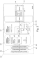
- the boom is modelled as a beam in a moving reference system, which rotates with the rotation rate ⁇ by the slewing drive, as in Fig. 4 shown.
- the Coriolis acceleration represents a bidirectional coupling between slewing and radial dynamics. This is proportional to the rotation speed of the reference system as well as to the relative speed.
- Typical maximum rotation rates of a tower crane are in the range of approx. ⁇ MAX ⁇ 0.1 rad s , which is why the Coriolis acceleration typically assumes small values compared to the driven accelerations of the tower crane.
- the rotation rate is very small, during large guide movements the Coriolis acceleration can be planned in advance and explicitly taken into account by a feedforward control. In both cases, neglecting the Coriolis acceleration leads to only small approximation errors, which is why it is neglected in the following.
- the centrifugal acceleration only affects the radial dynamics depending on the rotation rate and can be considered as a disturbance variable for this. It has little effect on the swivel dynamics due to the slow rotation rates and can therefore be neglected. However, the linear Euler acceleration is important, which acts in the tangential direction and therefore plays a central role when considering the swivel dynamics.
- the cantilever Due to the small cross-sectional area of the cantilever and small shear deformations, the cantilever can be considered as an Euler-Bernoulli beam. This means that the rotational kinetic energy of the beam rotation around the vertical axis is neglected. It is assumed that the mechanical parameters such as mass coatings and area moments of inertia of the Euler-Bernoulli approximation of the cantilever elements are known and can be used for the calculation.
- ⁇ ( x ) is the mass coating
- I ( x ) is the area moment of inertia at the point x
- E is the elastic modulus
- q ⁇ ( x,t ) is the distributed force acting on the cantilever.
- the zero point of the spatial coordinate x for this derivation is at the end of the counter cantilever.
- the notation ⁇ ′ ⁇ ⁇ ⁇ x describes the local differentiation. Damping parameters will be introduced later.
- the tower can initially be assumed to be a homogeneous Euler-Bernoulli beam.
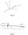
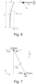
- the tower is represented at this point by a rigid body substitute model. Only one eigenmode for the tower bending and one for the tower torsion is taken into account. Since essentially only the movement at the top of the tower is relevant for the slewing dynamics, the tower dynamics can be used as a substitute system for bending or torsion by means of a spring-mass system with the same natural frequency. In the case of a higher elasticity of the tower, the spring-mass systems can be more easily supplemented with further eigenmodes at this point by adding a corresponding number of masses and springs, cf. Fig. 6 .
- the parameters spring stiffness c b and mass m T are chosen so that the deflection at the tip and the natural frequency match that of the Euler-Bernoulli beam, which represents the tower dynamics.
- a rigid body equivalent model with the inertia J T and the torsional spring stiffness c t can be derived analogously as in Fig. 5 shown.
- the payload can still be modelled as a concentrated mass point.
- the rope mass can be neglected.
- the payload is influenced somewhat more by Euler, Coriolis and centrifugal forces.
- the acceleration on the load are in Fig. 7 shown.
- the pendulum dynamics can be easily derived using the Lagrange formalism.
- the distributed parametric model (5) of the cantilever dynamics describes an infinite number of eigenmodes of the cantilever and is not yet suitable for a control design in this form. Since only a few of the lowest frequency eigenmodes are relevant for the observer and the control system, a modal transformation with subsequent modal order reduction to these few eigenmodes is recommended. However, an analytical modal transformation of equation (5) is rather difficult. Instead, it is advisable to first locally discretize equation (5) using finite differences or the finite element method and thus obtain an ordinary differential equation.
- the beam is divided into N equidistantly distributed mass points at the cantilever positions x i , i ⁇ 1 ... N
- the local derivatives are calculated using the central difference quotient w i ′ ⁇ ⁇ w i ⁇ 1 + w i + 1 2 ⁇ x w i " ⁇ w i ⁇ 1 ⁇ 2 w i + w i + 1 ⁇ x 2
- equation (35) depends on the values I -1 and I N+1 at the boundaries, which in practice can be replaced by the values I 1 and I N .
- the forces and moments with which the tower and load act on the boom can be described.
- (50) is a linear parameter variant differential equation, the concrete form of which can only be determined at runtime, especially online. This must be taken into account in the subsequent observer and control design.
- the number of discretization points N should be chosen large enough to ensure a precise description of the beam deformation and dynamics. This makes (50) a large system of differential equations. For the control, however, a modal order reduction is recommended in order to reduce the multitude of system states to a lower number.
- Modal order reduction is one of the most commonly used reduction methods.
- the basic idea is to first perform a modal transformation, i.e. to specify the dynamics of the system based on the eigenmodes (shapes) and the eigenfrequencies. Then then only the relevant eigenmodes (usually the lowest frequency ones) are selected and all higher frequency modes are neglected.
- the number of eigenmodes considered is referred to as ⁇ in the following.
- the state vector z r now only describes the few ⁇ modal amplitudes.
- the entries of the diagonal damping matrix D ⁇ r can also be determined by experimental identification.
- Fig. 8 Three of the most important eigenmodes are in Fig. 8 The top one describes the slowest eigenmode, which is dominated by the pendulum motion of the load. The second eigenmode shown shows a clear tower bend, while in the third the boom bends significantly. All eigenmodes whose natural frequencies can be excited by the slewing gear drive should be taken into account.
- the output vector y describes exactly the rotation rates, strains or accelerations that are measured by the sensors on the crane.
- Q and R represent the covariance matrices of the process and measurement noise and serve as design parameters of the Kalman filter.
- equations (60) and (61) describe a parameter-variant system
- the solution P of equation (63) is only ever valid for the corresponding parameter set ⁇ x tr ,l,m L ⁇ .
- the standard methods for solving algebraic Riccati equations are quite computationally intensive.
- the solution P for a finely resolved characteristic map in the parameters x tr ,l,m L can be precalculated offline.
- the value is then selected from the characteristic map whose parameter set ⁇ x tr ,l,m L ⁇ is closest to the current parameters.
- the vector contains x ref are the target states, which are typically all zero in the rest position (except for the angle of rotation ⁇ ). While traversing a path, the values can be non-zero, but should not deviate too far from the rest position around which the model was linearized.
- the observer dynamics (62) can be simulated on a control unit during runtime.
- the control signals are calculated from the feedback gain and the estimated state vector according to (62).
- the radial dynamics can also be represented by a linear model of the form (60)-(61), the radial dynamics can be controlled in a similar way to the slewing dynamics. Both controls then act independently of each other on the crane and stabilize the swaying dynamics in the radial direction and transversely to the boom, taking into account the drive and structural dynamics.
- ⁇ y and ⁇ y describe the angles between the rigid bodies and ⁇ y the radial pendulum angle of the load.
- P describes the positions of the centres of gravity, where the index CJ stands for the counter-jib, J for the boom, TR for the trolley and T for the tower (in this case the upper The positions depend at least partially on the values x TR and l set by the drives.
- springs At the joints between the rigid bodies there are springs with the spring stiffnesses c ⁇ ⁇ x , c ⁇ ⁇ y and dampers whose viscous friction is described by the parameters d ⁇ y and d ⁇ y .
- the dynamics can be derived using the well-known Lagrange formalism.
- the three degrees of freedom in the vector q ⁇ ⁇ y ⁇ y ⁇ y
- T kin 1 2 m T P ⁇ T 2 2 + m J P ⁇ J 2 2 + m CJ P ⁇ CJ 2 2 + m TR P ⁇ TR 2 2 + m TR P ⁇ TR 2 2 + m L P ⁇ L 2 2 as well as the potential energies due to gravity and spring stiffness
- ⁇ i describes the corresponding time constants and u i the target speeds.
- the deflection of the hoist rope relative to the vertical 62 can be determined not only by an imaging sensor on the trolley, but also by an inertial measuring device on the load hook.
- Such an inertial measuring device IMU can in particular have acceleration and rotation rate sensor means for providing acceleration and rotation rate signals, which on the one hand indicate translational accelerations along different spatial axes and on the other hand indicate rotation rates or gyroscopic signals with respect to different spatial axes.
- Rotation rates can be rotational speeds, but in principle also rotational accelerations or both.
- the inertial measuring device IMU can detect accelerations in three spatial axes and rotation rates about at least two spatial axes.
- the acceleration sensor means can be designed to work in three axes and the gyroscope sensor means can be designed to work in two axes.
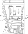
- the inertial measuring device IMU attached to the load hook can advantageously transmit its acceleration and rotation rate signals and/or signals derived therefrom wirelessly to the control and/or evaluation device 3 or its pendulum damping device 340, which is attached to a structural part of the crane. or can also be arranged separately near the crane.
- the transmission can be made to a receiver REC, which can be attached to the trolley 206 and/or to the suspension from which the hoist rope runs.
- the transmission can advantageously be made, for example, via a WLAN connection, cf. Fig. 10 .
- the load hook 208 can tilt in different directions and in different ways relative to the hoist rope 207 depending on the connection.
- the diagonal pull angle ⁇ of the hoist rope 207 does not have to be identical to the orientation of the load hook.
- the tilt angle ⁇ ⁇ describes the tilting or rotation of the load hook 207 relative to the diagonal pull ⁇ of the hoist rope 2017 or the rotation between inertial coordinates and load hook coordinates.
- the two pendulum directions in the direction of travel of the trolley i.e. in the longitudinal direction of the boom on the one hand, and in the direction of rotation or arc around the tower axis, i.e. in the direction perpendicular to the longitudinal direction of the boom, can be considered separately from one another, since these two pendulum movements hardly influence each other.
- Each pendulum direction can therefore be modeled two-dimensionally.
- the pendulum dynamics can be described using the Lagrange equations.
- the trolley position s x ( t ) , the rope length l ( t ) and the rope or pendulum angle ⁇ ( t ) are defined as a function of time t, whereby in the following, for the sake of simplicity and better readability, the time dependence is no longer specified separately by the term (t).
- the hook acceleration r ⁇ s ⁇ x ⁇ 2 ⁇ ⁇ l ⁇ cos ⁇ ⁇ l ⁇ sin ⁇ + l ⁇ ⁇ 2 sin ⁇ ⁇ l ⁇ ⁇ cos ⁇ 2 l ⁇ ⁇ ⁇ sin ⁇ ⁇ l ⁇ cos ⁇ + l ⁇ ⁇ 2 cos ⁇ + l ⁇ ⁇ sin ⁇ is not required for the derivation of the load dynamics, but is used for the design of the filter, as explained below.
- the dynamics in the y - z plane can be expressed analogously.
- T x is the time constant. If the accuracy is sufficient, no further measurement of the acceleration is required.
- the tilting direction of the load hook is described by the tilting angle ⁇ ⁇ , cf. Fig. 13 .
- the IMU measures all signals in the moving, rotating body-fixed coordinate system of the load hook, which is marked with the prefix K , while vectors in inertial coordinates are marked with I or remain without an index.
- the inertial acceleration can then be used to estimate the pendulum angle based on (107) and (103).
- Estimating the rope angle ⁇ requires an accurate estimation of the tilting of the load hook ⁇ ⁇ .
- an absolute reference value is required, since the gyroscope has limited accuracy and an initial value is unknown.
- the gyroscopic measurement is regularly overlaid by an approximately constant deviation that is inherent in the measuring principle.
- K g results from the fact that the acceleration due to gravity is measured as a fictitious upward acceleration due to the sensor principle.
- the simple structure of the linear pendulum dynamics according to (109) allows the use of various filters to estimate the orientation.
- One option is a so-called continuous-time Kalman Bucy filter, which can be adjusted by varying the process parameters and noise measurement.
- a complementary filter as in Fig. 14 shown which can be adjusted in terms of its frequency characteristics by selecting the high-pass and low-pass transfer functions.
- the complementary filter can be designed to estimate the direction of the load hook tilting ⁇ ⁇ .
- a high-pass filtering of the gyroscopic signal ⁇ ⁇ with G hp 1 ( s ) yields the offset-free rotation rate ⁇ ⁇ and, after integration, a first tilt angle estimate ⁇ ⁇ , ⁇ .
- the further estimate ⁇ ⁇ , ⁇ comes from the signal K a of the acceleration sensor.
- the basic idea of the complementary filter is to sum up or combine ⁇ ⁇ , ⁇ and ⁇ ⁇ , ⁇ , whereby the high frequencies of ⁇ ⁇ , ⁇ are weighted more heavily by using the high-pass filter and the low frequencies of ⁇ ⁇ , ⁇ are weighted more heavily by using the low-pass filter, since (115) is a good estimate for low frequencies.
- the horizontal component I g x of the acceleration due to gravity is naturally zero.
- l ⁇ ,l ⁇ can be reconstructed from the measurement of l , for example using the drive dynamics according to (108).
- the pendulum angle estimated using an extended Kalman filter (EKF) or determined using a simple static approach corresponds quite well to a validation measurement of the pendulum angle at a cardanic joint using a rotary encoder on the trolley.
- EKF extended Kalman filter
- the dynamics obviously remain the same, whereas the physical meaning and the input change.
- the obtained feedback can be determined as a linear quadratic controller (LQR), which can represent a linear quadratic Gaussian controller (LQG) structure together with the Kalman-Bucy filter. Both the feedback and the Kalman gain can be adapted to the rope length l , e.g. using gain schedules.
- LQR linear quadratic controller
- LQG linear quadratic Gaussian controller
- a structure with two degrees of freedom can be used, similar to that explained above, as in Fig. 16 shown together with a trajectory planner that provides a C 3 -differentiable reference trajectory for the load hook position.
- a change of the set point shows that the nominal error can be kept close to zero, so that the feedback signal u fb of the controller K is significantly smaller than the nominal input control variable u ff .
- the two-degree-of-freedom controller structure can comprise a trajectory planner TP that defines a smooth trajectory z ⁇ C 3 for the flat output with limited derivatives, the input variable ⁇ u and the parameterization of the state ⁇ x , as well as the controller K .
Landscapes
- Engineering & Computer Science (AREA)
- Mechanical Engineering (AREA)
- Control And Safety Of Cranes (AREA)
- Automation & Control Theory (AREA)
Applications Claiming Priority (3)
| Application Number | Priority Date | Filing Date | Title |
|---|---|---|---|
| DE102018005068.9A DE102018005068A1 (de) | 2018-06-26 | 2018-06-26 | Kran und Verfahren zum Steuern eines solchen Krans |
| EP19731917.1A EP3784616B1 (fr) | 2018-06-26 | 2019-06-13 | Grue et procédé pour commander une grue de ce type |
| PCT/EP2019/065497 WO2020001991A1 (fr) | 2018-06-26 | 2019-06-13 | Grue et procédé pour commander une grue de ce type |
Related Parent Applications (1)
| Application Number | Title | Priority Date | Filing Date |
|---|---|---|---|
| EP19731917.1A Division EP3784616B1 (fr) | 2018-06-26 | 2019-06-13 | Grue et procédé pour commander une grue de ce type |
Publications (2)
| Publication Number | Publication Date |
|---|---|
| EP4501839A2 true EP4501839A2 (fr) | 2025-02-05 |
| EP4501839A3 EP4501839A3 (fr) | 2025-04-30 |
Family
ID=66998362
Family Applications (2)
| Application Number | Title | Priority Date | Filing Date |
|---|---|---|---|
| EP24221600.0A Pending EP4501839A3 (fr) | 2018-06-26 | 2019-06-13 | Grue et procédé de commande d'une telle grue |
| EP19731917.1A Active EP3784616B1 (fr) | 2018-06-26 | 2019-06-13 | Grue et procédé pour commander une grue de ce type |
Family Applications After (1)
| Application Number | Title | Priority Date | Filing Date |
|---|---|---|---|
| EP19731917.1A Active EP3784616B1 (fr) | 2018-06-26 | 2019-06-13 | Grue et procédé pour commander une grue de ce type |
Country Status (6)
| Country | Link |
|---|---|
| US (1) | US11987476B2 (fr) |
| EP (2) | EP4501839A3 (fr) |
| CN (1) | CN112585079B (fr) |
| DE (1) | DE102018005068A1 (fr) |
| ES (1) | ES3015169T3 (fr) |
| WO (1) | WO2020001991A1 (fr) |
Families Citing this family (28)
| Publication number | Priority date | Publication date | Assignee | Title |
|---|---|---|---|---|
| US11953883B2 (en) * | 2018-09-03 | 2024-04-09 | Gerhard Finkbeiner | Lifting system and method for controlling the lifting system and control system for the lifting system |
| US11618566B1 (en) * | 2019-04-12 | 2023-04-04 | Vita Inclinata Technologies, Inc. | State information and telemetry for suspended load control equipment apparatus, system, and method |
| US11834305B1 (en) * | 2019-04-12 | 2023-12-05 | Vita Inclinata Ip Holdings Llc | Apparatus, system, and method to control torque or lateral thrust applied to a load suspended on a suspension cable |
| US11554934B1 (en) * | 2019-05-07 | 2023-01-17 | Agostino Saverio Mattoli Chiavarelli | Dynamic multi-hoist leveling control system |
| DE102020126504A1 (de) | 2020-10-09 | 2022-04-14 | Liebherr-Werk Biberach Gmbh | Hebezeug wie Kran sowie Verfahren und Vorrichtung zum Steuern eines solchen Hebezeugs |
| DE102021103320A1 (de) | 2021-02-12 | 2022-08-18 | Liebherr-Werk Biberach Gmbh | Hebezeug |
| AT17596U1 (de) * | 2021-05-14 | 2022-08-15 | Palfinger Ag | Verfahren zum Steuern und/oder Regeln eines fahrzeuggebundenen Hebezeuges |
| CN113387284A (zh) * | 2021-06-23 | 2021-09-14 | 湖南三一塔式起重机械有限公司 | 一种塔机回转速度的控制方法、系统及塔式起重机 |
| FI129740B (en) * | 2021-06-24 | 2022-08-15 | Cargotec Finland Oy | DYNAMIC BEND COMPENSATION, COORDINATED LIFTING CONTROL, AND SWIVEL PREVENTION IN CARGO HANDLING EQUIPMENT |
| CN113682966B (zh) * | 2021-07-19 | 2023-06-02 | 杭州大杰智能传动科技有限公司 | 用于智能塔吊的运行数据监控识别系统及其方法 |
| CN113772548B (zh) * | 2021-07-29 | 2024-01-19 | 余姚太平洋称重工程有限公司 | 一种基于双分量称重传感器的钢丝绳补偿方法 |
| DE102021121818A1 (de) * | 2021-08-23 | 2023-02-23 | Wolffkran Holding Ag | Turmdrehkran, Verfahren und Steuerungseinheit zum Betreiben eines Turmdrehkrans, Laufkatze und Katzfahrwerk |
| CN115793627B (zh) * | 2021-09-10 | 2026-04-14 | 威刚科技股份有限公司 | 自主移动装置的动力调整系统及其方法 |
| CN113868858B (zh) * | 2021-09-27 | 2022-07-05 | 哈尔滨理工大学 | 一种考虑绳长时变的船用起重机动力学建模方法 |
| CN114261897B (zh) * | 2021-12-27 | 2025-07-25 | 广汽本田汽车有限公司 | 汽车模具起吊状态检验方法、装置、设备及存储介质 |
| CN115196503A (zh) * | 2022-06-21 | 2022-10-18 | 大连海事大学 | 一种起重机上的细长杆件减摇抓夹装置控制系统及方法 |
| CN115092839B (zh) * | 2022-07-11 | 2025-11-14 | 厦门中塔日升信息科技有限公司 | 一种塔式起重机安全评估预警方法和系统 |
| EP4310045B1 (fr) | 2022-07-19 | 2026-04-29 | Volvo Construction Equipment AB | Machine de travail avec système d'assistance à l'opérateur et procédé d'annihilation ou d'amplification des oscillations |
| CN115824481B (zh) * | 2022-10-01 | 2024-07-02 | 同济大学 | 一种基于递归演化的实时索杆力识别方法 |
| EP4368558A1 (fr) * | 2022-11-10 | 2024-05-15 | XCMG European Research Center GmbH | Procédé de commande de la position d'un élément de charge et/ou d'une charge d'une grue maintenue par un élément de charge |
| DE102023110203A1 (de) | 2023-04-21 | 2024-10-24 | Liebherr-Werk Biberach Gmbh | Kran sowie Verfahren zum automatisierten Positionieren und/oder Verfahren des Lastaufnahmemittels eines solchen Krans |
| CN116969334B (zh) * | 2023-09-14 | 2023-12-22 | 华侨大学 | 一种多天车协同作业系统 |
| CN117446664B (zh) * | 2023-10-26 | 2024-05-07 | 渤海大学 | 一种基于快速有限时间指令滤波器的塔式起重机控制方法 |
| US20250368325A1 (en) * | 2024-06-03 | 2025-12-04 | Rockwell Collins, Inc. | Hoisting flight director mode |
| CN119160776B (zh) * | 2024-10-29 | 2025-11-11 | 中交四航工程研究院有限公司 | 一种目标物提升施工的振动控制装置 |
| CN119783458A (zh) * | 2024-12-18 | 2025-04-08 | 北京航空航天大学 | 基于ansys有限元分析的摆组件闭环动力学建模方法 |
| CN119797169A (zh) * | 2025-03-17 | 2025-04-11 | 四川迪斯卡电梯制造有限公司 | 一种用于电梯轿厢安装的吊装设备 |
| CN121470357B (zh) * | 2026-01-07 | 2026-03-20 | 山东神州机械有限公司 | 一种起重机运行姿态自适应控制方法及系统 |
Citations (7)
| Publication number | Priority date | Publication date | Assignee | Title |
|---|---|---|---|---|
| US5526946A (en) | 1993-06-25 | 1996-06-18 | Daniel H. Wagner Associates, Inc. | Anti-sway control system for cantilever cranes |
| DE10064182A1 (de) | 2000-10-19 | 2002-05-08 | Liebherr Werk Nenzing | Kran oder Bagger zum Umschlagen von einer an einem Lastseil hängenden Last mit Lastpendelungsdämpfung |
| DE10324692A1 (de) | 2003-05-30 | 2005-01-05 | Liebherr-Werk Nenzing Gmbh, Nenzing | Kran oder Bagger zum Umschlagen von einer an einem Lastseil hängenden Last mit optimierter Bewegungsführung |
| DE102009032270A1 (de) | 2009-07-08 | 2011-01-13 | Liebherr-Werk Nenzing Gmbh | Verfahren zur Ansteuerung eines Antriebs eines Kranes |
| DE202008018206U1 (de) | 2007-09-13 | 2012-01-24 | Rheinkalk Gmbh | Fahrzeug zum Einbringen alkalischer Stoffe in Gewässer |
| DE202008018260U1 (de) | 2007-05-16 | 2012-05-15 | Liebherr-Werk Nenzing Gmbh | Kransteuerung und Kran |
| EP2562125A1 (fr) | 2011-08-26 | 2013-02-27 | Liebherr-Werk Nenzing GmbH | Appareil de commande de grue |
Family Cites Families (28)
| Publication number | Priority date | Publication date | Assignee | Title |
|---|---|---|---|---|
| JPH08143273A (ja) | 1994-11-22 | 1996-06-04 | Nkk Corp | クレーンの振れ角検出方法およびクレーン用振れ角センサ |
| WO2000052627A1 (fr) * | 1999-03-01 | 2000-09-08 | North Carolina State University | Systeme et procede de surveillance de grue et de recuperation de donnees |
| US7289875B2 (en) * | 2003-11-14 | 2007-10-30 | Siemens Technology-To-Business Center Llc | Systems and methods for sway control |
| US7721967B2 (en) * | 2004-08-13 | 2010-05-25 | Arcelormittal Dofasco Inc. | Remote crane bar code system |
| DE202005002315U1 (de) * | 2005-02-11 | 2005-06-16 | Isam Ag | Vorrichtung zum Be- und/oder Entladen eines Laderaums mit Schüttgut, insbesondere zum Be- und/oder Entladen eines Laderaumes eines Schiffes mit Kohle, Erz o.dgl. |
| CN100408466C (zh) * | 2006-01-27 | 2008-08-06 | 上海振华港口机械(集团)股份有限公司 | 轮胎式龙门集装箱起重机的节能控制系统 |
| JP4840442B2 (ja) * | 2006-02-15 | 2011-12-21 | 株式会社安川電機 | 吊荷振れ止め装置 |
| DE102007041692A1 (de) * | 2007-09-03 | 2009-03-05 | Siemens Ag | Regelungseinrichtung zur Dämpfung von Pendelbewegungen einer seilgeführten Last |
| US8235229B2 (en) * | 2008-01-31 | 2012-08-07 | Georgia Tech Research Corporation | Methods and systems for double-pendulum crane control |
| JP5215725B2 (ja) * | 2008-05-13 | 2013-06-19 | 株式会社キトー | 走行クレーンの操作制御装置、操作制御方法 |
| US8242730B2 (en) * | 2008-06-10 | 2012-08-14 | Nichols Michael J | Automated robot teach tool and method of use |
| CN101723239B (zh) | 2009-11-20 | 2012-05-02 | 三一汽车制造有限公司 | 吊钩姿态检测装置和起重机 |
| DE102011001112A1 (de) | 2011-03-04 | 2012-09-06 | Schneider Electric Automation Gmbh | Verfahren und Steuerungseinrichtung zur schwingungsarmen Bewegung eines bewegbaren Kranelementes eines Kransystems |
| FI20115922A0 (fi) * | 2011-09-20 | 2011-09-20 | Konecranes Oyj | Nosturin ohjaus |
| CN104487377B (zh) * | 2012-05-09 | 2018-02-23 | 马尼托瓦克起重机有限责任公司 | 起重机监视系统 |
| CN103213902B (zh) * | 2013-01-10 | 2015-10-07 | 林汉丁 | 吊钩偏角检监测、协同方监测、磁方位监测装置及起重机 |
| DE102013011718A1 (de) * | 2013-07-15 | 2015-01-15 | Isam Ag | Verfahren zur Steuerung einer Containerbrücke zum Be- oder Entladen, insbesondere des Laderaumes, eines Schiffes bzw. Steuersystem zur Steuerung einer Containerbrücke bzw. Containerbrücke mit Steuersystem |
| JP2015075790A (ja) * | 2013-10-04 | 2015-04-20 | 株式会社タダノ | 作業機の位置情報管理システム |
| FI127437B (en) * | 2013-12-13 | 2018-06-15 | Konecranes Global Corp | Wireless communication with the load handler |
| TWI530375B (zh) * | 2014-02-05 | 2016-04-21 | 廣明光電股份有限公司 | 機器手臂的教導裝置及方法 |
| JP6246319B2 (ja) * | 2014-03-06 | 2017-12-13 | 住友建機株式会社 | ショベル |
| JP6454856B2 (ja) | 2015-05-27 | 2019-01-23 | 多摩川精機株式会社 | 姿勢検出装置及び姿勢検出方法 |
| DE102016004350A1 (de) * | 2016-04-11 | 2017-10-12 | Liebherr-Components Biberach Gmbh | Kran und Verfahren zum Steuern eines solchen Krans |
| DE102017114789A1 (de) * | 2017-07-03 | 2019-01-03 | Liebherr-Components Biberach Gmbh | Kran und Verfahren zum Steuern eines solchen Krans |
| DE102017117662A1 (de) | 2017-08-03 | 2019-02-07 | Konecranes Global Corporation | Verfahren zum Heben und/oder Senken eines Lastaufnahmemittels eines Hebezeugs, insbesondere eines Krans, und Hebezeug hierfür |
| US11654778B2 (en) * | 2020-03-06 | 2023-05-23 | Nissan Motor Co., Ltd. | Electric vehicle control method and electric vehicle control device |
| WO2022103427A1 (fr) * | 2020-11-12 | 2022-05-19 | Innopeak Technology, Inc. | Correction de couleur d'une fusion d'image dans un domaine de luminance |
| JP7086245B1 (ja) * | 2021-03-18 | 2022-06-17 | 三菱電機株式会社 | 進路生成装置および車両制御装置 |
-
2018
- 2018-06-26 DE DE102018005068.9A patent/DE102018005068A1/de active Pending
-
2019
- 2019-06-13 CN CN201980043661.3A patent/CN112585079B/zh active Active
- 2019-06-13 US US17/256,205 patent/US11987476B2/en active Active
- 2019-06-13 ES ES19731917T patent/ES3015169T3/es active Active
- 2019-06-13 EP EP24221600.0A patent/EP4501839A3/fr active Pending
- 2019-06-13 WO PCT/EP2019/065497 patent/WO2020001991A1/fr not_active Ceased
- 2019-06-13 EP EP19731917.1A patent/EP3784616B1/fr active Active
Patent Citations (9)
| Publication number | Priority date | Publication date | Assignee | Title |
|---|---|---|---|---|
| US5526946A (en) | 1993-06-25 | 1996-06-18 | Daniel H. Wagner Associates, Inc. | Anti-sway control system for cantilever cranes |
| DE10064182A1 (de) | 2000-10-19 | 2002-05-08 | Liebherr Werk Nenzing | Kran oder Bagger zum Umschlagen von einer an einem Lastseil hängenden Last mit Lastpendelungsdämpfung |
| DE10324692A1 (de) | 2003-05-30 | 2005-01-05 | Liebherr-Werk Nenzing Gmbh, Nenzing | Kran oder Bagger zum Umschlagen von einer an einem Lastseil hängenden Last mit optimierter Bewegungsführung |
| EP1628902A1 (fr) | 2003-05-30 | 2006-03-01 | Liebherr-Werk Nenzing GmbH | Grue ou excavatrice destinee a la manipulation d'une charge suspendue a un cable presentant un systeme de guidage optimise |
| DE202008018260U1 (de) | 2007-05-16 | 2012-05-15 | Liebherr-Werk Nenzing Gmbh | Kransteuerung und Kran |
| DE202008018206U1 (de) | 2007-09-13 | 2012-01-24 | Rheinkalk Gmbh | Fahrzeug zum Einbringen alkalischer Stoffe in Gewässer |
| DE102009032270A1 (de) | 2009-07-08 | 2011-01-13 | Liebherr-Werk Nenzing Gmbh | Verfahren zur Ansteuerung eines Antriebs eines Kranes |
| EP2562125A1 (fr) | 2011-08-26 | 2013-02-27 | Liebherr-Werk Nenzing GmbH | Appareil de commande de grue |
| US20130161279A1 (en) | 2011-08-26 | 2013-06-27 | Liebherr-Werk Nenzing Gmbh | Crane control apparatus |
Non-Patent Citations (3)
| Title |
|---|
| ARNOLD, E.NEUPERT, JSAWODNY, O.: "Modell-prädiktive Trajektoriengenerierung für flachheitsbasierte Folgeregelungen am Beispiel eines Hafenmobilkrans", AUTOMATISIERUNGSTECHNIK, vol. 8, 2008, pages 56 |
| E. ARNOLDO. SAWODNYJ. NEUPERTK. SCHNEIDER: "IEEE International Conference Mechatronics and Automation", vol. 3, 2005, article "Anti-sway system for boom cranes based on a model predictive control approach", pages: 1533 - 1538 |
| J. NEUPERTE. ARNOLDK. SCHNEIDERO. SAWODNY: "Tracking and anti-sway control for boom cranes", CONTROL ENGINEERING PRACTICE, vol. 18, 2010, pages 31 - 44 |
Also Published As
| Publication number | Publication date |
|---|---|
| EP3784616B1 (fr) | 2024-12-25 |
| CN112585079A (zh) | 2021-03-30 |
| EP3784616A1 (fr) | 2021-03-03 |
| EP4501839A3 (fr) | 2025-04-30 |
| US20210122615A1 (en) | 2021-04-29 |
| WO2020001991A1 (fr) | 2020-01-02 |
| ES3015169T3 (en) | 2025-04-29 |
| US11987476B2 (en) | 2024-05-21 |
| CN112585079B (zh) | 2023-08-04 |
| DE102018005068A1 (de) | 2020-01-02 |
Similar Documents
| Publication | Publication Date | Title |
|---|---|---|
| EP3784616B1 (fr) | Grue et procédé pour commander une grue de ce type | |
| EP3649072B1 (fr) | Grue et procédé de commande d'une telle grue | |
| EP4013713B1 (fr) | Grue et procédé de commande d'une telle grue | |
| EP2272784B1 (fr) | Grue pour envelopper une charge suspendue à un câble porteur | |
| EP1326798B1 (fr) | Grue ou excavateur pour retourner une charge suspendue a un cable porteur avec amortissement du mouvement pendulaire de la charge | |
| EP3408208B1 (fr) | Grue et procédé de commande de ladite grue | |
| EP2502871B1 (fr) | Commande de grue, grue et procédé | |
| EP3408211B1 (fr) | Grue | |
| AT520008B1 (de) | Verfahren zum Dämpfen von Drehschwingungen eines Lastaufnahmeelements einer Hebeeinrichtung | |
| DE19907989B4 (de) | Verfahren zur Bahnregelung von Kranen und Vorrichtung zum bahngenauen Verfahren einer Last | |
| EP2878566B1 (fr) | Procédé d'influence d'un mouvement d'une charge logée au niveau d'une grue | |
| EP1992583B1 (fr) | Grue avec commande de grue | |
| DE102007038016A1 (de) | Drehleiter | |
| DE102015100669A1 (de) | Anti-pendel-steuerverfahren mit einstellbarer unterstützung für den transport einer schwebenden last | |
| DE102005042721A1 (de) | Gelenkleiter oder Hubbühne mit Bahnsteuerung und aktiver Schwingungsdämpfung | |
| DE10029579B4 (de) | Verfahren zur Orientierung der Last in Krananlagen | |
| WO2023025643A1 (fr) | Grue à tour pivotante, procédé et unité de commande pour faire fonctionner une grue à tour pivotante, chariot roulant et mécanisme de roulement pour chariot | |
| WO2024156497A1 (fr) | Procédé et dispositif d'actionnement d'une grue à flèche orientable, et grue à flèche orientable | |
| DE202023002939U1 (de) | Vorrichtung zum Betreiben eines Auslegerdrehkrans sowie Auslegerdrehkran | |
| EP3326957A1 (fr) | Procédé de fonctionnement d'une grue | |
| DE29923565U1 (de) | Lasthebesystem zur Feinpositionierung und aktiven Schwingungsdämpfung |
Legal Events
| Date | Code | Title | Description |
|---|---|---|---|
| PUAI | Public reference made under article 153(3) epc to a published international application that has entered the european phase |
Free format text: ORIGINAL CODE: 0009012 |
|
| STAA | Information on the status of an ep patent application or granted ep patent |
Free format text: STATUS: THE APPLICATION HAS BEEN PUBLISHED |
|
| AC | Divisional application: reference to earlier application |
Ref document number: 3784616 Country of ref document: EP Kind code of ref document: P |
|
| AK | Designated contracting states |
Kind code of ref document: A2 Designated state(s): AL AT BE BG CH CY CZ DE DK EE ES FI FR GB GR HR HU IE IS IT LI LT LU LV MC MK MT NL NO PL PT RO RS SE SI SK SM TR |
|
| PUAL | Search report despatched |
Free format text: ORIGINAL CODE: 0009013 |
|
| AK | Designated contracting states |
Kind code of ref document: A3 Designated state(s): AL AT BE BG CH CY CZ DE DK EE ES FI FR GB GR HR HU IE IS IT LI LT LU LV MC MK MT NL NO PL PT RO RS SE SI SK SM TR |
|
| RIC1 | Information provided on ipc code assigned before grant |
Ipc: B66C 13/06 20060101AFI20250321BHEP |
|
| STAA | Information on the status of an ep patent application or granted ep patent |
Free format text: STATUS: REQUEST FOR EXAMINATION WAS MADE |
|
| 17P | Request for examination filed |
Effective date: 20251030 |
|
| GRAP | Despatch of communication of intention to grant a patent |
Free format text: ORIGINAL CODE: EPIDOSNIGR1 |
|
| STAA | Information on the status of an ep patent application or granted ep patent |
Free format text: STATUS: GRANT OF PATENT IS INTENDED |
|
| INTG | Intention to grant announced |
Effective date: 20260224 |