EP4501842A1 - Procédé et installation de production d'hydrogène - Google Patents
Procédé et installation de production d'hydrogène Download PDFInfo
- Publication number
- EP4501842A1 EP4501842A1 EP23020365.5A EP23020365A EP4501842A1 EP 4501842 A1 EP4501842 A1 EP 4501842A1 EP 23020365 A EP23020365 A EP 23020365A EP 4501842 A1 EP4501842 A1 EP 4501842A1
- Authority
- EP
- European Patent Office
- Prior art keywords
- reaction zone
- steam reforming
- hydrogen
- gas
- carbon dioxide
- Prior art date
- Legal status (The legal status is an assumption and is not a legal conclusion. Google has not performed a legal analysis and makes no representation as to the accuracy of the status listed.)
- Withdrawn
Links
Images


Classifications
-
- C—CHEMISTRY; METALLURGY
- C01—INORGANIC CHEMISTRY
- C01B—NON-METALLIC ELEMENTS; COMPOUNDS THEREOF; METALLOIDS OR COMPOUNDS THEREOF NOT COVERED BY SUBCLASS C01C
- C01B3/00—Hydrogen; Gaseous mixtures containing hydrogen; Separation of hydrogen from mixtures containing it; Purification of hydrogen; Reversible storage of hydrogen
- C01B3/02—Production of hydrogen; Production of gaseous mixtures containing hydrogen
- C01B3/32—Production of hydrogen; Production of gaseous mixtures containing hydrogen by reaction of gaseous or liquid organic compounds with gasifying agents, e.g. water, carbon dioxide or air
- C01B3/34—Production of hydrogen; Production of gaseous mixtures containing hydrogen by reaction of gaseous or liquid organic compounds with gasifying agents, e.g. water, carbon dioxide or air by reaction of hydrocarbons with gasifying agents
- C01B3/38—Production of hydrogen; Production of gaseous mixtures containing hydrogen by reaction of gaseous or liquid organic compounds with gasifying agents, e.g. water, carbon dioxide or air by reaction of hydrocarbons with gasifying agents using catalysts
- C01B3/382—Processes with two or more reaction steps, of which at least one is catalytic, e.g. steam reforming and partial oxidation
-
- C—CHEMISTRY; METALLURGY
- C01—INORGANIC CHEMISTRY
- C01B—NON-METALLIC ELEMENTS; COMPOUNDS THEREOF; METALLOIDS OR COMPOUNDS THEREOF NOT COVERED BY SUBCLASS C01C
- C01B3/00—Hydrogen; Gaseous mixtures containing hydrogen; Separation of hydrogen from mixtures containing it; Purification of hydrogen; Reversible storage of hydrogen
- C01B3/50—Separation of hydrogen or hydrogen-containing gases from gaseous mixtures, e.g. purification
-
- C—CHEMISTRY; METALLURGY
- C01—INORGANIC CHEMISTRY
- C01B—NON-METALLIC ELEMENTS; COMPOUNDS THEREOF; METALLOIDS OR COMPOUNDS THEREOF NOT COVERED BY SUBCLASS C01C
- C01B2203/00—Integrated processes for the production of hydrogen or synthesis gas
- C01B2203/02—Processes for making hydrogen or synthesis gas
- C01B2203/0205—Processes for making hydrogen or synthesis gas containing a reforming step
- C01B2203/0227—Processes for making hydrogen or synthesis gas containing a reforming step containing a catalytic reforming step
- C01B2203/0233—Processes for making hydrogen or synthesis gas containing a reforming step containing a catalytic reforming step the reforming step being a steam reforming step
-
- C—CHEMISTRY; METALLURGY
- C01—INORGANIC CHEMISTRY
- C01B—NON-METALLIC ELEMENTS; COMPOUNDS THEREOF; METALLOIDS OR COMPOUNDS THEREOF NOT COVERED BY SUBCLASS C01C
- C01B2203/00—Integrated processes for the production of hydrogen or synthesis gas
- C01B2203/02—Processes for making hydrogen or synthesis gas
- C01B2203/0283—Processes for making hydrogen or synthesis gas containing a CO-shift step, i.e. a water gas shift step
- C01B2203/0288—Processes for making hydrogen or synthesis gas containing a CO-shift step, i.e. a water gas shift step containing two CO-shift steps
-
- C—CHEMISTRY; METALLURGY
- C01—INORGANIC CHEMISTRY
- C01B—NON-METALLIC ELEMENTS; COMPOUNDS THEREOF; METALLOIDS OR COMPOUNDS THEREOF NOT COVERED BY SUBCLASS C01C
- C01B2203/00—Integrated processes for the production of hydrogen or synthesis gas
- C01B2203/04—Integrated processes for the production of hydrogen or synthesis gas containing a purification step for the hydrogen or the synthesis gas
- C01B2203/0415—Purification by absorption in liquids
-
- C—CHEMISTRY; METALLURGY
- C01—INORGANIC CHEMISTRY
- C01B—NON-METALLIC ELEMENTS; COMPOUNDS THEREOF; METALLOIDS OR COMPOUNDS THEREOF NOT COVERED BY SUBCLASS C01C
- C01B2203/00—Integrated processes for the production of hydrogen or synthesis gas
- C01B2203/04—Integrated processes for the production of hydrogen or synthesis gas containing a purification step for the hydrogen or the synthesis gas
- C01B2203/042—Purification by adsorption on solids
- C01B2203/043—Regenerative adsorption process in two or more beds, one for adsorption, the other for regeneration
-
- C—CHEMISTRY; METALLURGY
- C01—INORGANIC CHEMISTRY
- C01B—NON-METALLIC ELEMENTS; COMPOUNDS THEREOF; METALLOIDS OR COMPOUNDS THEREOF NOT COVERED BY SUBCLASS C01C
- C01B2203/00—Integrated processes for the production of hydrogen or synthesis gas
- C01B2203/04—Integrated processes for the production of hydrogen or synthesis gas containing a purification step for the hydrogen or the synthesis gas
- C01B2203/0465—Composition of the impurity
- C01B2203/0475—Composition of the impurity the impurity being carbon dioxide
-
- C—CHEMISTRY; METALLURGY
- C01—INORGANIC CHEMISTRY
- C01B—NON-METALLIC ELEMENTS; COMPOUNDS THEREOF; METALLOIDS OR COMPOUNDS THEREOF NOT COVERED BY SUBCLASS C01C
- C01B2203/00—Integrated processes for the production of hydrogen or synthesis gas
- C01B2203/08—Methods of heating or cooling
- C01B2203/0805—Methods of heating the process for making hydrogen or synthesis gas
-
- C—CHEMISTRY; METALLURGY
- C01—INORGANIC CHEMISTRY
- C01B—NON-METALLIC ELEMENTS; COMPOUNDS THEREOF; METALLOIDS OR COMPOUNDS THEREOF NOT COVERED BY SUBCLASS C01C
- C01B2203/00—Integrated processes for the production of hydrogen or synthesis gas
- C01B2203/08—Methods of heating or cooling
- C01B2203/0872—Methods of cooling
- C01B2203/0877—Methods of cooling by direct injection of fluid
-
- C—CHEMISTRY; METALLURGY
- C01—INORGANIC CHEMISTRY
- C01B—NON-METALLIC ELEMENTS; COMPOUNDS THEREOF; METALLOIDS OR COMPOUNDS THEREOF NOT COVERED BY SUBCLASS C01C
- C01B2203/00—Integrated processes for the production of hydrogen or synthesis gas
- C01B2203/12—Feeding the process for making hydrogen or synthesis gas
- C01B2203/1205—Composition of the feed
- C01B2203/1211—Organic compounds or organic mixtures used in the process for making hydrogen or synthesis gas
- C01B2203/1235—Hydrocarbons
-
- C—CHEMISTRY; METALLURGY
- C01—INORGANIC CHEMISTRY
- C01B—NON-METALLIC ELEMENTS; COMPOUNDS THEREOF; METALLOIDS OR COMPOUNDS THEREOF NOT COVERED BY SUBCLASS C01C
- C01B2203/00—Integrated processes for the production of hydrogen or synthesis gas
- C01B2203/14—Details of the flowsheet
- C01B2203/142—At least two reforming, decomposition or partial oxidation steps in series
-
- C—CHEMISTRY; METALLURGY
- C01—INORGANIC CHEMISTRY
- C01B—NON-METALLIC ELEMENTS; COMPOUNDS THEREOF; METALLOIDS OR COMPOUNDS THEREOF NOT COVERED BY SUBCLASS C01C
- C01B2203/00—Integrated processes for the production of hydrogen or synthesis gas
- C01B2203/14—Details of the flowsheet
- C01B2203/142—At least two reforming, decomposition or partial oxidation steps in series
- C01B2203/143—Three or more reforming, decomposition or partial oxidation steps in series
-
- C—CHEMISTRY; METALLURGY
- C01—INORGANIC CHEMISTRY
- C01B—NON-METALLIC ELEMENTS; COMPOUNDS THEREOF; METALLOIDS OR COMPOUNDS THEREOF NOT COVERED BY SUBCLASS C01C
- C01B2203/00—Integrated processes for the production of hydrogen or synthesis gas
- C01B2203/16—Controlling the process
- C01B2203/1614—Controlling the temperature
-
- C—CHEMISTRY; METALLURGY
- C01—INORGANIC CHEMISTRY
- C01B—NON-METALLIC ELEMENTS; COMPOUNDS THEREOF; METALLOIDS OR COMPOUNDS THEREOF NOT COVERED BY SUBCLASS C01C
- C01B2203/00—Integrated processes for the production of hydrogen or synthesis gas
- C01B2203/16—Controlling the process
- C01B2203/1628—Controlling the pressure
Definitions
- the invention relates to a process and a plant for producing hydrogen.
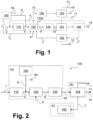
- FIG. 1 illustrates a conventional steam reforming process (Steam Methane Reforming, SMR) in the form of a block diagram.
- SMR Steam Methane Reforming
- FIG. 1 a feed pretreatment 110, a steam reforming 120, a water gas shift 130, a hydrogen purification 140, a heat recovery 150 and a steam system 160 are illustrated, wherein the correspondingly designated elements can each also stand for one or more units which are set up for the aforementioned steps.
- a carbon dioxide removal 101, 102 and 103 is shown at three locations, which can each be optional or, in the case of carbon dioxide removals 101 and 102, also alternative to each other.
- a hydrocarbon-containing material stream 1 for example natural gas, is divided into a feed stream 2 and a fuel gas stream 3, wherein the feed stream 2 is combined with a recycled hydrogen stream 4 obtained downstream of the hydrogen purification 140.
- a suitably pretreated feed stream 5 is combined with a steam stream 6 from the steam system 160, which can also provide, for example, export steam 6a, and fed into the steam reforming 120, which is operated using one or more fired reactors 120a.
- the fuel gas stream 3 and an exhaust gas 7 obtained in the hydrogen purification 140 are burned with combustion air 8.
- the energy for the strongly endothermic reaction in the steam reforming 120 is thus provided by the combustion of fossil fuel, e.g. natural gas, in the form of the fuel gas stream 3.
- a water gas shift 130 which may comprise one or more shift reactors or shift stages, in order to convert carbon monoxide and water into hydrogen and carbon dioxide and thereby increase the hydrogen yield.
- Shifted synthesis gas 10 is taken from the water gas shift 130, processed in the carbon dioxide removal 101, if present, to separate a carbon dioxide stream 11, and fed to the hydrogen purification 140, which can be carried out, for example, using pressure swing adsorption (PSA) or in another known manner.
- PSA pressure swing adsorption
- the aforementioned exhaust gas 7 is obtained, which, depending on whether the carbon dioxide removal 101 was carried out or not, can contain considerable amounts of carbon dioxide in addition to methane, carbon monoxide and hydrogen. Depending on this, the carbon dioxide removal 102 can be carried out, whereby a carbon dioxide stream 12 is separated. Even if a carbon dioxide removal 102 is carried out, the exhaust gas 7 is also referred to as 7 downstream of this for reasons of clarity. Furthermore, in the hydrogen purification 140, a hydrogen product stream 14 is formed, from which the previously mentioned, recirculated hydrogen stream 4 can be branched off.
- a flue gas 15 from the combustion chamber of a reactor used in the steam reforming 120 is subjected to heat recovery 150 and then, if present, to obtain a carbon dioxide stream 13 on the one hand and a low-carbon dioxide or at least carbon dioxide-depleted flue gas 16 is subjected to carbon dioxide removal 103.
- the capture methods for carbon dioxide include absorption (e.g. by amine scrubbing), adsorption (e.g. by the applicant's Hisorp ® CC technology), membrane processes or corresponding combinations.
- an acceptable capture rate of 90% or more of the total carbon dioxide formed in the process can be achieved by carbon dioxide removal 103 in the flue gas 15 (post combustion capture, PCC), since a significant proportion of the emissions arise during combustion, whereby the offgas is also burned after purification 140 and the resulting carbon dioxide is also separated in the flue gas.
- carbon capture in the flue gas 15 is very energy-intensive due to the low partial pressure of carbon dioxide, causes additional investment costs for the process and can lead to undesirable amine emissions.
- E-SMR electrically heated reforming
- the electrically heated reforming also has the advantage that it can be operated at a higher temperature of up to 1100 °C compared to conventional steam reforming, which leads to a lower methane slip in the synthesis gas 9.
- the exhaust gas 7 from the hydrogen purification 140 can be burned in a suitable device in order to use the hot flue gas to preheat the inlet streams into the steam reforming 120, for example. In order to achieve a high carbon dioxide removal rate, the carbon dioxide emissions from this combustion must be minimized.
- flue gas 15 is no longer produced by the combustion of fuel gas 3 for heating the steam reforming 120, which is the crucial difference to conventional steam reforming.
- the vast majority of the carbon dioxide produced in the process is contained in the process gas 10, from which it can be separated much more economically at a higher partial pressure than from the flue gas 15.
- the concepts proposed here comprise an electrically heated reforming process for producing hydrogen, with a separation of carbon dioxide from the synthesis gas and/or the exhaust gas of the hydrogen purification (e.g. by pressure swing adsorption) and the disposal of the separated carbon dioxide by sequestration and/or material utilization.
- the invention and its embodiments provide concepts with high efficiency, reduced feedstock consumption, minimal direct emissions of carbon dioxide and advantageous separation rates (i.e. low overall production rates of carbon dioxide).
- preferred operating conditions such as reactor temperature and steam-carbon ratio are specified, which are advantageous for the proposed concepts.
- a method for producing hydrogen is proposed in which a hydrocarbon-containing feed stream is subjected to steam reforming, the steam reforming being carried out using a reaction arrangement which has a first reaction zone to which heat generated using electrical current is supplied.
- the present invention and its embodiments therefore relate to electrically heated reforming.
- the process gas obtained in the first reaction zone is treated in a second reaction zone without the addition of heat.
- the second reaction zone arranged downstream of the first reaction zone can thus be operated adiabatically or it can be arranged in a device by means of which heat is transferred to another material stream, in particular to a feed stream in the steam reforming.
- the second reaction zone which comprises a catalyst suitable for steam reforming, can be provided in an adiabatic reactor or in passages of a heat transfer device provided for the synthesis gas.
- the second reaction zone downstream of the first allows a reduction in the distance to the reaction equilibrium, which compensates for a deactivation of the catalyst bed or an unfavourable distribution (maldistribution) of the flows in the actual reformer, ie the first reaction zone, and a corresponding electrically heated reformer can be designed to be particularly compact.
- the concentrations at the outlet from the steam reforming or a corresponding reactor should be as close as possible to the reaction equilibrium in order to increase the efficiency of the reforming and reduce direct carbon dioxide emissions.
- the catalyst in the second reaction zone can be in the form of conventional nickel-based catalyst pellets, which either have a suitable, in particular inert, support or consist of solid material.
- components coated with catalyst or a design corresponding to the first reaction zone without electrical heating can also be used as the second reaction zone.
- Advantages are also achieved by using a heat transfer device with a catalyst, in which heat is transferred to another material stream, in particular to a feed stream in the steam reforming.
- heat can be transferred from the process gas flowing out of the first or second reaction zone or directly from the second reaction zone to another material stream, which is in particular at least part of the hydrocarbon-containing feed stream in the steam reforming. Since such a heat transfer device has a catalyst on the process gas side, it is also referred to below as a heat transfer reactor.
- the second reaction zone can therefore in particular be designed as part of a feed-effluent heat exchanger and equipped with a suitable catalyst.
- a feed-effluent heat exchanger can also be used, in which catalyst material is only on the process gas side or on both sides of the heat transfer surface.
- the reaction device which can be used for steam reforming can also have a third reaction zone upstream of the first reaction zone, wherein at least two of the reaction zones are provided with the same catalyst or all reaction zones are provided with different catalysts.
- the third reaction zone can also be set up for pre-reforming. It can be provided in different designs and can be heated, for example, electrically or by a gas stream or operated adiabatically with a preheated insert.
- the third reaction zone is preferably arranged in a passage of a feed-effluent heat exchanger which also includes the second reaction zone.
- the catalyst used in the first reaction zone can contain nickel, for example, and be attached to a ceramic carrier or the reactor wall, whereas in the second and possibly third reaction zone a solid material is typically used.
- steam reforming can be carried out in particular at 950 or 1000 to 1100 °C, with these temperatures being present in particular at an outlet from the first reaction zone.
- the methane conversion can be increased in particular.
- a reduction in the conversion loss is possible, so that synergies arise.
- a ratio of steam to carbon of more than 2.5 or 4.0 and up to 4.5 (in mol/mol) can be set. In this way, high conversions can be achieved and the risk of coke formation in steam reforming can be minimized.
- the steam reforming can be carried out at a pressure of over 25 bar, 50 bar or 75 bar and up to 100 bar. In other embodiments, however, lower pressure values from atmospheric pressure to 25 bar, from 10 to 20 bar or from 10 to 15 bar can also be used.
- a synthesis gas formed using steam reforming is subjected to a water gas shift, which comprises a high-temperature shift stage and a low-temperature shift stage.
- Isoshift stages can also be provided.
- An isoshift stage is characterized by the fact that it is not operated adiabatically, but isothermally. This Reaction heat is removed and more carbon monoxide is shifted to carbon dioxide (lower exit temperature) compared to an adiabatic shift stage.
- Water is used for cooling, for example, and steam is generated accordingly, which can be used for the process, exported or used for heating, for example for amine washing or the like.
- a synthesis gas formed using steam reforming can be subjected to carbon dioxide removal and hydrogen separation, in particular downstream of the water gas shift, with different embodiments and their advantages being explained further below.
- the carbon dioxide removal can be arranged upstream of the hydrogen removal and a residual gas stream formed in the hydrogen removal can be at least partially recycled to the hydrogen removal.
- the hydrogen removal can comprise a first hydrogen removal stage and a second hydrogen removal stage. In other embodiments, the carbon dioxide removal can be arranged downstream of the hydrogen removal.
- the proposed plant for producing hydrogen is designed to subject a hydrocarbon-containing feed stream to steam reforming and to carry out the steam reforming using a reaction arrangement which has a first reaction zone to which heat generated using electrical current can be supplied. It is provided that the reaction arrangement has a second reaction zone downstream of the first reaction zone, which is designed to treat a process gas obtainable in the first reaction zone without supplying heat.
- the second reaction zone can be arranged in an adiabatic reactor or a passage of a heat exchanger.
- Different embodiments of the invention may include, have, consist of, or consist essentially of other useful combinations of the described elements, components, features, parts, steps, means, etc., even if such combinations are not specifically described herein.
- the disclosure may include other inventions that are not currently claimed, but that may be claimed in the future, particularly if they are included within the scope of the independent claims.
- Figure 1 illustrates a method for steam reforming according to an embodiment not according to the invention in the form of a schematic process diagram, which has already been explained in detail at the beginning. Reference is made to the above explanations. The corresponding reference numerals are also used in part in the figures explained below, in particular to illustrate the integration of the components illustrated there.
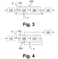
- FIG 2 is a general flow diagram of an electrically heated reforming for hydrogen production according to an embodiment of the invention and is designated as a whole by 100.
- the material flows or process steps and apparatus according to Figure 1 The corresponding material flows or process steps and equipment are identical to those described there, whereby reference is also made to some of the above explanations.
- a hydrogen recycling comparable to stream 4 in Figure 1 can also be provided here and is only omitted for the sake of clarity.
- the electrically heated steam reforming like the fired steam reforming according to Figure 1 , hereinafter also referred to as 120.
- the entire system according to Figure 2 which comprises the steam reforming 120 operated with electrical current P, is divided into three blocks, each of which is outlined with dashed lines: This is the core process with the reaction part or the steam reforming 120 according to block A, a combined hydrogen purification and carbon dioxide removal 104 according to block B, and an exhaust gas utilization or exhaust gas integration 180 according to block C.
- the blocks mentioned do not have to be combined in corresponding structural units.
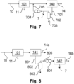
- the steam reforming 120 can be carried out using a reaction arrangement 200 which has a first reaction zone 210 and a second reaction zone 220, wherein the two reaction zones 210 and 220 each have a catalyst. It can be the same catalyst or different catalysts, in particular nickel-containing catalysts.
- the second reaction zone 220 While the first reaction zone 210 is supplied with electrical energy P or the heat generated thereby, the second reaction zone 220 is operated adiabatically, i.e. no more energy is supplied to it.
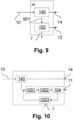
- the second reaction zone 220 is part of a feed-effluent heat exchanger reactor. Heat is therefore transferred to the reaction feed.
- the feed-effluent heat exchanger reactor can also contain a third reaction zone with catalyst at least partially on the side of the reaction feed. Further aspects of the present invention and its embodiments are explained in more detail below.
- Optimized process conditions and concepts to increase methane conversion and minimize the off-gas rate include operating the electrically heated reforming at high temperatures of up to 1100 °C, which, as mentioned, leads to higher methane conversion (i.e., lower methane slip) compared to conventional steam reforming.
- FIG. 5 shows a graph in which a methane conversion X in percent on the vertical axis is plotted against a reforming temperature T in degrees Celsius on the horizontal axis.
- the upper data points give values for a steam to carbon ratio (S/C) of 2.8 at a pressure of 15 bar, the lower data points give results for a steam to carbon ratio of 2.8 at a pressure of 30 bar.
- Vertical lines 501 and 502 at 900 and 1050 °C serve to illustrate the differences.
- the circled points 501a and 501b on line 501 mark the methane conversions achieved at a low, non-preferred temperature (900 °C) and at the same time illustrate a large conversion loss when increasing the operating pressure (here from 15 bar to 30 bar) at this operating temperature.
- the circled points 502a and 502b on line 502 indicate the methane conversions achieved at a high, preferred temperature (1050 °C) and at the same time illustrate a lower conversion loss when the operating pressure is increased from 15 bar to 30 bar.
- Arrow 503 indicates an approach to equilibrium (ATE) of 100 K based on 501b. It can be seen that the conversion loss at an operating temperature of 900 °C is very high compared to an ATE of 100 K based on 502a and 502b.
- Methane conversion is therefore favored at low pressures, but especially at high temperatures due to the flattening of the data points with increasing temperature. High operating temperatures thus compensate for the conversion loss at a greater distance from equilibrium.
- Methane conversion is also favored at high steam to carbon ratios. This is in Figure 6 which also shows a diagram in which a methane conversion X in percent is plotted on the vertical axis against a reforming temperature T in degrees Celsius on the horizontal axis. The rows of data points give values for Values of the steam to carbon ratio of 1, 1.5, 2, 2.5 and 3 at a pressure of 20 bar each.
- high temperature operation above 1000 °C is used to increase methane conversion. If the ATE is high, high temperature operation can reduce conversion loss. However, if the ATE is low (below 10 K), lower temperatures starting at 950 °C can be beneficial in terms of lifetime and material choice. In addition, even higher reaction temperatures (more than 1100 °C) only increase conversion slightly, but are associated with higher steam production rates in the process gas, which reduces cold gas efficiency when excess steam is produced.
- the ratio of steam to carbon is advantageously more than 2.5 in order to achieve high conversions. Values of 4 or slightly more have even proven to be particularly advantageous and are therefore proposed in embodiments of the invention.
- a high ratio of steam to carbon reduces the risk of coke formation in steam reforming.
- the reactor pressure is advantageously set as high as possible in order to save additional equipment (i.e. capital costs, CAPEX) for product compression.
- additional equipment i.e. capital costs, CAPEX
- a reaction pressure of over 25 bar, 50 bar or even 75 bar is therefore proposed.
- the adiabatic reaction zone mentioned above in particular an adiabatic catalyst bed (“second reaction zone”), can be installed downstream of the reactor or its catalyst bed (“first reaction zone”), which also reduces the increased carbon slip at the end of the process. In some or all embodiments of the invention, it can also be a further bed in a common reactor.
- the adiabatic bed can be filled with conventional nickel-based catalyst pellets, either on a support or in the form of solid material.
- catalyst-coated components or a design similar to the first reaction zone without electrical heating can also be used as the second reaction zone.
- the feed-effluent heat exchanger reactor mentioned above can also be used, in which the catalyst is filled on the outflow side (in contrast to a conventional gas-heated reactor with four streams) or on both sides of the reactor (in the latter case, this is also referred to as a "third reaction zone").
- the water gas shift may include a high temperature shift stage followed by a low temperature shift stage to increase the carbon dioxide removal rate in the process or offgas, minimize offgas flow and increase product yield.
- a pure high temperature shift stage would result in a high offgas flow that is no longer needed for combustion to provide heat to the reaction, as is the case in conventional steam reforming.
- a low temperature shift could also be used to further reduce carbon monoxide slip.
- the concepts used for carbon capture and hydrogen purification can include carbon capture in the process gas followed by hydrogen purification, as already basically described in Figure 1 with steps 101 and 140, e.g. in a corresponding pressure swing adsorption.
- various concepts for carbon dioxide removal and hydrogen purification are proposed to increase the hydrogen yield.
- the hydrogen yield can be increased, for example, by partially recycling gas, as in Figure 7 for a portion of the gas stream 701. This is fed into a container 702 from which condensate 703 is removed. Top gas 705 can be recycled using a compressor arrangement 704, and the offgas 7 is separated upstream thereof.
- a two-stage hydrogen purification for example with two pressure swing adsorption stages 141, 142, can also be used, by means of which two hydrogen products 14a, 14b are formed.
- Tail gas 801 of the pressure swing adsorption stage 141 is fed into a container 802 from which condensate 803 is taken.
- Head gas 805 can be fed into the pressure swing adsorption stage 142 using a compressor arrangement 804, in which the offgas 7 is separated.
- the hydrogen products 14a, 14b can be produced with different pressures and degrees of purity if required.
- carbon dioxide removal in the tail gas of hydrogen purification is also possible, as in Figure 9 illustrated using the tail gas 901.
- the other components and material flows have already been explained.
- Various concepts for carbon dioxide removal 102 are possible, e.g. amine scrubbing (with various solvents, rotating bed, etc.), Hisorp ® CC, the so-called Cryocap and the so-called Cryogenic Carbon Capture (CCC).
- FIG. 10 Details of further developments are in Figure 10 , in which the tail gas for hydrogen purification is fed to an arrangement comprising a compression 1001, a dryer 1002 and the carbon dioxide removal.
- the carbon dioxide removal is designated here by 104. This can in particular be a Hisorp ® CC. Gas depleted of carbon dioxide in the carbon dioxide removal 104 is processed in a carbon dioxide pressure swing adsorption 1003, whereby the offgas 7 is formed and a remainder can be returned upstream of the compression.
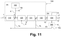
- hydrogen can be separated from the exhaust gas using membrane or pressure swing adsorption, as also described in Figure 11 with Block 180.
- This is also in combination with Hisorp ® CC in the exhaust gas (see Figure 10 ) is advantageous because the exhaust gas is already under pressure.
- the offgas stream can be used in a solid oxide fuel cell (SOFC) to generate electricity.
- SOFC solid oxide fuel cell
- the offgas can be exported.
- the offgas or the remaining offgas can be fed to a fired facility for waste heat utilization (e.g. for preheating the reaction feed, steam generation).
- Additional steam can be used to drive the reboiler of the desorber column in the amine scrubbing process or to generate electricity with a steam turbine or exported.
- a large amount of excess steam is generated.
- the process waste heat can be incorporated, e.g. by a gas-fired reformer.
Landscapes
- Chemical & Material Sciences (AREA)
- Organic Chemistry (AREA)
- Chemical Kinetics & Catalysis (AREA)
- Engineering & Computer Science (AREA)
- Combustion & Propulsion (AREA)
- Inorganic Chemistry (AREA)
- Health & Medical Sciences (AREA)
- General Health & Medical Sciences (AREA)
- Hydrogen, Water And Hydrids (AREA)
Priority Applications (1)
| Application Number | Priority Date | Filing Date | Title |
|---|---|---|---|
| EP23020365.5A EP4501842A1 (fr) | 2023-08-02 | 2023-08-02 | Procédé et installation de production d'hydrogène |
Applications Claiming Priority (1)
| Application Number | Priority Date | Filing Date | Title |
|---|---|---|---|
| EP23020365.5A EP4501842A1 (fr) | 2023-08-02 | 2023-08-02 | Procédé et installation de production d'hydrogène |
Publications (1)
| Publication Number | Publication Date |
|---|---|
| EP4501842A1 true EP4501842A1 (fr) | 2025-02-05 |
Family
ID=87556374
Family Applications (1)
| Application Number | Title | Priority Date | Filing Date |
|---|---|---|---|
| EP23020365.5A Withdrawn EP4501842A1 (fr) | 2023-08-02 | 2023-08-02 | Procédé et installation de production d'hydrogène |
Country Status (1)
| Country | Link |
|---|---|
| EP (1) | EP4501842A1 (fr) |
Citations (3)
| Publication number | Priority date | Publication date | Assignee | Title |
|---|---|---|---|---|
| WO2019110268A1 (fr) * | 2017-12-08 | 2019-06-13 | Haldor Topsøe A/S | Installation et procédé de production de gaz de synthèse |
| WO2020174056A1 (fr) * | 2019-02-28 | 2020-09-03 | Haldor Topsøe A/S | Installation chimique dotée d'une section de reformage et procédé de production d'un produit chimique |
| WO2021110757A1 (fr) * | 2019-12-04 | 2021-06-10 | Haldor Topsøe A/S | Conversion de biogaz en gaz de synthèse pour la production d'hydrocarbures |
-
2023
- 2023-08-02 EP EP23020365.5A patent/EP4501842A1/fr not_active Withdrawn
Patent Citations (3)
| Publication number | Priority date | Publication date | Assignee | Title |
|---|---|---|---|---|
| WO2019110268A1 (fr) * | 2017-12-08 | 2019-06-13 | Haldor Topsøe A/S | Installation et procédé de production de gaz de synthèse |
| WO2020174056A1 (fr) * | 2019-02-28 | 2020-09-03 | Haldor Topsøe A/S | Installation chimique dotée d'une section de reformage et procédé de production d'un produit chimique |
| WO2021110757A1 (fr) * | 2019-12-04 | 2021-06-10 | Haldor Topsøe A/S | Conversion de biogaz en gaz de synthèse pour la production d'hydrocarbures |
Similar Documents
| Publication | Publication Date | Title |
|---|---|---|
| DE69715661T2 (de) | Verfahren und anlage zur herstellung von methanol | |
| DE60304064T2 (de) | Herstellung von kohlenwasserstoffen | |
| EP4249429A1 (fr) | Procédé et installation de fabrication d'un produit cible comprenant le vaporeformage | |
| EP4298187A1 (fr) | Système et procédé de production de combustibles synthétiques sans émission de dioxyde de carbone | |
| EP4031640A1 (fr) | Système et procédé de production de combustibles synthétiques sans eau douce | |
| EP2758338B1 (fr) | Procédé de fabrication de gaz de synthèse | |
| DE102019007672A1 (de) | Verfahren und Anlage zur Herstellung von Monoethylenglycol | |
| EP2598618B1 (fr) | Procédé de production de gaz naturel de substitution | |
| EP4197967A1 (fr) | Procédé et installation de production de méthanol et de monoxyde de carbone | |
| EP4392361B1 (fr) | Synthèse d'ammoniac avec de l'hydrogène neutre de co2 | |
| EP3075706A1 (fr) | Procede et installation destinee a produire un gaz synthetique | |
| EP4357439A1 (fr) | Procédé de fabrication d'un produit cible et installation correspondante | |
| EP4334242B1 (fr) | Procédé de synthèse d'ammoniac et installation de production d'ammoniac | |
| EP3770140B1 (fr) | Procédé et installation de synthèse de méthanol | |
| BE1029714B1 (de) | Ammoniaksynthese mit CO2-neutralem Wasserstoff | |
| LU103225B1 (de) | Grüner Wasserstoff, Synthesegas und Rauchgas mit vermindertem Stickstoffgehalt zur Synthese von Ammoniak und Harnstoff | |
| EP4357440A1 (fr) | Procédé de fabrication d'un produit cible et installation correspondante | |
| DE102014202803A1 (de) | Verfahren zur Herstellung flüssiger und/oder fester Kohlenwasserstoffverbindungen | |
| EP4686697A1 (fr) | Procédé et installation de fabrication d'un produit de procédé ainsi que procédé de fabrication d'une telle installation | |
| DE3345027A1 (de) | Verfahren zur aufbereitung von synthesegasen | |
| EP4691987A1 (fr) | Procédé et installation de fabrication d'un produit de processus | |
| EP3774643B1 (fr) | Élément d'un système à ammoniac et système à ammoniac contenant cet élément et procédé destiné à démarrer le terminal d'un système à ammoniac | |
| EP4574749A1 (fr) | Procédé et installation de production d'un produit à base d'hydrogène | |
| DE102023135125A1 (de) | Grüner Wasserstoff, Synthesegas und Rauchgas mit vermindertem Stickstoffgehalt zur Synthese von Ammoniak und Harnstoff | |
| EP4700005A1 (fr) | Procédé et installation de production de méthanol |
Legal Events
| Date | Code | Title | Description |
|---|---|---|---|
| PUAI | Public reference made under article 153(3) epc to a published international application that has entered the european phase |
Free format text: ORIGINAL CODE: 0009012 |
|
| STAA | Information on the status of an ep patent application or granted ep patent |
Free format text: STATUS: THE APPLICATION HAS BEEN PUBLISHED |
|
| AK | Designated contracting states |
Kind code of ref document: A1 Designated state(s): AL AT BE BG CH CY CZ DE DK EE ES FI FR GB GR HR HU IE IS IT LI LT LU LV MC ME MK MT NL NO PL PT RO RS SE SI SK SM TR |
|
| STAA | Information on the status of an ep patent application or granted ep patent |
Free format text: STATUS: THE APPLICATION IS DEEMED TO BE WITHDRAWN |
|
| 18D | Application deemed to be withdrawn |
Effective date: 20250806 |