EP4502112A1 - Procédé intégré de pyrolyse et de gazéification de résidus et de leurs dérivés et équipement pour sa mise en oeuvre - Google Patents
Procédé intégré de pyrolyse et de gazéification de résidus et de leurs dérivés et équipement pour sa mise en oeuvre Download PDFInfo
- Publication number
- EP4502112A1 EP4502112A1 EP23772753.2A EP23772753A EP4502112A1 EP 4502112 A1 EP4502112 A1 EP 4502112A1 EP 23772753 A EP23772753 A EP 23772753A EP 4502112 A1 EP4502112 A1 EP 4502112A1
- Authority
- EP
- European Patent Office
- Prior art keywords
- waste
- gases
- gasification
- derivatives
- gasifier
- Prior art date
- Legal status (The legal status is an assumption and is not a legal conclusion. Google has not performed a legal analysis and makes no representation as to the accuracy of the status listed.)
- Pending
Links
Images


Classifications
-
- C—CHEMISTRY; METALLURGY
- C10—PETROLEUM, GAS OR COKE INDUSTRIES; TECHNICAL GASES CONTAINING CARBON MONOXIDE; FUELS; LUBRICANTS; PEAT
- C10B—DESTRUCTIVE DISTILLATION OF CARBONACEOUS MATERIALS FOR PRODUCTION OF GAS, COKE, TAR, OR SIMILAR MATERIALS
- C10B47/00—Destructive distillation of solid carbonaceous materials with indirect heating, e.g. by external combustion
- C10B47/28—Other processes
- C10B47/30—Other processes in rotary ovens or retorts
-
- C—CHEMISTRY; METALLURGY
- C10—PETROLEUM, GAS OR COKE INDUSTRIES; TECHNICAL GASES CONTAINING CARBON MONOXIDE; FUELS; LUBRICANTS; PEAT
- C10B—DESTRUCTIVE DISTILLATION OF CARBONACEOUS MATERIALS FOR PRODUCTION OF GAS, COKE, TAR, OR SIMILAR MATERIALS
- C10B53/00—Destructive distillation, specially adapted for particular solid raw materials or solid raw materials in special form
- C10B53/07—Destructive distillation, specially adapted for particular solid raw materials or solid raw materials in special form of solid raw materials consisting of synthetic polymeric materials, e.g. tyres
-
- C—CHEMISTRY; METALLURGY
- C10—PETROLEUM, GAS OR COKE INDUSTRIES; TECHNICAL GASES CONTAINING CARBON MONOXIDE; FUELS; LUBRICANTS; PEAT
- C10J—PRODUCTION OF PRODUCER GAS, WATER-GAS, SYNTHESIS GAS FROM SOLID CARBONACEOUS MATERIAL, OR MIXTURES CONTAINING THESE GASES; CARBURETTING AIR OR OTHER GASES
- C10J3/00—Production of combustible gases containing carbon monoxide from solid carbonaceous fuels
- C10J3/58—Production of combustible gases containing carbon monoxide from solid carbonaceous fuels combined with pre-distillation of the fuel
- C10J3/60—Processes
-
- C—CHEMISTRY; METALLURGY
- C10—PETROLEUM, GAS OR COKE INDUSTRIES; TECHNICAL GASES CONTAINING CARBON MONOXIDE; FUELS; LUBRICANTS; PEAT
- C10B—DESTRUCTIVE DISTILLATION OF CARBONACEOUS MATERIALS FOR PRODUCTION OF GAS, COKE, TAR, OR SIMILAR MATERIALS
- C10B1/00—Retorts
- C10B1/10—Rotary retorts
-
- C—CHEMISTRY; METALLURGY
- C10—PETROLEUM, GAS OR COKE INDUSTRIES; TECHNICAL GASES CONTAINING CARBON MONOXIDE; FUELS; LUBRICANTS; PEAT
- C10B—DESTRUCTIVE DISTILLATION OF CARBONACEOUS MATERIALS FOR PRODUCTION OF GAS, COKE, TAR, OR SIMILAR MATERIALS
- C10B31/00—Charging devices
- C10B31/02—Charging devices for charging vertically
- C10B31/04—Charging devices for charging vertically coke ovens with horizontal chambers
-
- C—CHEMISTRY; METALLURGY
- C10—PETROLEUM, GAS OR COKE INDUSTRIES; TECHNICAL GASES CONTAINING CARBON MONOXIDE; FUELS; LUBRICANTS; PEAT
- C10B—DESTRUCTIVE DISTILLATION OF CARBONACEOUS MATERIALS FOR PRODUCTION OF GAS, COKE, TAR, OR SIMILAR MATERIALS
- C10B49/00—Destructive distillation of solid carbonaceous materials by direct heating with heat-carrying agents including the partial combustion of the solid material to be treated
- C10B49/02—Destructive distillation of solid carbonaceous materials by direct heating with heat-carrying agents including the partial combustion of the solid material to be treated with hot gases or vapours, e.g. hot gases obtained by partial combustion of the charge
- C10B49/04—Destructive distillation of solid carbonaceous materials by direct heating with heat-carrying agents including the partial combustion of the solid material to be treated with hot gases or vapours, e.g. hot gases obtained by partial combustion of the charge while moving the solid material to be treated
-
- C—CHEMISTRY; METALLURGY
- C10—PETROLEUM, GAS OR COKE INDUSTRIES; TECHNICAL GASES CONTAINING CARBON MONOXIDE; FUELS; LUBRICANTS; PEAT
- C10B—DESTRUCTIVE DISTILLATION OF CARBONACEOUS MATERIALS FOR PRODUCTION OF GAS, COKE, TAR, OR SIMILAR MATERIALS
- C10B51/00—Destructive distillation of solid carbonaceous materials by combined direct and indirect heating
-
- C—CHEMISTRY; METALLURGY
- C10—PETROLEUM, GAS OR COKE INDUSTRIES; TECHNICAL GASES CONTAINING CARBON MONOXIDE; FUELS; LUBRICANTS; PEAT
- C10B—DESTRUCTIVE DISTILLATION OF CARBONACEOUS MATERIALS FOR PRODUCTION OF GAS, COKE, TAR, OR SIMILAR MATERIALS
- C10B53/00—Destructive distillation, specially adapted for particular solid raw materials or solid raw materials in special form
-
- C—CHEMISTRY; METALLURGY
- C10—PETROLEUM, GAS OR COKE INDUSTRIES; TECHNICAL GASES CONTAINING CARBON MONOXIDE; FUELS; LUBRICANTS; PEAT
- C10B—DESTRUCTIVE DISTILLATION OF CARBONACEOUS MATERIALS FOR PRODUCTION OF GAS, COKE, TAR, OR SIMILAR MATERIALS
- C10B57/00—Other carbonising or coking processes; Features of destructive distillation processes in general
- C10B57/02—Multi-step carbonising or coking processes
-
- C—CHEMISTRY; METALLURGY
- C10—PETROLEUM, GAS OR COKE INDUSTRIES; TECHNICAL GASES CONTAINING CARBON MONOXIDE; FUELS; LUBRICANTS; PEAT
- C10B—DESTRUCTIVE DISTILLATION OF CARBONACEOUS MATERIALS FOR PRODUCTION OF GAS, COKE, TAR, OR SIMILAR MATERIALS
- C10B57/00—Other carbonising or coking processes; Features of destructive distillation processes in general
- C10B57/16—Features of high-temperature carbonising processes
-
- C—CHEMISTRY; METALLURGY
- C10—PETROLEUM, GAS OR COKE INDUSTRIES; TECHNICAL GASES CONTAINING CARBON MONOXIDE; FUELS; LUBRICANTS; PEAT
- C10J—PRODUCTION OF PRODUCER GAS, WATER-GAS, SYNTHESIS GAS FROM SOLID CARBONACEOUS MATERIAL, OR MIXTURES CONTAINING THESE GASES; CARBURETTING AIR OR OTHER GASES
- C10J3/00—Production of combustible gases containing carbon monoxide from solid carbonaceous fuels
- C10J3/02—Fixed-bed gasification of lump fuel
- C10J3/20—Apparatus; Plants
- C10J3/34—Grates; Mechanical ash-removing devices
- C10J3/40—Movable grates
-
- F—MECHANICAL ENGINEERING; LIGHTING; HEATING; WEAPONS; BLASTING
- F23—COMBUSTION APPARATUS; COMBUSTION PROCESSES
- F23G—CREMATION FURNACES; CONSUMING WASTE PRODUCTS BY COMBUSTION
- F23G5/00—Incineration of waste; Incinerator constructions; Details, accessories or control therefor
- F23G5/002—Incineration of waste; Incinerator constructions; Details, accessories or control therefor characterised by their grates
-
- F—MECHANICAL ENGINEERING; LIGHTING; HEATING; WEAPONS; BLASTING
- F23—COMBUSTION APPARATUS; COMBUSTION PROCESSES
- F23G—CREMATION FURNACES; CONSUMING WASTE PRODUCTS BY COMBUSTION
- F23G5/00—Incineration of waste; Incinerator constructions; Details, accessories or control therefor
- F23G5/02—Incineration of waste; Incinerator constructions; Details, accessories or control therefor with pretreatment
- F23G5/027—Incineration of waste; Incinerator constructions; Details, accessories or control therefor with pretreatment pyrolising or gasifying stage
-
- F—MECHANICAL ENGINEERING; LIGHTING; HEATING; WEAPONS; BLASTING
- F23—COMBUSTION APPARATUS; COMBUSTION PROCESSES
- F23G—CREMATION FURNACES; CONSUMING WASTE PRODUCTS BY COMBUSTION
- F23G5/00—Incineration of waste; Incinerator constructions; Details, accessories or control therefor
- F23G5/20—Incineration of waste; Incinerator constructions; Details, accessories or control therefor having rotating or oscillating drums
-
- C—CHEMISTRY; METALLURGY
- C10—PETROLEUM, GAS OR COKE INDUSTRIES; TECHNICAL GASES CONTAINING CARBON MONOXIDE; FUELS; LUBRICANTS; PEAT
- C10J—PRODUCTION OF PRODUCER GAS, WATER-GAS, SYNTHESIS GAS FROM SOLID CARBONACEOUS MATERIAL, OR MIXTURES CONTAINING THESE GASES; CARBURETTING AIR OR OTHER GASES
- C10J2300/00—Details of gasification processes
- C10J2300/09—Details of the feed, e.g. feeding of spent catalyst, inert gas or halogens
- C10J2300/0913—Carbonaceous raw material
- C10J2300/0946—Waste, e.g. MSW, tires, glass, tar sand, peat, paper, lignite, oil shale
-
- C—CHEMISTRY; METALLURGY
- C10—PETROLEUM, GAS OR COKE INDUSTRIES; TECHNICAL GASES CONTAINING CARBON MONOXIDE; FUELS; LUBRICANTS; PEAT
- C10J—PRODUCTION OF PRODUCER GAS, WATER-GAS, SYNTHESIS GAS FROM SOLID CARBONACEOUS MATERIAL, OR MIXTURES CONTAINING THESE GASES; CARBURETTING AIR OR OTHER GASES
- C10J2300/00—Details of gasification processes
- C10J2300/09—Details of the feed, e.g. feeding of spent catalyst, inert gas or halogens
- C10J2300/0953—Gasifying agents
- C10J2300/0956—Air or oxygen enriched air
-
- C—CHEMISTRY; METALLURGY
- C10—PETROLEUM, GAS OR COKE INDUSTRIES; TECHNICAL GASES CONTAINING CARBON MONOXIDE; FUELS; LUBRICANTS; PEAT
- C10J—PRODUCTION OF PRODUCER GAS, WATER-GAS, SYNTHESIS GAS FROM SOLID CARBONACEOUS MATERIAL, OR MIXTURES CONTAINING THESE GASES; CARBURETTING AIR OR OTHER GASES
- C10J2300/00—Details of gasification processes
- C10J2300/16—Integration of gasification processes with another plant or parts within the plant
- C10J2300/1603—Integration of gasification processes with another plant or parts within the plant with gas treatment
- C10J2300/1606—Combustion processes
-
- C—CHEMISTRY; METALLURGY
- C10—PETROLEUM, GAS OR COKE INDUSTRIES; TECHNICAL GASES CONTAINING CARBON MONOXIDE; FUELS; LUBRICANTS; PEAT
- C10J—PRODUCTION OF PRODUCER GAS, WATER-GAS, SYNTHESIS GAS FROM SOLID CARBONACEOUS MATERIAL, OR MIXTURES CONTAINING THESE GASES; CARBURETTING AIR OR OTHER GASES
- C10J2300/00—Details of gasification processes
- C10J2300/18—Details of the gasification process, e.g. loops, autothermal operation
- C10J2300/1846—Partial oxidation, i.e. injection of air or oxygen only
-
- F—MECHANICAL ENGINEERING; LIGHTING; HEATING; WEAPONS; BLASTING
- F23—COMBUSTION APPARATUS; COMBUSTION PROCESSES
- F23G—CREMATION FURNACES; CONSUMING WASTE PRODUCTS BY COMBUSTION
- F23G2201/00—Pretreatment
- F23G2201/30—Pyrolysing
-
- F—MECHANICAL ENGINEERING; LIGHTING; HEATING; WEAPONS; BLASTING
- F23—COMBUSTION APPARATUS; COMBUSTION PROCESSES
- F23G—CREMATION FURNACES; CONSUMING WASTE PRODUCTS BY COMBUSTION
- F23G2201/00—Pretreatment
- F23G2201/40—Gasification
-
- F—MECHANICAL ENGINEERING; LIGHTING; HEATING; WEAPONS; BLASTING
- F23—COMBUSTION APPARATUS; COMBUSTION PROCESSES
- F23G—CREMATION FURNACES; CONSUMING WASTE PRODUCTS BY COMBUSTION
- F23G2203/00—Furnace arrangements
- F23G2203/101—Furnace arrangements with stepped or inclined grate
-
- F—MECHANICAL ENGINEERING; LIGHTING; HEATING; WEAPONS; BLASTING
- F23—COMBUSTION APPARATUS; COMBUSTION PROCESSES
- F23G—CREMATION FURNACES; CONSUMING WASTE PRODUCTS BY COMBUSTION
- F23G2203/00—Furnace arrangements
- F23G2203/20—Rotary drum furnace
Definitions
- solid waste is defined as: waste in solid and semi-solid states, which results from activities of industrial, domestic, hospital, commercial, agricultural, service and sweeping origin.
- This definition includes sludge from water treatment systems, those generated in pollution control equipment and installations, as well as certain liquids whose particularities make their release into the public sewage system or water bodies unfeasible, or require solutions that are technically and economically unfeasible in the face of the best available technology.
- energy recovery or energy use is defined as: "process of using thermal energy generated from the thermal oxidation of waste intended for combustion, gasification and/or pyrolysis processes, which fundamentally uses thermal energy for industrial or electricity generation purposes, carried out under controlled conditions and with due environmental control and monitoring".
- the macro operations of the process defined in the present invention are called: drying and pyrolysis, gasification and, finally, the combustion of gases derived from the previous processes.
- Drying is the endothermic process of removing water from waste and its derivatives, using in this process the heat resulting from the exothermic reactions of gasification processes.
- Pyrolysis is an endothermic process, which requires an external source of heat. It consists of the thermal degradation of waste in the partial or total absence of an oxidizing agent (oxygen) and with process temperatures that vary, from 400°C, until the beginning of the gasification regime. Pyrolysis is used to transform polymers, or materials containing polymers, into products that at CNTP (Standard conditions for temperature and pressure) are liquid (condensable), gaseous (non-condensable) or solid (predominantly coal).
- Gasification can be defined as partial oxidation of solid or semisolid carbonaceous material (biomass/wood, waste, coal, etc.), into a combustible gas (synthesis gas, mainly H 2 , CO, N 2 , CO 2 ), occurring at elevated temperature, that is, between 500°C and 1,400°C, and at pressures varying between atmospheric and 33 bar.
- synthesis gas mainly H 2 , CO, N 2 , CO 2
- Combustion is characterized by the combustion or oxidation zone established by the entry of oxygen into a reactor.
- Oxygen reacts with the products of pyrolysis and gasification, releasing thermal energy (exothermic reaction), which provides heat to the other stages of the process and produces mainly CO 2 , H 2 O and N 2 .
- the heat produced in the overall process covering the three operations can be used in industrial facilities, producing thermal energy for the most varied applications, such as drying or evaporation of various materials, drying of sludge, production of process steam or production of electricity in Rankine cycle.
- Incineration is one of the most frequent forms of thermal processing of waste and its derivatives that can be applied to a wide variety of types of materials. It occurs when there is a surplus of oxygen for complete oxidation. During the incineration of solid Municipal waste it is possible to reduce up to 90% of the volume and 75% of the initial weight of the waste.
- Incineration consists of a high-temperature thermal oxidation process, typically ranging between 800°C and 1,300°C. Facilities require additional air pollution control equipment and the energy released by combustion of waste may or may not be reused.
- an incinerator The performance of an incinerator is related to several factors, including variation in the composition of the waste to be incinerated, temperature, residence time of gases in the secondary chamber and swirling or excess air. Therefore, the operation of an incinerator is based on the tripod of temperature x retention time x quantity of air, necessary for the complete burning of waste, resulting in satisfactory performance of the equipment with a large reduction in the emission of polluting gases.
- the state of the art presents pyrolysis processes, gasification processes and waste incineration processes and their derivatives in different equipment, that is, processes or equipment dedicated to pyrolysis to obtain their by-products, processes or equipment dedicated to gasification to obtain their by-products and processes or equipment dedicated to incineration to obtain their by-products.
- incinerators seek to achieve complete combustion by employing temperatures in the range of 540 to 1,090°C, to capture the heat generated, and to manage emissions through pollution controls.
- MSW Mossunicipal Solid Waste
- PCDD Polychlorinated dibenzo-p-dioxins
- PCDF Polychlorinated dibenzofurans
- MSW Municipal Solid Waste
- the individual grates that move the materials to be heat treated during the endothermic and exothermic processes have the same configuration throughout the entire length of this single chamber, with the following description in paragraph 53 "The holes (1.7.1.5 - Figure 5 and 6 ) in the protruding region have the function of giving uniform passage to the fluid or air coming from the air/fume mixture equalization chambers under the grate sets, which also have the function of collecting fines that eventually pass through the grates".
- this gasifier model does not allow the processing of materials containing fines, such as sludge from an effluent treatment plant, polymeric materials in powder form from drying systems or industrial processes, powdered coal or pulverized coal, as well as materials in the liquid phase such as contaminated oils, contaminated solvents among a multitude of other possibilities. Which makes this model limited to solid-state materials with particle sizes larger than the holes in your grate.
- this type of cast iron grate described in paragraph 49 of PI 1000573-0 B1 once heated, it ends up expanding due to thermal expansion, causing cracks in the fittings. Also, over time of use, the natural wear of these materials due to abrasion caused by movement between the fixed part and the moving part, leads to even larger gaps, which for solid waste should not present problems, but the range of fine materials, pastes or liquids, cannot be processed, leaving the equipment even more limited.
- the conveyor belt (1.1) raises the MSW to the intake, which is done by means of a drawer (1.2.1 - Figure 1 ) with a powerful hydraulic drive (1.2.1.1 - Figure 1 ).
- the intake duct (1.3.1 Figure 1 ) is designed to always remain full of material compacted by the drawer, preventing the entry of air and the exit of gases into the atmosphere.
- This catalyst set is necessary for this process C1 1000573-0, due to the fact that this requires an increase in the calorific value of the gas generated.
- this catalyst set will be dispensed with and will not be part of the required process, because this new model allows for better conditions for endothermic reactions, producing a gas with better calorific value compared to conventional gasifiers.
- the pyrolysis process is still at the state of the art.
- products with added values are generated, such as oil, gases and coal that can be used as a source of fuel or in other uses related to industry.
- the carbonization pyrolysis process (slow pyrolysis) is aimed specifically at the production of coal
- fast pyrolysis is considered an advanced process, in which, by controlling the process parameters, considerable quantities of oil can be obtained.
- it is an endothermic process, it requires quantities of heat proportional to the masses of waste and their derivatives to be consumed for their decomposition.
- the addition of heat is commonly done indirectly, that is, the heat conductor, whether by steam, thermal oil or even gases, which do not come into contact with the material to be processed.
- the invention "INTEGRATED PYROLYSIS AND GASIFICATION PROCESS OF WASTE AND ITS DERIVATIVES AND THE EQUIPMENT TO CARRY IT OUT" was developed to solve the problem of treating fine, powdery, pasty, sludge and liquid waste, which can be treated individually or in blends with other waste such as Municipal, commercial or industrial solid waste. Such residues with reduced particle size cannot be processed in conventional grate gasification processes.
- the present invention also offers an integral destination for waste processed by the pyrolysis technique, which generates coals that end up having no application or use when derived from waste containing heavy metals or other organic molecules.
- the present invention proposes to solve both problems by integrating two distinct processes for comprehensive treatment, being able to meet a demand for waste that today basically only finds disposal in landfills and also greatly reduce the solid by-products of pyrolytic processes for waste treatment.
- the invention "INTEGRATED PYROLYSIS AND GASIFICATION PROCESS OF WASTE AND ITS DERIVATIVES AND THE EQUIPMENT TO CARRY IT OUT" aims to make waste treatment with energy recovery available to the market, through an integrated process, in an integrated equipment, with the capacity to meet waste demands which are currently sent to landfills without being used.
- waste generators with a process that includes waste with characteristics that do not conform to conventional processes with additional energy use, and that fully complies with environmental laws and standards.
- the novelty of the invention "INTEGRATED PYROLYSIS AND GASIFICATION PROCESS OF WASTE AND ITS DERIVATIVES AND THE EQUIPMENT TO CARRY IT OUT", comprises the integration of two distinct processes that enables the optimization of the pyrolysis technique, increasing its efficiency in terms of mass effectiveness of treated waste and also increasing the range of waste that can be treated using the grate gasification technique, offering:
- the EQUIPMENT of the present invention presents its functional technical composition comprising 04 basic parts: material feeding and dosing and gas removal set (1.1), rotary pyrolysis set (1.2), gasification set (1.3) and combustion set of generated gases (1.4).
- the material feeder and doser and gas removal set (1.1) comprises:
- the rotary pyrolysis kiln set (1.2) comprises:
- the gasification set (1.3) comprises:
- the combustion set of gases generated (1.4) comprises:
- the present invention called "INTEGRATED PYROLYSIS AND GASIFICATION PROCESS OF WASTE AND ITS DERIVATIVES AND THE EQUIPMENT TO CARRY IT OUT", integrates the processes of pyrolysis in a rotary kiln (1.2) and gasification on moving grates in the gasifier (1.3).
- the equipment components(1) are built with materials suitable for each phase of the overall process, according to temperature, humidity, electrochemical corrosivity and abrasiveness.
- control is carried out over the gas exhaust fan (1.4.11).
- the basic instrumentation seen in Figure 6 , comprises:
- Such sensors will be controlled by a control loop that will control the frequency inverters of the fans and exhaust fans (1.4.1), (1.4.11), (1.3.9) and (1.4.6), the frequency inverter of the gearmotor (1.2.2) that drives the rotation of the kiln (1.2.1), valves (1.1.3), (1.1.5.3), (1.1.5.5), (1.3.5), (1.3.10) and (1.4.7), and the movement of the moving grates (1.3.1.2) by the hydraulic unit (1.3.3) managing the entire operation of the equipment (1).
- the feeder (1.1.1) In the material feeder and doser and gas removal set (1.1) the feeder (1.1.1); It can be of different types, such as the belt represented in the figures, or claws, or mugs, among others.
- the upper hopper (1.1.2) acts as a funnel receiving the material to be processed, which then meets the valve (1.1.3) to control the material input volume.
- the lower hopper (1.1.4) directs the dosed material to the feeder inlet of the rotary pyrolysis kiln (1.1.5).
- the feeder of the rotary pyrolysis kiln has the body (1.1.5.1) of several functions, which are to offer the material to be processed the path to the set (1.2) or through the hopper (1.1.5.1.1), and the path of counterflow gases to the outlet (1.1.5.4) through the valve (1.1.5.5).
- Attached to the body (1.1.) is also the safety valve (1.1.5.2), which directs, in cases of emergencies/abrupt stops, the gases to the chimney (1.1.5.3).
- the feeder/rotary kiln seal (1.1.5.6) in the region of separation between the moving part of the kiln (1.2.1) and the fixed part of the body (1.1.5.1) prevents false air from entering the system.
- the rotary kiln set (1.2) performs the function of pyrolysis of the material in process, which, for this purpose, has its body (1.2.1.1) rotated, by the gear motor (1.2.2), on the tracks (1.2.1.2).
- the dosing feeder (1.1) feeds the rotary kiln (1.2) for the pyrolysis reactions, where the seal (1.1.5.6) of the feeder/doserset (1.1) and the sealing (1.3.11) of the gasifier set (1.3) guarantee the absence of false air passage and gas leakage between moving parts of the rotary kiln (1.2) and those fixed on both sides of it.
- the gear motor (1.2.2) determines the rotation speed of the rotary kiln (1.2.1) which provides the revolving and movement of the material so that good pyrolysis occurs and the material is sent to the gasifier set (1.3).
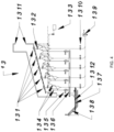
- the gasification set (1.3) comprises sets of grate sections (1.3.1), where, in the direction of material flow, the odd lines are with fixed grates (1.3.1.1) and the even lines are with moving grates (1.3.1.2).
- the number of grates lines (1.3.1.1) and (1.3.1.2) for each independent section (1.3.1), as well as the number of grates per even or odd line, depends on the processing capacity or size of each equipment.
- the movement of the grate sets(1.3.1.2) is done by hydraulic actuators(1.3.2), these can be cylinders or hydraulic motors, where propulsion is offered by the hydraulic unit with pump and reservoir(1.3.3).
- the moving grates (1.3.1.2) move with the upper sliding-fitting flaps (1.3.1.1.4) sliding over the adjacent lower sliding-fitting flaps (1.3.1.1.3), providing the necessary sealing.
- ash collectors (1.3.4) residual from the process, which, like hoppers, direct such ash to the ash collection valves (1.3.5), ash conveyor screw (1.3.6), and finally, using a Redler-type conveyor (1.3.8), out of the equipment (1).
- the Redler type conveyor (1.3.8) has its lower part covered by a water seal (1.3.7) preventing false air from entering the equipment (1).
- the air blown into the gasifier (1.3) is controlled by a frequency inverter that operates the blower (1.3.9) and drives the blown air damper valves (1.3.10).
- the gasifier/rotary kiln seal (1.3.11) prevents false air from entering.
- the level sensor/switch (1.3.12) maintains the seal level at such a height that it does not allow false air to enter through the gasifier Redler (1.3.8) (1.3).
- each grate section (1.3.1) there is a pressure sensor (1.5.1), also providing data for equipment automation (1). Based on the signals from these sensors, the blown air damper valves (1.3.10) are opened, the purpose of which is to maintain constant pressure at these points.
- the gas removal duct (1.1.5.4), best seen in Figure 2 , will be arranged next to the material inlet in the rotary kiln (1.2.1), so that the flow of gases is countercurrent in relation to solid, pasty and liquid material.
- Controlling the rotation speed of the kiln (1.2.1) and controlling the amount of material to be processed must maintain the temperature of the mixture of gasification gases from set (1.3) plus pyrolytic gases from set (1.2) at an average value 400°C (between 300 and 500°C), to avoid condensation of pyrolytic gases.
- the O 2 measuring cell by lambda probe (1.5.3) interconnected to the operating system, allows control and guarantees that there will be no oxygen available for complete combustion in the pyrolysis chamber (1.2).
- the internal working temperature of the rotary kiln (1.2.1) for pyrolysis reactions should be around 400°C on average, in the gasifier (1.3) the average internal working temperature will be around 650°C.
- blower air insufflation(1.3.9) which is controlled by the temperature, pressure and oxygen concentration given by the sensors(1.5) above each grate section(1.3.1) and by the pressure(1.5.1) below each section(1.3.1) of grate.
- the control of the gas flow in the gasifier and in the rotary kiln will be done by the air blower frequency inverter (1.4.1) coupled to the duct so that the Venturi effect is created in the Venturi (1.4.3).
- the control will be done by the pressure above the grates (1.3.1) of the gasification chamber, which must be below atmospheric pressure to guarantee a vacuum process.
- the Venturi effect guarantees the flow of gases and pressure throughout the process, as well as providing the torsional combustor(1.4) with a mixture of combustible gases from the pyrolysis and gasification processes plus the oxidizing atmospheric air from the blower (1.4.6).
- the blower (1.4.6) is controlled by the valve (1.4.7) together with a frequency inverter.
- ash contain the inorganic fraction present in the waste and its derivatives.
- the composition of the ash and its quantity will depend on the type of waste to be processed and must be characterized/classified and disposed of appropriately.
- the gasifier (1.3) has the function of conditioning the material from the rotary kiln (1.2) for substoichiometric reactions to produce gas operating at average temperatures of 650°C, and, for this purpose, it is coated with ceramic material to maintain conditions at these temperatures and not be attacked by corrosive gases.
- the fixed (1.3.1.1) and moving (1.3.1.2) grates of the gasifier (1.3) are made of cast iron with special alloys and have the function of pushing the materials.
- the odd rows of grates are fixed (1.3.1.1) and the even rows are moving (1.3.1.2) with forward and backward movement in the direction of material flow.
- the individual grates that move the materials to be heat treated during the exothermic processes have on their upper face a recess (1.3.1.1.1) in the form of a descending ramp, outside the travel area, that is, outside the contact area between the moving and fixed grate during the movement of the grate set.
- This recess allows transverse holes (1.3.1.1.2) to be made in the direction of passage of materials, reducing the possibility of passage of fine materials to the bottom of the gasifier (1.3) and/or obstruction of the holes, and also benefiting the control of the air flow given by the blower (1.3.9) for the oxidation reactions on the grate.
- the individual grates have flaps and recesses on the side edges of the male (1.3.1.1.3) and female (1.3.1.1.4) type, in order to prevent the passage of fine materials through the gaps and also do not allow air flow.
- each section (1.3.1) of grates can be activated individually, according to the responses to the sets of sensors (1.5.) located on each set of grates.
- the movement of the moving grates (1.3.1.2) of each section can be varied in terms of the speed of advancement and retreat as well as the time between movement activations.
- the ash collectors (1.3.4) of the gasifier (1.3) have the purpose of removing ash, directing it to valves (1.3.5) that control the ash output flow.
- valves (1.3.5) When the valves (1.3.5) are opened, the ash falls onto a collector (1.3.6) with a screw conveyor, which directs it to the entrance of a Redler-type conveyor (1.3.8) submerged by a water seal with a level (1.3.7).
- the blower (1.3.9) is located below the grate (1.3.1), and ensures the appropriate amount of air in each section of the grate through the damper valves (1.3.10), in order to maintain controlled substoichiometric reactions in each section of the gasifier (1.3).
- the gas removal duct (1.1.5.4) carries gases from the pyrolysis and gasification processes towards the combustion set (1.4).
- the air blower (1.4.1) is controlled by a frequency inverter.
- the air from the blower (1.4.1) goes to a Venturi (1.4.3) that drags the gases from the duct (1.5.5.4) towards the combustion set (1.4).
- the duct closing safety valve (1.1.5.5) acts to close the duct (1.1.5.4) in case of sudden stop/emergency.
- the safety chimney (1.1.5.3) has the purpose of evacuating the pyrolysis and gasification chambers, with the concomitant action of the chimney opening safety valve (1.1.5.2).
- the combustion set (1.4) aims to condition perfect combustion of gases produced in the pyrolysis and gasification processes. It is coated with ceramic material in order to withstand temperature conditions of up to 1,400°C.
- the pilot burner (1.4.5) operates only for initial heating of the chamber (1.4.8) or to act in the event of a flame extinguishing emergency.
- the air blowers (1.4.6) serve to supply the concentration of air necessary for combustion, this concentration being controlled by the valve (1.4.7) and frequency inverters.
- the gases produced (from pyrolysis and gasification) have a tangential entry (1.4.8.1) into the combustion chamber (1.4.8), which has this arrangement so that such gases are directed to the internal walls of the combustor in a torsional movement or swirl and, consequently, increase turbulence to increase burning efficiency.
- the hydraulic control unit (1.3.3) has the purpose of activating the moving grates, a set of registers with pneumatic actuators.
- the valves (1.3.10) have the function of opening and closing the upward air flow in each section of the gasifier.
- the invention "INTEGRATED PYROLYSIS AND GASIFICATION PROCESS OF WASTE AND ITS DERIVATIVES AND THE EQUIPMENT TO CARRY IT OUT" receives waste and its derivatives, carries out the pyrolysis and gasification process sequentially, producing a mixture of gases with combustible contents, which we can now call “Derived Combustible Gases of Waste” (DCGW).
- the combustion chamber (1.4) is sized in terms of diameter and length so that it obtains a minimum retention time of 1.5 seconds for the gases inside the chamber at temperatures between 1,000°C and 1,400°C.
- combustion gases can be used in different ways, the most common being in industrial dryers, in industrial steam production, in Rankine cycle electrical energy production, or others that can be compatible with these characteristics.
- the 1st variant of the process is characterized by the fact that it comprises:
- Figure 6 shows the first variant of the invention "INTEGRATED PYROLYSIS AND GASIFICATION PROCESS OF WASTE AND ITS DERIVATIVES AND THE EQUIPMENT TO CARRY IT OUT", here called equipment(2).
- the exhaust fan (1.4.11) maintains constant pressure in the integrated pyrolysis and gasification processes. In this case, the combustion air injection will be made exclusively at the combustion chamber inlet, by the blower (1.4.6).
- the 2nd variant of the process is characterized by the fact that it comprises:
- the second variant is configured by the equipment(3) not combusting gases directly at the system outlet with Venturi(1.4.3) of the best proposed solution or at the exhaust fan outlet(1.4.11) of the first variant.
- equipment (3) combustible gases derived from waste will be sent to the outlet (1.4.15) by an exhaust fan (1.411) controlled by a frequency inverter.
- CGDW Compbustible Gases Derived from Waste
- the treatment must be in accordance with the uses, such as burning in engines, direct burning in gas turbines, obtaining fuel oils, among others.
- the present invention is from the waste treatment and energy recovery industry sector.
Landscapes
- Chemical & Material Sciences (AREA)
- Engineering & Computer Science (AREA)
- Oil, Petroleum & Natural Gas (AREA)
- Organic Chemistry (AREA)
- Materials Engineering (AREA)
- Combustion & Propulsion (AREA)
- Mechanical Engineering (AREA)
- General Engineering & Computer Science (AREA)
- Chemical Kinetics & Catalysis (AREA)
- General Chemical & Material Sciences (AREA)
- Gasification And Melting Of Waste (AREA)
- Processing Of Solid Wastes (AREA)
- Treatment Of Sludge (AREA)
Applications Claiming Priority (2)
| Application Number | Priority Date | Filing Date | Title |
|---|---|---|---|
| BR102022005707-9A BR102022005707A2 (pt) | 2022-03-25 | 2022-03-25 | Processo integrado de pirólise e gaseificação de resíduos e seus derivados e o equipamento para sua realização |
| PCT/BR2023/050030 WO2023178400A1 (fr) | 2022-03-25 | 2023-01-27 | Procédé intégré de pyrolyse et de gazéification de résidus et de leurs dérivés et équipement pour sa mise en oeuvre |
Publications (2)
| Publication Number | Publication Date |
|---|---|
| EP4502112A1 true EP4502112A1 (fr) | 2025-02-05 |
| EP4502112A4 EP4502112A4 (fr) | 2026-04-15 |
Family
ID=88099407
Family Applications (1)
| Application Number | Title | Priority Date | Filing Date |
|---|---|---|---|
| EP23772753.2A Pending EP4502112A4 (fr) | 2022-03-25 | 2023-01-27 | Procédé intégré de pyrolyse et de gazéification de résidus et de leurs dérivés et équipement pour sa mise en oeuvre |
Country Status (6)
| Country | Link |
|---|---|
| US (1) | US20250066670A1 (fr) |
| EP (1) | EP4502112A4 (fr) |
| KR (1) | KR20240167778A (fr) |
| BR (1) | BR102022005707A2 (fr) |
| CL (1) | CL2023003634A1 (fr) |
| WO (1) | WO2023178400A1 (fr) |
Families Citing this family (1)
| Publication number | Priority date | Publication date | Assignee | Title |
|---|---|---|---|---|
| WO2025260151A1 (fr) * | 2024-06-21 | 2025-12-26 | Integral Wte Ltda | Procédé intégré pour pyrolyse directe, combustion stœchiométrique et post-combustion, et équipement pour sa réalisation |
Family Cites Families (12)
| Publication number | Priority date | Publication date | Assignee | Title |
|---|---|---|---|---|
| DE59309121D1 (de) * | 1992-02-26 | 1998-12-17 | Hans Kuenstler | Verfahren zum einschmelzen von verbrennungsrückständen in schlacke |
| DE4220265C1 (en) * | 1992-06-20 | 1993-05-06 | Deutsche Tiefbohr-Aktiengesellschaft, 4444 Bad Bentheim, De | Prodn. of gasification material in sloping bed reactor |
| GR1001615B (el) * | 1993-06-04 | 1994-07-29 | Viokat Anonymos Techniki & Vio | Μέ?οδος αεριοποίησης στερεών καυσίμων χαμηλού ?ερμικού περιεχομένου με ωφέλιμη αξιοποίηση στην παραγωγή ηλεκτρικής ενέργειας χωρίς δημιουργία ρύπανσης περιβάλλοντος. |
| JP4790412B2 (ja) * | 2005-12-28 | 2011-10-12 | 中外炉工業株式会社 | バイオマスガス化装置 |
| TR200705430A2 (tr) * | 2007-08-03 | 2008-12-22 | Detes Maden Enerji̇ Ve Çevre Teknoloji̇si̇ Si̇stemleri̇ Li̇mi̇ted Şi̇rketi̇ | Katı yakıt gazlaştırma ve gaz temizleme sistemi. |
| UY33038A (es) * | 2009-11-20 | 2011-06-30 | Rv Lizenz Ag | Uso termico y quimico de sustancias cabonaceas en particular para la generacion de energia sin emisiones |
| BRPI1000573F1 (pt) * | 2010-02-10 | 2020-08-11 | Energia Limpa Do Brasil Ind E Comercio De Equipamentos S/A | processo de produção de combustível industrial a partir de resíduos sólidos urbanos |
| CN101906325B (zh) * | 2010-07-20 | 2013-09-04 | 阳光凯迪新能源集团有限公司 | 生物质低温裂解高温气化工艺及其设备 |
| CN101906326B (zh) * | 2010-07-20 | 2013-03-13 | 武汉凯迪控股投资有限公司 | 生物质双炉连体裂解气化工艺及其设备 |
| US9321640B2 (en) * | 2010-10-29 | 2016-04-26 | Plasco Energy Group Inc. | Gasification system with processed feedstock/char conversion and gas reformulation |
| CN102703098B (zh) * | 2012-05-29 | 2013-12-11 | 东南大学 | 生物质制取生物油的装置及其方法 |
| SE542564C2 (en) * | 2017-10-13 | 2020-06-09 | Cortus Ab | Process and apparatus for hydrotreatment of pyrolysis oil |
-
2022
- 2022-03-25 BR BR102022005707-9A patent/BR102022005707A2/pt unknown
-
2023
- 2023-01-27 EP EP23772753.2A patent/EP4502112A4/fr active Pending
- 2023-01-27 WO PCT/BR2023/050030 patent/WO2023178400A1/fr not_active Ceased
- 2023-01-27 KR KR1020247022422A patent/KR20240167778A/ko active Pending
- 2023-01-27 US US18/724,463 patent/US20250066670A1/en active Pending
- 2023-12-05 CL CL2023003634A patent/CL2023003634A1/es unknown
Also Published As
| Publication number | Publication date |
|---|---|
| WO2023178400A1 (fr) | 2023-09-28 |
| EP4502112A4 (fr) | 2026-04-15 |
| US20250066670A1 (en) | 2025-02-27 |
| CL2023003634A1 (es) | 2024-05-03 |
| BR102022005707A2 (pt) | 2023-10-03 |
| KR20240167778A (ko) | 2024-11-28 |
Similar Documents
| Publication | Publication Date | Title |
|---|---|---|
| US6619214B2 (en) | Method and apparatus for treatment of waste | |
| CN102472486B (zh) | 垃圾处理系统 | |
| US8328993B2 (en) | Pyrolysis reactor for processing municipal wastes | |
| KR100823747B1 (ko) | 고체연료의 연소방법 및 장치 | |
| US3746521A (en) | Gasification method and apparatus | |
| CN109987813B (zh) | 含油污泥热解处理系统 | |
| KR20140016451A (ko) | 열분해장치 | |
| KR20050013304A (ko) | 연속식 액상 및 고상의 폐기물 열분해 장치 및 그 제어방법 | |
| EP4502112A1 (fr) | Procédé intégré de pyrolyse et de gazéification de résidus et de leurs dérivés et équipement pour sa mise en oeuvre | |
| CN201688418U (zh) | 一种油污泥焚烧炉 | |
| CN107723030B (zh) | 一种固废气化系统及其气化方法 | |
| KR101293272B1 (ko) | 연속식 열분해 유화 장치 및 그 방법 | |
| US7621225B2 (en) | Method and apparatus for treatment of waste | |
| RU2666559C1 (ru) | Установка для термической переработки отходов | |
| CN218064896U (zh) | 一种生活垃圾热解气化处理装置 | |
| CN105753274B (zh) | 一种污泥处置系统及处置工艺 | |
| CN111288458A (zh) | 一种生活垃圾焚烧炉 | |
| KR100550311B1 (ko) | 폐기물 열분해 가스화 소각시스템 및 소각방법 | |
| CN115751324A (zh) | 一种正压焚烧垃圾的方法及设备 | |
| KR200330701Y1 (ko) | 연속식 액상 및 고상의 폐기물 열분해 장치 | |
| CN114811599B (zh) | 一种生活垃圾热解气化处理装置 | |
| CN112094661A (zh) | 有机固体废弃物处理方法和处理装置 | |
| CN219318445U (zh) | 一种带有活动炉排和二次燃烧室的正压垃圾焚烧炉 | |
| BR102023000740A2 (pt) | Processo integrado de gaseificação de resíduos com fluxo de gases em contracorrente e posterior combustão dos gases para geração de calor e seu equipamento | |
| KR20150009194A (ko) | 소각로 |
Legal Events
| Date | Code | Title | Description |
|---|---|---|---|
| STAA | Information on the status of an ep patent application or granted ep patent |
Free format text: STATUS: THE INTERNATIONAL PUBLICATION HAS BEEN MADE |
|
| PUAI | Public reference made under article 153(3) epc to a published international application that has entered the european phase |
Free format text: ORIGINAL CODE: 0009012 |
|
| STAA | Information on the status of an ep patent application or granted ep patent |
Free format text: STATUS: REQUEST FOR EXAMINATION WAS MADE |
|
| 17P | Request for examination filed |
Effective date: 20240912 |
|
| AK | Designated contracting states |
Kind code of ref document: A1 Designated state(s): AL AT BE BG CH CY CZ DE DK EE ES FI FR GB GR HR HU IE IS IT LI LT LU LV MC ME MK MT NL NO PL PT RO RS SE SI SK SM TR |
|
| DAV | Request for validation of the european patent (deleted) | ||
| DAX | Request for extension of the european patent (deleted) | ||
| REG | Reference to a national code |
Ref country code: DE Ref legal event code: R079 Free format text: PREVIOUS MAIN CLASS: C10B0031040000 Ipc: C10B0001100000 |
|
| A4 | Supplementary search report drawn up and despatched |
Effective date: 20260317 |
|
| RIC1 | Information provided on ipc code assigned before grant |
Ipc: C10B 1/10 20060101AFI20260311BHEP Ipc: C10B 49/04 20060101ALI20260311BHEP Ipc: C10B 53/00 20060101ALI20260311BHEP Ipc: C10J 3/40 20060101ALI20260311BHEP Ipc: C10J 3/60 20060101ALI20260311BHEP Ipc: F23G 5/00 20060101ALI20260311BHEP Ipc: F23G 5/027 20060101ALI20260311BHEP Ipc: F23G 5/20 20060101ALI20260311BHEP |