EP4502194A1 - Heizverfahren und heizsystem - Google Patents
Heizverfahren und heizsystem Download PDFInfo
- Publication number
- EP4502194A1 EP4502194A1 EP22935665.4A EP22935665A EP4502194A1 EP 4502194 A1 EP4502194 A1 EP 4502194A1 EP 22935665 A EP22935665 A EP 22935665A EP 4502194 A1 EP4502194 A1 EP 4502194A1
- Authority
- EP
- European Patent Office
- Prior art keywords
- coil spring
- shaft member
- heating
- shaft
- rotation
- Prior art date
- Legal status (The legal status is an assumption and is not a legal conclusion. Google has not performed a legal analysis and makes no representation as to the accuracy of the status listed.)
- Pending
Links
Images





Classifications
-
- C—CHEMISTRY; METALLURGY
- C21—METALLURGY OF IRON
- C21D—MODIFYING THE PHYSICAL STRUCTURE OF FERROUS METALS; GENERAL DEVICES FOR HEAT TREATMENT OF FERROUS OR NON-FERROUS METALS OR ALLOYS; MAKING METAL MALLEABLE, e.g. BY DECARBURISATION OR TEMPERING
- C21D9/00—Heat treatment, e.g. annealing, hardening, quenching or tempering, adapted for particular articles; Furnaces therefor
- C21D9/02—Heat treatment, e.g. annealing, hardening, quenching or tempering, adapted for particular articles; Furnaces therefor for springs
-
- B—PERFORMING OPERATIONS; TRANSPORTING
- B21—MECHANICAL METAL-WORKING WITHOUT ESSENTIALLY REMOVING MATERIAL; PUNCHING METAL
- B21F—WORKING OR PROCESSING OF METAL WIRE
- B21F3/00—Coiling wire into particular forms
- B21F3/02—Coiling wire into particular forms helically
-
- C—CHEMISTRY; METALLURGY
- C21—METALLURGY OF IRON
- C21D—MODIFYING THE PHYSICAL STRUCTURE OF FERROUS METALS; GENERAL DEVICES FOR HEAT TREATMENT OF FERROUS OR NON-FERROUS METALS OR ALLOYS; MAKING METAL MALLEABLE, e.g. BY DECARBURISATION OR TEMPERING
- C21D1/00—General methods or devices for heat treatment, e.g. annealing, hardening, quenching or tempering
- C21D1/18—Hardening; Quenching with or without subsequent tempering
-
- C—CHEMISTRY; METALLURGY
- C21—METALLURGY OF IRON
- C21D—MODIFYING THE PHYSICAL STRUCTURE OF FERROUS METALS; GENERAL DEVICES FOR HEAT TREATMENT OF FERROUS OR NON-FERROUS METALS OR ALLOYS; MAKING METAL MALLEABLE, e.g. BY DECARBURISATION OR TEMPERING
- C21D1/00—General methods or devices for heat treatment, e.g. annealing, hardening, quenching or tempering
- C21D1/34—Methods of heating
- C21D1/40—Direct resistance heating
-
- C—CHEMISTRY; METALLURGY
- C21—METALLURGY OF IRON
- C21D—MODIFYING THE PHYSICAL STRUCTURE OF FERROUS METALS; GENERAL DEVICES FOR HEAT TREATMENT OF FERROUS OR NON-FERROUS METALS OR ALLOYS; MAKING METAL MALLEABLE, e.g. BY DECARBURISATION OR TEMPERING
- C21D11/00—Process control or regulation for heat treatments
-
- C—CHEMISTRY; METALLURGY
- C21—METALLURGY OF IRON
- C21D—MODIFYING THE PHYSICAL STRUCTURE OF FERROUS METALS; GENERAL DEVICES FOR HEAT TREATMENT OF FERROUS OR NON-FERROUS METALS OR ALLOYS; MAKING METAL MALLEABLE, e.g. BY DECARBURISATION OR TEMPERING
- C21D9/00—Heat treatment, e.g. annealing, hardening, quenching or tempering, adapted for particular articles; Furnaces therefor
- C21D9/0006—Details, accessories not peculiar to any of the following furnaces
- C21D9/0018—Details, accessories not peculiar to any of the following furnaces for charging, discharging or manipulation of charge
-
- C—CHEMISTRY; METALLURGY
- C21—METALLURGY OF IRON
- C21D—MODIFYING THE PHYSICAL STRUCTURE OF FERROUS METALS; GENERAL DEVICES FOR HEAT TREATMENT OF FERROUS OR NON-FERROUS METALS OR ALLOYS; MAKING METAL MALLEABLE, e.g. BY DECARBURISATION OR TEMPERING
- C21D9/00—Heat treatment, e.g. annealing, hardening, quenching or tempering, adapted for particular articles; Furnaces therefor
- C21D9/0006—Details, accessories not peculiar to any of the following furnaces
- C21D9/0025—Supports; Baskets; Containers; Covers
-
- F—MECHANICAL ENGINEERING; LIGHTING; HEATING; WEAPONS; BLASTING
- F27—FURNACES; KILNS; OVENS; RETORTS
- F27D—DETAILS OR ACCESSORIES OF FURNACES, KILNS, OVENS OR RETORTS, IN SO FAR AS THEY ARE OF KINDS OCCURRING IN MORE THAN ONE KIND OF FURNACE
- F27D11/00—Arrangement of elements for electric heating in or on furnaces
- F27D11/02—Ohmic resistance heating
- F27D11/04—Ohmic resistance heating with direct passage of current through the material being heated
-
- H—ELECTRICITY
- H05—ELECTRIC TECHNIQUES NOT OTHERWISE PROVIDED FOR
- H05B—ELECTRIC HEATING; ELECTRIC LIGHT SOURCES NOT OTHERWISE PROVIDED FOR; CIRCUIT ARRANGEMENTS FOR ELECTRIC LIGHT SOURCES, IN GENERAL
- H05B1/00—Details of electric heating devices
- H05B1/02—Automatic switching arrangements specially adapted to apparatus ; Control of heating devices
- H05B1/0227—Applications
- H05B1/023—Industrial applications
-
- H—ELECTRICITY
- H05—ELECTRIC TECHNIQUES NOT OTHERWISE PROVIDED FOR
- H05B—ELECTRIC HEATING; ELECTRIC LIGHT SOURCES NOT OTHERWISE PROVIDED FOR; CIRCUIT ARRANGEMENTS FOR ELECTRIC LIGHT SOURCES, IN GENERAL
- H05B3/00—Ohmic-resistance heating
- H05B3/0004—Devices wherein the heating current flows through the material to be heated
-
- H—ELECTRICITY
- H05—ELECTRIC TECHNIQUES NOT OTHERWISE PROVIDED FOR
- H05B—ELECTRIC HEATING; ELECTRIC LIGHT SOURCES NOT OTHERWISE PROVIDED FOR; CIRCUIT ARRANGEMENTS FOR ELECTRIC LIGHT SOURCES, IN GENERAL
- H05B3/00—Ohmic-resistance heating
- H05B3/0004—Devices wherein the heating current flows through the material to be heated
- H05B3/0009—Devices wherein the heating current flows through the material to be heated the material to be heated being in motion
-
- Y—GENERAL TAGGING OF NEW TECHNOLOGICAL DEVELOPMENTS; GENERAL TAGGING OF CROSS-SECTIONAL TECHNOLOGIES SPANNING OVER SEVERAL SECTIONS OF THE IPC; TECHNICAL SUBJECTS COVERED BY FORMER USPC CROSS-REFERENCE ART COLLECTIONS [XRACs] AND DIGESTS
- Y02—TECHNOLOGIES OR APPLICATIONS FOR MITIGATION OR ADAPTATION AGAINST CLIMATE CHANGE
- Y02P—CLIMATE CHANGE MITIGATION TECHNOLOGIES IN THE PRODUCTION OR PROCESSING OF GOODS
- Y02P10/00—Technologies related to metal processing
- Y02P10/25—Process efficiency
Definitions
- a coil spring In a process of manufacturing a coil spring, hardening is performed, conventionally. Hardening is performed for, for example, improving mechanical properties.
- a heating method for hardening an electrode is connected to an end portion of a coil spring and heating is performed with heat generated by energization (see, for example, Patent Literature 1).
- a coil spring According to Patent Literature 1, a coil spring is heated by being supported by a support plate and being placed horizontally, with the central axis of the coil spring directed approximately in a horizontal direction.
- Patent Literature 1 Japanese Unexamined Patent Application Publication No. 61-030246
- the present invention has been made in view of the above and an object thereof is to provide a heating method and a heating system that enable minimization of variation in spaces between coils of a wire of a coil spring and variation in diameters of the coils formed by winding.
- a heating method for hardening a coil spring includes: a fixing step of fixing one end of the coil spring to an outer peripheral surface of a first shaft member and fixing another end of the coil spring to an outer peripheral surface of a second shaft member; a heating step of energizing the first and second shaft members to heat up the coil spring; and a rotating step of rotating each of the first and second shaft members in a state where the first and second shaft members are being energized, wherein rotation axes of the first and second shaft members are positioned on a same straight line that is at an angle of 0 degrees or more and 30 degrees or less to a horizontal direction, and a central axis of the coil spring that has been mounted on the first and second shaft members is parallel to the straight line.
- the heating step and the rotating step may be stopped based on a set temperature set to a temperature equal to or higher than a transformation temperature of material forming the coil spring.
- the first and second shaft members may be rotated at a rotation velocity set based on at least one of variation in spaces between coils of a wire of the coil spring and variation in coil diameters of the coil spring.
- the coil spring in the fixing step, may be fixed such that the central axis of the coil spring is at a position not aligned with the straight line.
- the first shaft member in the rotating step, may be rotated in a case where a temperature of the coil spring has reached a set temperature set to a temperature equal to or higher than a transformation temperature of material forming the coil spring.
- the present invention has an effect of enabling minimization of variation in spaces between coils of a wire of a coil spring and variation in diameters of the coils formed by winding.
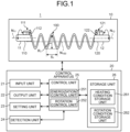
- FIG. 1 is a diagram illustrating a schematic configuration of a heating system according to a first embodiment of the present invention.
- a heating system 1 illustrated in FIG. 1 is, for example, a system for implementing hardening of a coil spring 100.
- the heating system 1 includes a heating apparatus 10 that holds and heats up the coil spring 100, and a control apparatus 20 that controls the heating apparatus 10.
- the coil spring 100 is formed of a wire wound spirally about a predetermined axis (N 100 herein).
- the heating apparatus 10 includes a first shaft member 11 and a second shaft member 12.
- the first shaft member 11 rotates about an axis N 11 (a rotation axis) passing through the center of a shaft body 110 extending in a cylindrical shape, the axis N 11 extending parallel to a longitudinal direction. Furthermore, the first shaft member 11 has, provided therein, a spring holding unit 111 fixed to a lateral surface of the shaft body 110 and configured to hold one end of the coil spring 100. The spring holding unit 111 has, provided therein, a grasping portion 112 configured to have the one end of the coil spring 100 interposed between the grasping portion 112 and an outer peripheral surface of the shaft body 110. The spring holding unit 111 rotates integrally with the shaft body 110.
- the second shaft member 12 rotates about an axis N 12 (a rotation axis) passing through the center of a shaft body 120 extending in a cylindrical shape, the axis N 12 extending parallel to a longitudinal direction. Furthermore, the second shaft member 12 has, provided therein, a spring holding unit 121 fixed to a lateral surface of the shaft body 120 and configured to hold the other end of the coil spring 100.
- the spring holding unit 121 has, provided therein, a grasping portion 122 configured to have the other end of the coil spring 100 interposed between the grasping portion 122 and an outer peripheral surface of the shaft body 120.
- the spring holding unit 121 rotates integrally with the shaft body 120.
- the axis N 11 and the axis N 12 may be not exactly on the same straight line as long as rotation control of the coil spring 100 is not hindered.
- FIG. 1 illustrates an example where the central axis N 100 is not aligned with the axis N 11 and the axis N 12 , but the central axis N 100 may be arranged to coincide with the axis N 11 and the axis N 12 .
- the coil spring 100 rotates about axes parallel to the central axis N 100 and positioned at positions different from each other.
- the coil spring 100 rotates about the central axis N 100 .
- An angle of the central axis N 100 and the axis N 11 and axis N 12 to a horizontal direction is set to 0 degrees or more and 30 degrees or less. This angle is set according to, for example, properties of the coil spring.
- the horizontal direction referred to herein is a direction perpendicular to a gravitational direction (vertical direction).
- shaft body 110 of the first shaft member 11 and the shaft body 120 of the second shaft member 12 are formed by use of an electrically conducting material. Furthermore, these shaft bodies and the control apparatus 20 are connected to each other by electric wires not illustrated in the drawings.
- FIG. 2 is a diagram for illustration of a configuration of main parts of the heating system according to the first embodiment of the present invention.
- FIG. 2 is a diagram illustrating a configuration and operation of a shaft body and a spring holding unit.
- FIG. 2 illustrates the first shaft member 11, but the second shaft member 12 operates similarly.
- the spring holding unit 111 In response to rotation of the shaft body 110, the spring holding unit 111 also rotates in association with the rotation. In this rotation, under control by the control apparatus 20, the shaft body 110 reciprocates by a rotation angle ⁇ .
- the spring holding unit 111 reciprocates between a position P R rotated clockwise from a reference position P S by a rotation angle ⁇ /2 and a position P L rotated anticlockwise from the reference position P S by the rotation angle ⁇ /2.
- an end portion of the coil spring 100 also moves along an outer circumference of the shaft body 110 in accordance with the rotation of the shaft body 110.
- the rotation angle ⁇ is able to be set according to a type of the coil spring 100, and for example, is set to an angle in a range of 90 degrees ( ⁇ 45 degrees) or more and 360 degrees or less.
- the shaft members are configured such that amounts of their rotation are able to be measured by use of encoders, for example.
- the control apparatus 20 includes an input unit 21, an output unit 22, a setting unit 23, a detection unit 24, a control unit 25, and a storage unit 26.
- the input unit 21 receives input of various signals related to operation of the heating system 1.
- the input unit 21 is configured by use of a keyboard, a mouse, a switch, and/or a touch panel, for example.
- the output unit 22 causes an image to be displayed or causes sound or light to be output.
- the output unit 22 is configured by use of a display, a speaker, and/or a light source, for example.
- the setting unit 23 performs setting of heating conditions. Based on setting information received by the input unit 21 and/or information stored in the storage unit 26, for example, the setting unit 23 sets a heating temperature and a heating time period for the coil spring 100, a rotation angle of the shaft members, a rotation velocity of the shaft members, and electric energy to energize the shaft members.
- the detection unit 24 detects a temperature of the coil spring 100.
- the detection unit 24 may detect a temperature of each of the shaft members.
- the control unit 25 controls operation of each component of the heating system 1. Furthermore, the control unit 25 has an energization control unit 251, and a rotation control unit 252. For example, in response to input of an instruction to start a heating process via the input unit 21, the energization control unit 251 starts passing an electric current through the first shaft member 11 and the second shaft member 12. Furthermore, the rotation control unit 252 rotates the first shaft member 11 and the second shaft member 12 in a set pattern in the heating process.
- the setting unit 23, the detection unit 24, and the control unit 25 are each configured by use of a processor, such as a central processing unit (CPU), or a processor that is any one of various arithmetic circuits that execute specific functions, such as an application specific integrated circuit (ASIC), for example.
- a processor such as a central processing unit (CPU), or a processor that is any one of various arithmetic circuits that execute specific functions, such as an application specific integrated circuit (ASIC), for example.
- CPU central processing unit
- ASIC application specific integrated circuit
- the storage unit 26 stores therein, for example, a program (for example, a program executed in the heating process) for the control unit 25 to executes various kinds of operation. Furthermore, the storage unit 26 has a heating condition storage unit 261 that stores heating conditions for hardening of the coil spring 100 and programs and parameters for the heating process, and a rotation condition storage unit 262 that stores rotation conditions for the rotation control of the coil spring 100 and programs and parameters for the rotation control.
- the storage unit 26 is configured by use of a volatile memory or a non-volatile memory, or is configured of a combination of a volatile memory and a non-volatile memory. For example, the storage unit 26 is configured by use of a random access memory (RAM) and a read only memory (ROM).
- RAM random access memory
- ROM read only memory
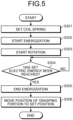
- FIG. 3 is a flowchart illustrating the heating method according to the first embodiment of the present invention. Each unit is hereinafter assumed to operate under control by the control apparatus 20.
- the coil spring 100 is set in the heating apparatus 10 (Step S101). Specifically, the one end of the coil spring 100 is grasped by the grasping portion 112 and the shaft body 110 and the other end is grasped by the grasping portion 122 and the shaft body 120. Both of these ends of the coil spring 100 are thereby fixed to the first shaft member 11 and the second shaft member 12.
- the energization control unit 251 starts passing an electric current through the first shaft member 11 and the second shaft member 12 (Step S102).
- the energization control unit 251 is triggered by an energization start instruction received by the input unit 21 to start energization control.
- Energization results in flow of an electric current through the coil spring 100 via the first shaft member 11 and the second shaft member 12 and generation of heat. This heat heats up the coil spring.
- the energization control unit 251 performs control of passing an electric current to the first shaft member 11 and the second shaft member 12, the electric current causing the heated temperature of the coil spring 100 to rise to the heating temperature set by the setting unit 23.
- the rotation control unit 252 starts rotation of the first shaft member 11 and the second shaft member 12 (Step S103).
- the rotation control unit 252 rotates the shaft bodies 110 and 120 at the rotation velocity and rotation angle that have been set.
- the rotation control unit 252 rotates the shaft bodies 110 and 120 such that the shaft bodies 110 and 120 operate in synchronization with each other.
- the rotation velocity is set based on variation in spaces between coils of a wire of the coil spring 100 and/or variation in diameters of the coils of the coil spring 100.
- the rotation may be started at the same time as the start of the energization or may be started after elapse of a set time period from the start of the energization.
- the energization control unit 251 determines whether or not the temperature of the coil spring 100 has reached the set temperature (Step S104). In a case where the energization control unit 251 determines, based on the temperature detected by the detection unit 24, that the temperature of the coil spring 100 has not reached the set temperature (Step S104: No), the energization control unit 251 repeats the check of the temperature. On the contrary, in a case where the energization control unit 251 determines that the temperature of the coil spring 100 has reached the set temperature (Step S104: Yes), the energization control unit 251 proceeds to Step S105.
- the set temperature is set to a temperature equal to or higher than a transformation temperature of the material forming the coil spring 100.
- Step S105 the energization control unit 251 ends passing the electric current through the shaft members.
- the rotation control unit 252 rotates the shaft bodies 110 and 120 to move positions of the grasping portions 112 and 122 to set positions that have been set beforehand and the heating process is thereby ended (Step S106).
- the set positions herein are, for examples, positions for conveying the coil spring 100 to a process subsequent to the heating process. Specifically, positions where the coil spring 100 is easily grasped by a conveyance arm are set, for example.
- the energization and the rotation may be ended at the same time or the rotation may be ended first.
- the end portions of the coil spring are fixed by being respectively grasped by the outer peripheral surfaces of the shaft bodies, the shaft members are rotated while the coil spring 100 is energized via the shaft bodies, and the coil spring 100 is heated while being rotated.
- the first embodiment implements uniform heating of the coil spring by rotation of the coil spring 100 during heating and thereby enables minimization of variation in spaces between the coils of the wire of the coil spring and variation in the diameters of the coils formed by winding.
- FIG. 4 is a flowchart illustrating a heating method according to the first modified example of the present invention.
- Each unit is hereinafter assumed to operate under control by the control apparatus 20.
- the detection unit 24 is assumed to detect an energization time period.
- Steps S201 to S203 similarly to Steps S101 to S103 illustrated in FIG. 3 , the coil spring 100 is set in the heating apparatus 10 and passage of an electric current through and rotation of the first shaft member 11 and the second shaft member 12 are started (Steps S201 to S203).
- the energization control unit 251 determines whether or not the energization time period has reached a set time period that has been set beforehand (Step S204). In a case where the energization control unit 251 determines, based on the energization time period detected by the detection unit 24, that the energization time period has not reached the set time period (Step S204: No), the energization control unit 251 repeats the check of the time elapsed. On the contrary, in a case where the energization control unit 251 determines that the energization time period has reached the set time period (Step S204: Yes), the energization control unit 251 proceeds to Step S205. A time period is set as the set time period set then, for example, the time period being a time period required for the coil spring 100 to reach the temperature equal to or higher than the transformation temperature of the material forming the coil spring 100.
- the end portions of the coil spring are fixed by being respectively grasped by the outer peripheral surfaces of the shaft bodies, the shaft members are rotated while the coil spring 100 is energized via the shaft bodies, and the coil spring 100 is heated while being rotated.
- the second modified example implements uniform heating of the coil spring by rotation of the coil spring 100 during heating and thereby enables minimization of variation in the spaces between the coils of the wire of the coil spring and variation in the diameters of the coils formed by the winding.
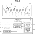
- FIG. 8 is a diagram illustrating a schematic configuration of a heating system according to the first modified example of the second embodiment of the present invention.
- a heating system 1B according to the first modified example includes a heating apparatus 10B instead of the heating apparatus 10A.
- a control apparatus 20 has the same configuration as that of the second embodiment and description thereof will thus be omitted.
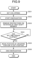
- the stoppage or continuation is determined by use of one of a temperature, a heating time period, and electric energy, but without being limited to this example, the control may be performed by combination of a temperature, a time period, and electric energy.
Landscapes
- Chemical & Material Sciences (AREA)
- Engineering & Computer Science (AREA)
- Mechanical Engineering (AREA)
- Physics & Mathematics (AREA)
- Thermal Sciences (AREA)
- Crystallography & Structural Chemistry (AREA)
- Materials Engineering (AREA)
- Metallurgy (AREA)
- Organic Chemistry (AREA)
- General Engineering & Computer Science (AREA)
- Heat Treatment Of Articles (AREA)
- Wire Processing (AREA)
Applications Claiming Priority (3)
| Application Number | Priority Date | Filing Date | Title |
|---|---|---|---|
| JP2022057252A JP2023148954A (ja) | 2022-03-30 | 2022-03-30 | 加熱方法および加熱システム |
| JP2022057253A JP7820210B2 (ja) | 2022-03-30 | 2022-03-30 | 加熱方法および加熱システム |
| PCT/JP2022/043525 WO2023188536A1 (ja) | 2022-03-30 | 2022-11-25 | 加熱方法および加熱システム |
Publications (2)
| Publication Number | Publication Date |
|---|---|
| EP4502194A1 true EP4502194A1 (de) | 2025-02-05 |
| EP4502194A4 EP4502194A4 (de) | 2025-07-02 |
Family
ID=88199956
Family Applications (1)
| Application Number | Title | Priority Date | Filing Date |
|---|---|---|---|
| EP22935665.4A Pending EP4502194A4 (de) | 2022-03-30 | 2022-11-25 | Heizverfahren und heizsystem |
Country Status (5)
| Country | Link |
|---|---|
| US (1) | US20250207214A1 (de) |
| EP (1) | EP4502194A4 (de) |
| CN (1) | CN119032186A (de) |
| MX (1) | MX2024011815A (de) |
| WO (1) | WO2023188536A1 (de) |
Family Cites Families (6)
| Publication number | Priority date | Publication date | Assignee | Title |
|---|---|---|---|---|
| JPS6130246A (ja) * | 1984-07-19 | 1986-02-12 | Toshikazu Okuno | スプリングの加熱装置 |
| US6235131B1 (en) * | 1999-07-09 | 2001-05-22 | Mathew Warren Industries, Inc. | System for heat treating coiled springs |
| US8506732B2 (en) * | 2009-08-07 | 2013-08-13 | Radyne Corporation | Heat treatment of helical springs or similarly shaped articles by electric resistance heating |
| JP5574772B2 (ja) * | 2010-03-23 | 2014-08-20 | 中央発條株式会社 | ばねの通電加熱方法及びその装置 |
| US9623475B2 (en) * | 2010-07-26 | 2017-04-18 | Chuo Hatsujo Kabushiki Kaisha | Method for producing spring |
| WO2013099821A1 (ja) * | 2011-12-26 | 2013-07-04 | 中央発條株式会社 | ばねの製造方法及びばね |
-
2022
- 2022-11-25 WO PCT/JP2022/043525 patent/WO2023188536A1/ja not_active Ceased
- 2022-11-25 CN CN202280093192.8A patent/CN119032186A/zh active Pending
- 2022-11-25 EP EP22935665.4A patent/EP4502194A4/de active Pending
- 2022-11-25 US US18/848,292 patent/US20250207214A1/en active Pending
-
2024
- 2024-09-26 MX MX2024011815A patent/MX2024011815A/es unknown
Also Published As
| Publication number | Publication date |
|---|---|
| CN119032186A (zh) | 2024-11-26 |
| EP4502194A4 (de) | 2025-07-02 |
| MX2024011815A (es) | 2024-11-08 |
| US20250207214A1 (en) | 2025-06-26 |
| WO2023188536A1 (ja) | 2023-10-05 |
Similar Documents
| Publication | Publication Date | Title |
|---|---|---|
| KR102268968B1 (ko) | 유도 발열 롤러 장치, 및 유도 코일의 온도 검출 기구 | |
| KR101508108B1 (ko) | 스피닝 성형 장치 및 성형 방법 | |
| JP7603281B2 (ja) | スプリングバック量予測方法、異形鉄筋の曲げ加工方法 | |
| US20220319935A1 (en) | Method of measuring resistivity, method of manufacturing semiconductor device, recording medium, and resistivity measuring device | |
| US20250207214A1 (en) | Heating method and heating system | |
| JP6435112B2 (ja) | スピニング成形装置 | |
| JP7276270B2 (ja) | テンション装置 | |
| JPH09225542A (ja) | 被加工チューブの曲げ装置 | |
| JP7820210B2 (ja) | 加熱方法および加熱システム | |
| JP2954504B2 (ja) | 加熱ローラの製造方法および製造装置 | |
| JP2023148954A (ja) | 加熱方法および加熱システム | |
| EP3343052A1 (de) | Magnetlager und feuerverzinkungsvorrichtung damit | |
| WO2007123218A1 (ja) | 巻線機 | |
| JP2006006689A (ja) | 均一磁場発生装置 | |
| JP4506148B2 (ja) | インダクタの製造装置 | |
| JP7339119B2 (ja) | 磁気センサの検査装置、磁気センサの検査方法 | |
| US11602781B2 (en) | Spherical coil winding machine | |
| JP2020056585A (ja) | 磁気測定装置及び磁気測定方法 | |
| JP2005228571A (ja) | 電磁誘導加熱コイルおよび電磁誘導加熱装置 | |
| US20210068209A1 (en) | Rotary heating apparatus, and methods of making and using same | |
| JP2003275670A (ja) | 円筒状部材の製造方法および製造装置 | |
| JP4865681B2 (ja) | 測定装置および測定方法 | |
| JPS6182939A (ja) | 鋼線材の曲り矯正装置 | |
| JP2025024521A (ja) | 鉄筋曲機及び鉄筋曲げ方法 | |
| KR102794092B1 (ko) | 파이프 내부 연마용 전극 위치 측정장치 |
Legal Events
| Date | Code | Title | Description |
|---|---|---|---|
| STAA | Information on the status of an ep patent application or granted ep patent |
Free format text: STATUS: THE INTERNATIONAL PUBLICATION HAS BEEN MADE |
|
| PUAI | Public reference made under article 153(3) epc to a published international application that has entered the european phase |
Free format text: ORIGINAL CODE: 0009012 |
|
| STAA | Information on the status of an ep patent application or granted ep patent |
Free format text: STATUS: REQUEST FOR EXAMINATION WAS MADE |
|
| 17P | Request for examination filed |
Effective date: 20240917 |
|
| AK | Designated contracting states |
Kind code of ref document: A1 Designated state(s): AL AT BE BG CH CY CZ DE DK EE ES FI FR GB GR HR HU IE IS IT LI LT LU LV MC ME MK MT NL NO PL PT RO RS SE SI SK SM TR |
|
| A4 | Supplementary search report drawn up and despatched |
Effective date: 20250602 |
|
| RIC1 | Information provided on ipc code assigned before grant |
Ipc: C21D 9/00 20060101ALI20250526BHEP Ipc: C21D 11/00 20060101ALI20250526BHEP Ipc: C21D 1/40 20060101ALI20250526BHEP Ipc: C21D 1/18 20060101ALI20250526BHEP Ipc: F27D 11/04 20060101ALI20250526BHEP Ipc: H05B 3/00 20060101ALI20250526BHEP Ipc: B21F 35/00 20060101ALI20250526BHEP Ipc: C21D 9/02 20060101AFI20250526BHEP |
|
| DAV | Request for validation of the european patent (deleted) | ||
| DAX | Request for extension of the european patent (deleted) |