EP4502379A1 - Compresseur électrique et procédé d'assemblage de compresseur électrique - Google Patents
Compresseur électrique et procédé d'assemblage de compresseur électrique Download PDFInfo
- Publication number
- EP4502379A1 EP4502379A1 EP23779907.7A EP23779907A EP4502379A1 EP 4502379 A1 EP4502379 A1 EP 4502379A1 EP 23779907 A EP23779907 A EP 23779907A EP 4502379 A1 EP4502379 A1 EP 4502379A1
- Authority
- EP
- European Patent Office
- Prior art keywords
- cluster block
- housing
- mating
- bottom wall
- stator core
- Prior art date
- Legal status (The legal status is an assumption and is not a legal conclusion. Google has not performed a legal analysis and makes no representation as to the accuracy of the status listed.)
- Pending
Links
Images






Classifications
-
- H—ELECTRICITY
- H02—GENERATION; CONVERSION OR DISTRIBUTION OF ELECTRIC POWER
- H02K—DYNAMO-ELECTRIC MACHINES
- H02K3/00—Details of windings
- H02K3/46—Fastening of windings on the stator or rotor structure
- H02K3/52—Fastening salient pole windings or connections thereto
- H02K3/521—Fastening salient pole windings or connections thereto applicable to stators only
- H02K3/522—Fastening salient pole windings or connections thereto applicable to stators only for generally annular cores with salient poles
-
- F—MECHANICAL ENGINEERING; LIGHTING; HEATING; WEAPONS; BLASTING
- F04—POSITIVE - DISPLACEMENT MACHINES FOR LIQUIDS; PUMPS FOR LIQUIDS OR ELASTIC FLUIDS
- F04B—POSITIVE-DISPLACEMENT MACHINES FOR LIQUIDS; PUMPS
- F04B35/00—Piston pumps specially adapted for elastic fluids and characterised by the driving means to their working members, or by combination with, or adaptation to, specific driving engines or motors, not otherwise provided for
- F04B35/04—Piston pumps specially adapted for elastic fluids and characterised by the driving means to their working members, or by combination with, or adaptation to, specific driving engines or motors, not otherwise provided for the means being electric
-
- F—MECHANICAL ENGINEERING; LIGHTING; HEATING; WEAPONS; BLASTING
- F04—POSITIVE - DISPLACEMENT MACHINES FOR LIQUIDS; PUMPS FOR LIQUIDS OR ELASTIC FLUIDS
- F04B—POSITIVE-DISPLACEMENT MACHINES FOR LIQUIDS; PUMPS
- F04B39/00—Component parts, details, or accessories, of pumps or pumping systems specially adapted for elastic fluids, not otherwise provided for in, or of interest apart from, groups F04B25/00 - F04B37/00
- F04B39/12—Casings; Cylinders; Cylinder heads; Fluid connections
- F04B39/121—Casings
-
- F—MECHANICAL ENGINEERING; LIGHTING; HEATING; WEAPONS; BLASTING
- F04—POSITIVE - DISPLACEMENT MACHINES FOR LIQUIDS; PUMPS FOR LIQUIDS OR ELASTIC FLUIDS
- F04C—ROTARY-PISTON, OR OSCILLATING-PISTON, POSITIVE-DISPLACEMENT MACHINES FOR LIQUIDS; ROTARY-PISTON, OR OSCILLATING-PISTON, POSITIVE-DISPLACEMENT PUMPS
- F04C18/00—Rotary-piston pumps specially adapted for elastic fluids
- F04C18/02—Rotary-piston pumps specially adapted for elastic fluids of arcuate-engagement type, i.e. with circular translatory movement of co-operating members, each member having the same number of teeth or tooth-equivalents
- F04C18/0207—Rotary-piston pumps specially adapted for elastic fluids of arcuate-engagement type, i.e. with circular translatory movement of co-operating members, each member having the same number of teeth or tooth-equivalents both members having co-operating elements in spiral form
- F04C18/0215—Rotary-piston pumps specially adapted for elastic fluids of arcuate-engagement type, i.e. with circular translatory movement of co-operating members, each member having the same number of teeth or tooth-equivalents both members having co-operating elements in spiral form where only one member is moving
-
- F—MECHANICAL ENGINEERING; LIGHTING; HEATING; WEAPONS; BLASTING
- F04—POSITIVE - DISPLACEMENT MACHINES FOR LIQUIDS; PUMPS FOR LIQUIDS OR ELASTIC FLUIDS
- F04C—ROTARY-PISTON, OR OSCILLATING-PISTON, POSITIVE-DISPLACEMENT MACHINES FOR LIQUIDS; ROTARY-PISTON, OR OSCILLATING-PISTON, POSITIVE-DISPLACEMENT PUMPS
- F04C23/00—Combinations of two or more pumps, each being of rotary-piston or oscillating-piston type, specially adapted for elastic fluids; Pumping installations specially adapted for elastic fluids; Multi-stage pumps specially adapted for elastic fluids
- F04C23/008—Hermetic pumps
-
- F—MECHANICAL ENGINEERING; LIGHTING; HEATING; WEAPONS; BLASTING
- F04—POSITIVE - DISPLACEMENT MACHINES FOR LIQUIDS; PUMPS FOR LIQUIDS OR ELASTIC FLUIDS
- F04C—ROTARY-PISTON, OR OSCILLATING-PISTON, POSITIVE-DISPLACEMENT MACHINES FOR LIQUIDS; ROTARY-PISTON, OR OSCILLATING-PISTON, POSITIVE-DISPLACEMENT PUMPS
- F04C2230/00—Manufacture
- F04C2230/60—Assembly methods
-
- F—MECHANICAL ENGINEERING; LIGHTING; HEATING; WEAPONS; BLASTING
- F04—POSITIVE - DISPLACEMENT MACHINES FOR LIQUIDS; PUMPS FOR LIQUIDS OR ELASTIC FLUIDS
- F04C—ROTARY-PISTON, OR OSCILLATING-PISTON, POSITIVE-DISPLACEMENT MACHINES FOR LIQUIDS; ROTARY-PISTON, OR OSCILLATING-PISTON, POSITIVE-DISPLACEMENT PUMPS
- F04C2240/00—Components
- F04C2240/40—Electric motor
-
- F—MECHANICAL ENGINEERING; LIGHTING; HEATING; WEAPONS; BLASTING
- F04—POSITIVE - DISPLACEMENT MACHINES FOR LIQUIDS; PUMPS FOR LIQUIDS OR ELASTIC FLUIDS
- F04C—ROTARY-PISTON, OR OSCILLATING-PISTON, POSITIVE-DISPLACEMENT MACHINES FOR LIQUIDS; ROTARY-PISTON, OR OSCILLATING-PISTON, POSITIVE-DISPLACEMENT PUMPS
- F04C2240/00—Components
- F04C2240/80—Other components
- F04C2240/803—Electric connectors or cables; Fittings therefor
-
- F—MECHANICAL ENGINEERING; LIGHTING; HEATING; WEAPONS; BLASTING
- F04—POSITIVE - DISPLACEMENT MACHINES FOR LIQUIDS; PUMPS FOR LIQUIDS OR ELASTIC FLUIDS
- F04C—ROTARY-PISTON, OR OSCILLATING-PISTON, POSITIVE-DISPLACEMENT MACHINES FOR LIQUIDS; ROTARY-PISTON, OR OSCILLATING-PISTON, POSITIVE-DISPLACEMENT PUMPS
- F04C2240/00—Components
- F04C2240/80—Other components
- F04C2240/808—Electronic circuits (e.g. inverters) installed inside the machine
-
- H—ELECTRICITY
- H02—GENERATION; CONVERSION OR DISTRIBUTION OF ELECTRIC POWER
- H02K—DYNAMO-ELECTRIC MACHINES
- H02K2203/00—Specific aspects not provided for in the other groups of this subclass relating to the windings
- H02K2203/09—Machines characterised by wiring elements other than wires, e.g. bus rings, for connecting the winding terminations
-
- H—ELECTRICITY
- H02—GENERATION; CONVERSION OR DISTRIBUTION OF ELECTRIC POWER
- H02K—DYNAMO-ELECTRIC MACHINES
- H02K2211/00—Specific aspects not provided for in the other groups of this subclass relating to measuring or protective devices or electric components
- H02K2211/03—Machines characterised by circuit boards, e.g. pcb
-
- H—ELECTRICITY
- H02—GENERATION; CONVERSION OR DISTRIBUTION OF ELECTRIC POWER
- H02K—DYNAMO-ELECTRIC MACHINES
- H02K5/00—Casings; Enclosures; Supports
- H02K5/04—Casings or enclosures characterised by the shape, form or construction thereof
- H02K5/15—Mounting arrangements for bearing-shields or end plates
-
- H—ELECTRICITY
- H02—GENERATION; CONVERSION OR DISTRIBUTION OF ELECTRIC POWER
- H02K—DYNAMO-ELECTRIC MACHINES
- H02K5/00—Casings; Enclosures; Supports
- H02K5/04—Casings or enclosures characterised by the shape, form or construction thereof
- H02K5/16—Means for supporting bearings, e.g. insulating supports or means for fitting bearings in the bearing-shields
- H02K5/173—Means for supporting bearings, e.g. insulating supports or means for fitting bearings in the bearing-shields using bearings with rolling contact, e.g. ball bearings
- H02K5/1732—Means for supporting bearings, e.g. insulating supports or means for fitting bearings in the bearing-shields using bearings with rolling contact, e.g. ball bearings radially supporting the rotary shaft at both ends of the rotor
Definitions
- the present invention relates to an improved electric compressor in which a motor for driving a compression mechanism is housed in a bottomed cylindrical housing, and an improved method for assembling an electric compressor.
- Electric compressors include those of the "closed on the control unit side" type, in which a stator core of a motor is fixed to an inner circumferential surface of a bottomed cylindrical housing, and a control unit (a motor drive circuit such as an inverter) for controlling driving of the motor is provided on an outer wall surface of a bottom wall of the housing.
- a control unit a motor drive circuit such as an inverter
- Patent Document 1 the technology of Patent Document 1 is known as such an electric compressor.
- connection terminal is accommodated in a cluster block.
- This cluster block is disposed in a space between the bottom wall of the housing and the coil end.
- the conduction member protrudes into the housing from the outer wall surface side of the bottom wall through a through-hole, and is connected to the connection terminal by insertion into the cluster block.
- the procedure for assembling the conduction member with the connection terminal in the cluster block is as follows.
- the stator core is first of all fixed inside the housing.
- the cluster block accommodating the connection terminal is positioned, together with the motor wiring, between the coil end of the stator core and the bottom wall of the housing.
- a pressing jig is then inserted inside the cylindrical stator core from an opening side of the housing. At this point, the pressing jig and the cluster block are positioned in relation to each other by mating of a pin and a hole.
- the cluster block is then pressed against the bottom wall of the housing by means of the pressing jig.
- the cluster block is in a state of being sandwiched between the pressing jig and the bottom wall.
- the conduction member protrudes into the housing from the outer wall surface side of the bottom wall, and connects with the connection terminal inside the cluster block by means of insertion.
- a fixing structure employing an "interference fit” exists as a configuration for fixing the stator core to the inner circumferential surface of the bottomed cylindrical housing.
- a process employing a shrink fit is an example of an interference fit. According to a shrink fit process, an inner diameter of the housing is formed slightly smaller than an outer diameter of the stator core, the housing is thermally expanded by being placed in a high-temperature state, and the normal-temperature stator core is fitted into the thermally-expanded housing, after which the housing is returned to normal temperature whereby the housing contracts and the stator core can be fixed in the housing.
- the present invention has been devised in order to solve the difficulty above, and the problem addressed by the present invention lies in providing technology for an electric compressor in which a stator core is fixed inside a bottomed cylindrical housing, wherein contact between a cluster block and the housing is avoided so that protection performance can be improved.
- the present invention provides an electric compressor comprising: a compression mechanism (50) for compressing a gas, a motor (100) for driving the compression mechanism (50), a control unit (140) for controlling driving of the motor (100), and a housing (20) which is a bottomed cylindrical member for internally housing the motor (100); the control unit (140) being provided on an outer wall surface (21a) of a bottom wall (21) of the housing (20); the motor (100) comprising a rotor (102) whose rotational axis is aligned with a longitudinal direction of the housing (20), and a cylindrical stator (103) disposed radially outside the rotor (102); the stator (103) including: a cylindrical stator core (111) which is positioned with a space from the bottom wall (21) and is also fixed to an inner circumferential surface (20a) of the housing (20), a coil (114) wound around the stator core (111), and a connection terminal (116) which is disposed on the bottom wall (21) side and is electrically connected to the coil (
- the cluster block has the mating portion enabling mating so that the cluster block can be held by the holding jig by means of a frictional force therebetween.
- the cluster block in a state of being positioned with a gap from the bottom wall of the housing can therefore be held in an optimum state by means of the holding jig without inclination. Accordingly, the cluster block can be appropriately arranged so as not to contact the housing. For example, even if the structure for fixing the stator core to the inner circumferential surface of the housing comprises fixing by means of an interference fit employing a shrink fit process, the position of the cluster block can be held by means of the holding jig so that the cluster block does not contact the heated housing. Performance in terms of protecting the cluster block can be improved as a result.
- Mating of the mating portion (125; 225) with the holding jig (150; 250) preferably constitutes a mating configuration capable of holding a mated state by means of a frictional force therebetween and also enabling detachment from each other by means of a detaching force.
- Mating of the mating portion with the holding jig constitutes a "light press fit", which is mating capable of holding the mated state by means of a frictional force therebetween and also enabling detachment from each other by means of a detaching force.
- the cluster block can therefore be stably held by means of the holding jig in the space between the bottom wall and the stator core while also being removable and accurately positionable.
- the cluster block (120; 220) comprises a facing surface (123a) facing the stator (103);
- the stator (103) further comprises an insulator (112) which is provided on an end face (111a) of the stator core (111) on the control unit (140) side, and is sandwiched between the stator core (111) and the coil (114); and the insulator (112) comprises an outer circumferential-side first support face (112d) and an inner circumferential-side second support face (112e) capable of supporting the facing surface (123a) of the cluster block (120; 220).
- the facing surface of the cluster block can therefore be supported (movement of the cluster block can be restricted) by means of the first and second support faces of the insulator when the holding jig is withdrawn after the stator core has been fixed to the inner circumferential surface of the housing. Accordingly, it is easy to withdraw the holding jig from the cluster block.
- the cluster block is supported at the two locations of the outer circumferential-side first support face and the inner circumferential-side second support face, and the cluster block can therefore be stably supported. Consequently, the cluster block which is disposed toward the axial direction of the rotor (the radially inner side of the rotor) can be stably supported by means of the insulator so that the cluster block does not contact the inner circumferential surface of the heated housing.
- the cluster block can be supported in the axial direction (a direction along the center line of the stator core) by means of the first and second support faces when the sealed terminal is inserted into the connection terminal of the cluster block. Consequently, the sealed terminal can be easily assembled with the connection terminal.
- the facing surface (123a) of the cluster block (120; 220) is positioned up to a radially inner side of the cylindrical stator core (111); and the mating portion (125; 225) is configured by recessed mating recesses (126, 126; 226, 227) formed on a radially inside part (123b) of the facing surface (123a).
- a mating distance on a part of the facing surface of the cluster block facing the stator cannot be set to a long distance because the overall length of the electric compressor is reduced by bringing the stator and the cluster block close together.
- the mating distance on the radially inside part can be set longer to an extent that there is no interference with the end face of the rotor, which therefore stabilizes the position and attitude of the cluster block, enabling very accurate positioning.
- the mating recesses (126, 126) are configured by a pair of arc-shaped grooves centered on the axis (CL1) of the rotor (102), and are positioned at a circumferential interval (Ln1) from each other.
- the pair of arc-shaped grooves are mated with the holding jig whereby it is possible to restrict relative movement of the cluster block with respect to the holding jig in both a direction orthogonal to the axis of the rotor and a rotation direction about the axis of the rotor.
- the cluster block can therefore be positioned very accurately in relation to the holding jig.
- the mating recesses (226, 227) are configured by a pair of holes, and are positioned at an interval (Ln3) from each other.
- the pair of holes are mated with the holding jig whereby it is possible to restrict relative movement of the cluster block with respect to the holding jig in both the direction orthogonal to the axis of the rotor and the rotation direction about the axis of the rotor.
- the cluster block can therefore be positioned very accurately in relation to the holding jig.
- the mating recesses are configured by the pair of holes and therefore have a simple construction.
- a cluster block receiving portion (28) for receiving the cluster block (120; 220) is formed on an inner wall surface (21b) of the bottom wall (21) of the housing (20); and the cluster block (120; 220) is disposed in the cluster block receiving portion (28).
- the cluster block can therefore be very efficiently assembled by effectively utilizing the narrow space inside the housing. It is therefore possible to achieve a reduction in the size of the electric compressor.
- the present invention furthermore provides a method for assembling an electric compressor (10; 200) comprising: a compression mechanism (50) for compressing a gas; a motor (100) for driving the compression mechanism (50), the motor (100) comprising a rotor (102), a cylindrical stator core (111) of a stator (103) disposed radially outside the rotor (102), an insulator (112) provided on an end face (111a) of the stator core (111), and a coil (114) wound around the stator core (111) and the insulator (112); a housing (20) which is a bottomed cylindrical member having the stator core (111) fixed to an inner circumferential surface (20a) thereof; a control unit (140) which is provided on an outer wall surface (21a) of a bottom wall (21) of the housing (20) and controls driving of the motor (100); a connection terminal (116) which is disposed on an inner wall surface (21b) side of the bottom wall (21) and is electrically connected to the coil (114
- the cluster block has the mating portion enabling mating so that the cluster block can be held by the holding jig.
- the cluster block in a state of being positioned with a gap from the bottom wall of the housing can therefore be held in an optimum state by means of the holding jig without inclination. Accordingly, when the stator core is fixed to the heated housing by means of shrink fitting, the cluster block can be appropriately arranged so as not to contact the heated housing. Performance in terms of protecting the cluster block can be improved as a result.
- the mating portion of the cluster block is mated to an extent that the holding jig can be detached from the mating portion.
- Mating of the mating portion with the holding jig can thus be afforded by a "light press fit", which is mating capable of holding the mated state and also enabling detachment from each other by means of a detaching force.
- the cluster block can therefore be stably held by means of the holding jig in the space between the bottom wall and a first insulator while also being removable and accurately positionable.
- the present invention makes it possible to improve protection performance in relation to difficulties caused by a cluster block contacting a bottomed cylindrical housing in an electric compressor in which a stator core is fixed inside the housing.
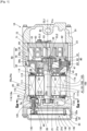
- the electric compressor 10 is suitable for use in a refrigeration cycle employing a refrigerant as a working fluid, and is employed in the refrigeration cycle of an automotive air conditioning device, for example. It should be noted that there is no limitation to the purpose of use of the electric compressor 10.
- the electric compressor 10 comprises, for example: a housing 20 which can be installed horizontally; a compression mechanism 50 for compressing a gas (e.g., a gaseous refrigerant); a motor 100 for driving the compression mechanism 50; and a control unit 140 for controlling driving of the motor 100.
- the control unit 140 is configured by an inverter device for supplying driving electrical power to the motor 100, for example.
- the housing 20 is a bottomed cylindrical member comprising a bottom wall 21 and a circumferential wall 22, and is closed at one end by means of the bottom wall 21 and completely open at another end. That is to say, an opening portion 23 is provided at the other end of the housing 20. The opening portion 23 is closed by an openable/closable head member 31.
- the housing 20 is constructed by a cast piece made of a metallic material such as aluminum (including aluminum alloy).
- An outer wall surface 21a and an inner wall surface 21b of the bottom wall 21 of the housing 20 are flat surfaces.
- a bottomed cylindrical control housing 32 is assembled with the outer wall surface 21a. That is to say, a bottom wall 32a of the control housing 32 is placed over the outer wall surface 21a of the bottom wall 21 of the housing 20 and is also fastened to the bottom wall 21 by means of a fastening member.
- the control unit 140 is accommodated in the control housing 32. As a result, the control unit 140 is provided on the outer wall surface 21a of the bottom wall 21 of the housing 20.
- An opening portion 32b of the control housing 32 is closed off by means of an openable/closable lid 33.
- the control unit 140 will be described in detail later.
- the housing 20 internally comprises a first accommodating chamber 24 on the bottom wall 21 side and a second accommodating chamber 25 on the opening portion 23 side.
- the first and second accommodating chambers 24, 25 are continuous in a longitudinal direction (axial direction) of the housing 20.
- a first inner circumferential surface 24a of the first accommodating chamber 24 and a second inner circumferential surface 25a of the second accommodating chamber 25 are circular about a center line CL1 in the longitudinal direction of the housing 20.
- the second inner circumferential surface 25a has a larger diameter than the first inner circumferential surface 24a.
- the compression mechanism 50 is at least partly (e.g., completely) accommodated on the opening portion 23 side inside the housing 20, i.e., in the second accommodating chamber 25.
- the motor 100 is accommodated on the bottom wall 21 side inside the housing 20, i.e., in the first accommodating chamber 24.
- the housing 20 further comprises an intake port 26 for taking the refrigerant into the first accommodating chamber 24 from the outside.
- the head member 31 comprises: an oil separation chamber 31a for separating oil from the refrigerant compressed by means of the compression mechanism 50; and a discharge port (not depicted) for discharging to the outside the gaseous refrigerant from which the oil has been separated by means of the oil separation chamber 31a.
- a partition is formed between the first accommodating chamber 24 and the second accommodating chamber 25 by means of a disc-shaped partition member 34 (also referred to as a drive shaft support member 34).
- the partition member 34 restricts both relative rotation and relative movement in the axial direction with respect to the housing 20.
- the drive shaft support member 34 is fixed to the housing 20 after the motor 100 has been housed in the housing 20.
- the first accommodating chamber 24 may also be referred to below as the "low-pressure chamber 24".
- the partition member 34 comprises a plurality of intake holes 34a providing communication between the first accommodating chamber 24 and the second accommodating chamber 25.
- the partition member 34 may be considered as a component of the compression mechanism 50. Even if the partition wall 34 is considered as part of the compression mechanism 50, this does not depart from the essential point of the present invention.
- a drive shaft 41 positioned on the center line CL1 in the longitudinal direction of the housing 20 is provided in the first accommodating chamber 24.
- the drive shaft 41 includes both a configuration in which it also serves as an output shaft 101 (motor shaft 101) of the motor 100, and a configuration in which it is a separate member (not depicted) from the output shaft 101 of the motor 100. In the description given here, the drive shaft 41 is configured to also serve as the output shaft 101 of the motor 100.
- the center line CL1 in the longitudinal direction of the housing 20 may also be referred to as the "center line CL1 of the drive shaft 41 (output shaft 101)".
- the drive shaft 41 penetrates the partition member 34 toward the compression mechanism 50 side, and is rotatably supported by means of a first bearing 42 provided in the partition member 34 and a second bearing 43 provided in a bearing holding portion 21c in the bottom wall 21 of the housing 20.
- the drive shaft 41 further comprises an eccentric shaft 44 on one end face penetrating the partition member 34.
- the eccentric shaft 44 extends from one end face of the drive shaft 41 toward the compression mechanism 50 and is parallel with the drive shaft 41.
- a center line CL2 of the eccentric shaft 44 is offset from the center line CL1 of the drive shaft 41.
- An annular bush 45 is rotatably mated with the eccentric shaft 44.
- a radially-protruding counterweight 46 is integrally provided with the bush 45.
- An inner circumferential surface of a third bearing 47 is mated with an outer circumferential surface of the bush 45.
- the compression mechanism 50 will be described next.
- the compression mechanism 50 is configured, for example, by a "scroll compression mechanism" which compresses a gas (e.g., a gaseous refrigerant) by means of a combination of a fixed scroll 60 which is supported between the head member 31 and the partition member 34 in such a way as to be incapable of relative rotation, and an orbiting scroll 70 capable of orbiting in the circumferential direction in relation to the fixed scroll 60.
- a gas e.g., a gaseous refrigerant
- the fixed scroll 60 comprises a disc-shaped fixed panel 61, a cylindrical outer circumferential wall 62, and a spiral-shaped fixed spiral wall 63.
- the fixed panel 61 is orthogonal to the center line CL2 of the eccentric shaft 44.
- the outer circumferential wall 62 extends from an outer circumferential edge of the fixed panel 61 to the motor 100 side.
- a refrigerant intake port 64 for taking the refrigerant from radially outward to inward is formed in the outer circumferential wall 62.
- the fixed spiral wall 63 is positioned on the inner side of the outer circumferential wall 62 and stands upright from the bottom surface of the fixed panel 61.
- the orbiting scroll 70 is capable of revolving about the fixed scroll 60.
- the orbiting scroll 70 comprises a disc-shaped orbiting panel 71 positioned opposite the fixed spiral wall 63, and a spiral-shaped orbiting spiral wall 72.
- the orbiting panel 71 is orthogonal to a center line CL3 of the orbiting scroll 70, is positioned on the inner side of the outer circumferential wall 62 of the fixed scroll 60, and is rotatably supported by means of the eccentric shaft 44.
- the orbiting spiral wall 72 stands upright from the orbiting panel 71 toward the fixed spiral wall 63, and a plurality of compression chambers 73 are formed by combining the orbiting spiral wall 72 and the fixed spiral wall 63.
- Rotation of the drive shaft 41 enables the orbiting scroll 70 to revolve (eccentrically rotate) about the center line CL1 of the drive shaft 41.
- the compression mechanism 50 further comprises a rotation preventing mechanism 80 for preventing the orbiting scroll 70 from rotating itself.
- the rotation preventing mechanism 80 is a pinand-ring type rotation preventing mechanism comprising: a plurality of recesses 81 provided in the orbiting panel 71; a plurality of ring members 82 mating with the plurality of recesses 81; and a plurality of rotation-stopping pins 83 extending into the plurality of ring members 82 from the partition member 34. Linear contact of the plurality of ring members 82 and the plurality of rotation-stopping pins 83 makes it possible to allow the orbiting scroll 70 to orbit while preventing rotation thereof.
- the refrigerant inside the compression chambers 73 flows into a discharge chamber 91 through a discharge hole 93.
- the refrigerant inside the discharge chamber 91 is discharged to the outside from a discharge port (not depicted) via the oil separation chamber 31a.
- the motor 100 will be described next.
- the motor 100 is configured by a three-phase AC brushless motor, for example.
- the motor 100 comprises: the output shaft 101 (drive shaft 41), a rotor 102 fixed to the output shaft 101, and a cylindrical stator 103 surrounding the circumference of the rotor 102.
- the rotor 102 has the longitudinal direction of the housing 20 as its axial center (rotational center), and is capable of rotating about the center line CL1 of the output shaft 101.
- the stator 103 is disposed radially outside the rotor 102 and is fixed to an inner circumferential surface 20a of the housing 20 (first inner circumferential surface 24a of the first accommodating chamber 24).
- the stator 103 comprises: a cylindrical stator core 111, first and second insulators 112, 113 provided at both end faces 111a, 111b of the stator core 111, and coils 114 wound around the stator core 111 and the first and second insulators 112, 113.
- the center line CL1 of the output shaft 101 may also be referred to below as the "center line CL1 of the stator core 111".
- the first and second insulators 112, 113 have a smaller outer diameter than the outer diameter of the stator core 111.
- a clearance is provided between the inner circumferential surface 20a (first inner circumferential surface 24a) of the housing 20 and the first and second insulators 112, 113.
- the stator core 111 is configured by a laminate of ferromagnetic plates such as magnetic steel plates, and is positioned with a space from the bottom wall 21 of the housing 20 while also being fixed to the inner circumferential surface 20a (first inner circumferential surface 24a) of the housing 20.
- a plurality of teeth 111c protruding toward the center line CL1 of the stator core 111 are formed on a radially inner surface of the stator core 111.
- the teeth 111c are arrayed at an equal pitch in the circumferential direction of the stator 103.
- the coils 114 are wound around the plurality of teeth 111c.
- the first insulator 112 (first insulating body 112) is an annular member provided on the end face 111a of the stator core 111 on the control unit 140 side, and is configured by an electrically insulating resin molded part.
- the first insulator 112 exhibits the same shape as the stator core 111 (including the plurality of teeth 111c) when the stator core 111 is viewed along the center line CL1.
- the first insulator 112 is an integrally molded component comprising: an annular base portion 112a which can be placed over and attached to the end face 111a of the stator core 111; a plurality of first edge portions 112b extending from an outer circumferential edge of the base portion 112a toward the bottom wall 21 of the housing 20; and a plurality of second edge portions 112c extending from an inner circumferential edge of the base portion 112a toward the bottom wall 21.
- the plurality of first edge portions 112b are arrayed at a predetermined pitch in the circumferential direction while also extending along the center line CL1 of the stator core 111.
- the plurality of second edge portions 112c are arrayed on an extension of the plurality of teeth 111c along the center line CL1 of the stator core 111.
- Tip end faces 112d of the first edge portions 112b may be referred to as the "outer circumferential-side first support face 112d".
- tip end faces 112e of the second edge portions 112c may be referred to as the "inner circumferential-side second support face 112e".
- the first support face 112d and the second support face 112e face the inner wall surface 21b of the bottom wall 21 of the housing 20.
- the coils 114 are wound between the base portion 112a, the first edge portions 112b, and the second edge portions 112c of the first insulator 112. Coil ends 114a of the coils 114 on the first insulator 112 side are positioned between the base portion 112a, the first edge portions 112b, and the second edge portions 112c. The coil ends 114a are parts of the coils 114 that protrude along the center line CL1 (in the axial direction) from the stator core 111 to the bottom wall 21 side.
- the first insulator 112 is thus provided on the end face 111a of the stator core 111 on the control unit 140 side and is sandwiched between the stator core 111 and the coils 114.
- the second insulator 113 (second insulating body 113) has the same configuration as the first insulator 112, being an annular member provided on the end face 111b of the stator core 111 on the compression mechanism 50 side, and being configured by an electrically insulating resin molded part.
- the second insulator 113 exhibits the same shape as the stator core 111 when the stator core 111 is viewed along the center line CL1.
- a plurality of lead-out wires 115 leading out from the coil ends 114a of the coils 114 wound around the stator core 111 are positioned on the bottom wall 21 side of the first insulator 112 and also extend to the control unit 140 side.
- connection terminals 116 are connected to respective connection terminals 116 (receptacles 116).
- the connection terminals 116 are disposed on the first insulator 112 side (disposed on the bottom wall 21 side).
- the connection terminals 116 are thus electrically connected to the coils 114 and also assembled with a cluster block 120 (electrical connector 120).
- the cluster block 120 is disposed in a space Sp between the bottom wall 21 and the first insulator 112, i.e., in the space Sp between the bottom wall 21 and the stator core 111.
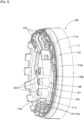
- the cluster block 120 is configured by an electrically insulating resin molded part comprising: a terminal accommodating portion 121 for accommodating the connection terminals 116; and a plurality of cylindrical terminal protectors 122 extending from the terminal accommodating portion 121 to the control housing 32 side.
- the terminal protectors 122 communicate with the inside of the terminal accommodating portion 121 and are inserted into through-holes 21d penetrating the bottom wall 21.
- the outer diameter of the terminal protectors 122 is smaller than the inner diameter of the through-holes 21d. As a result, a clearance is formed between the through-holes 21d and the terminal protectors 122.
- a sealed terminal 130 comprising a plurality of terminal pins 133 is connected to the cluster block 120.
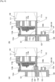
- the sealed terminal 130 comprises: a base plate 131 attachable to the bottom wall 21 from the outer wall surface 21a side; electrically insulating tubular insulating members 132 penetrating and fixed to the base plate 131; and conductive bar-shaped terminal pins 133 inserted through and fixed to the insulating member 132.
- the insulating members 132 are inserted into the terminal protectors 122 of the cluster block 120.
- the terminal pins 133 extend along the center line CL1 of the stator core 111 from inside the control housing 32 to inside the housing 20.
- the terminal pins 133 are detachably inserted into connecting portions 116a of the connection terminals 116, whereby the sealed terminal 130 can electrically connect the stator 103 and the control unit 140.
- the connecting portion 116a between the connection terminal 116 and the sealed terminal 130, i.e., the connecting portion 116a between the terminal pin 133 and the connection terminal 116, is covered by the cluster block 120.
- the sealed terminal 130 penetrates the bottom wall 21 of the housing 20 and is removably attached to the bottom wall 21 from the outer wall surface 21a side.
- control unit 140 is provided directly or indirectly on the outer wall surface 21a of the bottom wall 21 of the housing 20.
- control unit 140 is indirectly provided on the outer wall surface 21a of the bottom wall 21 of the housing 20 by removably accommodating the control unit 140 inside the control housing 32.
- control unit 140 is directly provided on the outer wall surface 21a of the bottom wall 21 of the housing 20 without the intermediary of the bottom wall 32a of the control housing 32.
- the control unit 140 comprises a board 142 on which control components 141 such as an inverter circuit are mounted, and a board-side connector 143 provided on the board 142.
- the board-side connector 143 is connectable to another end portion of each terminal pin 133.
- the control unit 140 is assembled inside the control housing 32, whereby the board-side connector 143 is connected to each terminal pin 133. As a result, the lead-out wires 115 are electrically connected to the control unit 140. Driving electrical power can be supplied from the control unit 140 to the motor 100.
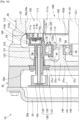
- the cluster block 120 is disposed in the space Sp between the bottom wall 21 and the first insulator 112 (the arrangement space Sp). Specifically, the cluster block 120 is positioned with a gap ga (clearance ga) from the bottom wall 21.
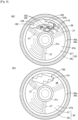
- the bearing holding portion 21c for holding the bearing 43 (second bearing 43), and a plurality of (e.g. three) reinforcing ribs 27 extending radially from the bearing holding portion 21c as far as the circumferential wall 22 of the housing 20 in order to reinforce the bottom wall 21 are integrally formed with the inner wall surface 21b of the bottom wall 21 of the housing 20.
- a space 28 surrounded by the inner wall surface 21b of the bottom wall 21, the circumferential wall 22, the bearing holding portion 21c, and two of the plurality of reinforcing ribs 27 is thus formed inside the housing 20. That is to say, the space 28 for receiving the cluster block 120 is formed in the inner wall surface 21b of the bottom wall 21.
- the space 28 may be referred to as the "cluster block receiving portion 28", as appropriate.
- the cluster block 120 is disposed in the cluster block receiving portion 28.
- the cluster block 120 can be very efficiently assembled by effectively utilizing the narrow space inside the housing 20, by providing the cluster block receiving portion 28 in the interior of the housing 20. It is therefore possible to achieve a reduction in the size of the electric compressor 10.
- the terminal accommodating portion 121 of the cluster block 120 has a bottom plate 123 facing the first insulator 112.
- a bottom surface 123a of the bottom plate 123 may be referred to as the "facing surface 123a facing the stator 103".
- At least one of the first support face 112d and the second support face 112e is positioned further to the facing surface 123a side of the cluster block 120 than axial end faces of the coil ends 114a of the coils 114.
- the length of the outer circumferential-side first edge portion 112b is greater than the length of the inner circumferential-side second edge portion 112c. Accordingly, the first support face 112d is positioned further to the facing surface 123a side of the cluster block 120 than the second support face 112e. Moreover, the first support face 112d is positioned further to the facing surface 123a side of the cluster block 120 than the axial end faces of the coil ends 114a.
- the cluster block 120 comprises a protrusion 124 protruding from the facing surface 123a toward the second support face 112e.
- the amount by which the protrusion 124 protrudes corresponds to a difference in a distance between the first support face 112d and the second support face 112e.
- the position of the first support face 112d and the position of the second support face 112e in relation to the facing surface 123a of the cluster block 120 are the same, and the first support face 112d and the second support face 112e are positioned further to the facing surface 123a side of the cluster block 120 than the axial end faces of the coil ends 114a.
- the cluster block 120 can be supported by the first support face 112d and the inner circumferential-side second support face 112e. In this case, the cluster block 120 does not comprise the protrusion 124.
- example 1 employs shrink fitting as the method for fixing the stator core 111 to the inner circumferential surface 20a (first inner circumferential surface 24a) of the housing 20.
- the cluster block 120 is disposed between the bottom wall 21 of the housing 20 and the first insulator 112. When the housing 20 is shrink fitted to the stator core 111, the cluster block 120 is therefore inserted into the housing 20 together with the stator 103. In this process, the cluster block 120 needs to be appropriately arranged so as not to contact the heated housing 20.
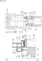
- the cluster block 120 is supported by means of a holding jig 150 during shrink fitting, as shown in fig. 2 , 4 and 8 .
- the cluster block 120 has a mating portion 125 enabling mating so that the cluster block 120 can be held by the holding jig 150.
- the cluster block 120 has the mating portion 125 capable of mating along the axis CL1 (center line CL1) of the rotor 102 with the holding jig 150 for holding the cluster block 120 in a state of being positioned with a gap ga (clearance ga) from the bottom wall 21.
- the mating portion 125 is formed on the bottom surface 123a (facing surface 123a) of the bottom plate 123 of the cluster block 120.
- the mating portion 125 can be mated with the holding jig 150 which is set on the stator 103 side.
- the cluster block 120 thus has the mating portion 125 enabling mating so that the cluster block 120 can be held by the holding jig 150 by means of a frictional force therebetween.
- the cluster block 120 in a state of being positioned with the gap ga (clearance ga) shown in fig. 2 from the bottom wall 21 of the housing 20 can therefore be held in an optimum state without inclination by means of the holding jig 150. Accordingly, the cluster block 120 can be appropriately arranged so as not to contact the housing 20.
- the structure for fixing the stator core 111 to the inner circumferential surface 20a of the housing 20 comprises fixing by means of an interference fit employing a shrink fit process
- the position of the cluster block 120 can be held by means of the holding jig 150 so that the cluster block 120 does not contact the heated housing 20.
- contact between the housing 20 and the cluster block 120 is avoided so that performance in terms of protecting the cluster block 120 can be improved.
- the mating configuration of the mating portion 125 with the holding jig 150 constitutes a "light press fit", which is a mating configuration capable of holding the mated state by means of a frictional force therebetween and also enabling detachment from each other by means of a detaching force.
- the cluster block 120 can therefore be stably held by means of the holding jig 150 in the space Sp between the bottom wall 21 and the stator core 111 while also being removable and accurately positionable.
- the cluster block 120 comprises the facing surface 123a facing the stator 103.
- the stator 103 comprises the insulator 112 (first insulator 112) which is provided on the end face 111a of the stator core 111 on the control unit 140 side and is sandwiched between the stator core 111 and the coils 114.
- the insulator 112 comprises the outer circumferential-side first support face 112d and the inner circumferential-side second support face 112e capable of supporting the facing surface 123a of the cluster block 120.
- the facing surface 123a of the cluster block 120 can therefore be supported (movement of the cluster block 120 can be restricted) by means of the first and second support faces 112d, 112e of the insulator 112 when the holding jig 150 (see fig. 4 ) is withdrawn from the mating portion 125 of the cluster block 120 after the stator core 103 has been assembled with (fixed to) the housing 20. It is therefore easy to withdraw the holding jig 150 from the cluster block 120.
- first and second support faces 112d, 112e are positioned further to the facing surface 123a side than the coil ends 114a of the coils 114.
- the cluster block 120 therefore does not touch the coil ends 114a when the holding jig 150 is withdrawn, so there are no concerns regarding damage to the coil ends 114a.
- the cluster block 120 is supported at the two locations of the outer circumferential-side first support face 112d and the inner circumferential-side second support face 112e, and the cluster block 120 can therefore be stably supported. Consequently, the cluster block 120 which is disposed toward the direction of the axis CL1 (center line CL1) of the rotor 102 can be stably supported by means of the insulator 112 so that the cluster block 120 does not contact the inner circumferential surface 20a (first inner circumferential surface 24a) of the heated housing 20.
- the cluster block 120 can be supported in the axial direction (the direction along the center line CL1 of the stator core 111) by means of the first and second support faces 112d, 112e when the terminal pin 133 of the sealed terminal 130 is inserted into the connection terminal 116 of the cluster block 120. Consequently, the sealed terminal 130 can be easily assembled with the connection terminal 116.
- the facing surface 123a of the cluster block 120 is brought close to the stator 103, as shown in fig. 2 . It is therefore not possible to ensure sufficient mating space between the mating portion 125 and the holding jig 150 (see fig. 4 ).
- the facing surface 123a of the cluster block 120 is positioned as far as radially inside the cylindrical stator core 111 (radially inward from the inner circumferential surface 111d of the stator core 111).
- the mating portion 125 is formed on a radially inside part 123b of the facing surface 123a (a part 123b radially inward from the inner circumferential surface 111d of the stator core 111).
- the mating portion 125 is preferably configured by at least one recessed mating recess 126 (a pair of mating recesses 126, 126 in the example).
- the mating recesses 126 open to the second insulator 113 side along the center line CL1 of the stator core 111, and are capable of mating with the holding jig 150.
- the radially inside part 123b may extend radially inward to the extent that there is no interference with the end face 102a of the rotor 102 shown in fig. 2 . It is therefore possible to ensure sufficient mating space between the mating portion 125 and the holding jig 150.
- the position and attitude of the cluster block 120 can be stably established by means of the holding jig 150, and very accurate positioning is possible as a result.
- the mating recesses 126, 126 are configured by a pair of arc-shaped grooves centered on the axis CL1 (center line CL1) of the rotor 102, and are positioned at a circumferential interval Ln1 from each other.
- the pair of mating recesses 126, 126 comprising a groove configuration may be configured by grooves of a pair of protrusions 127, 127 having a U-shaped cross section which protrude from the facing surface 123a of the cluster block 120.
- the pair of protrusions 127, 127 are arranged so that openings of the U-shaped cross sections face in opposite directions.
- the mating recesses 126, 126 are configured by the grooves of the protrusions 127, 127, and the depths of the groove-shaped mating recesses 126, 126 can therefore be freely set without being restricted by the thickness of the bottom plate 123.
- the holding jig 150 which has the function of a jig for supporting the stator 103, comprises: a cylindrical jig base portion 151 capable of mating with the inner circumferential surface 11 1d of the stator core 111; and a cylindrical block holding portion 152 extending from a tip end face 151a of the jig base portion 151 to the cluster block 120 side.
- the block holding portion 152 has a cutout 153 where a portion has been cut out in the circumferential direction.
- An interval Ln2 between edges 153a, 153a on both circumferential sides which form the cutout 153 is the same as the interval Ln1 between the groove-shaped mating recesses 126, 126.
- the mating recesses 126, 126 of the cluster block 120 mate with tip end parts of the block holding portion 152 of the holding jig 150.
- Ends 126a, 126a of the mating recesses 126, 126 fit together with the edges 153a, 153a on both circumferential sides of the cutout 153, whereby the circumferential position of the cluster block 120 in relation to the block holding portion 152 is established. That is to say, the relative position of the cluster block 120 with respect to the block holding portion 152 can be established while misalignment therebetween can also be controlled.
- the groove-shaped mating recesses 126, 126 are mated with the holding jig 150 whereby it is possible to restrict relative movement of the cluster block 120 with respect to the holding jig 150 in both the direction orthogonal to the axis CL1 of the rotor 102 and the rotation direction about the axis CL1 of the rotor 102.
- the cluster block 120 can therefore be positioned very accurately in relation to the holding jig 150.
- a positioning bar 154 more preferably extends from the holding jig 150 toward the cluster block 120.
- the positioning bar 154 positions a side face of the terminal accommodating portion 121 of the cluster block 120 so that the cluster block 120 can be positioned even more accurately in relation to the holding jig 150.
- mating grooves 126, 126 of the cluster block 120 may also have a configuration which is indented from the facing surface 123a of the cluster block 120, for example.
- a summary description of the electric compressor 10 relating to the assembly method of this example 1 is as follows.
- the electric compressor 10 comprises:
- the cluster block 120 comprises a mating portion 125 capable of mating along an axis CL1 of the rotor 102 with a holding jig 150 (see fig. 4 ) for holding the cluster block 120.
- the method for fixing the stator core 111 to the housing 20 by means of shrink fitting is carried out by means of at least the following preparation step, holding step, fitting step, fixing step, and detachment step.
- a step (preparation step) in which the stator 103 comprising the cluster block 120 is prepared is carried out first of all.
- the cluster block 120 is connected to the coils 114 by means of the lead-out wires 115 (see fig. 4 ).
- a step (holding step) is carried out, in which the holding jig 150 is inserted into the mating portion 125 of the cluster block 120 so that the cluster block 120 is positioned with a gap ga from the bottom wall 21 of the housing 20, as in fig. 2 , and the cluster block 120 is held by the holding jig 150 (see fig. 10(a) ).
- the stator 103 is first of all fitted to the holding jig 150.
- the stator core 111 is positioned and set in relation to the jig base portion 151 of the holding jig 150.
- the mating portion 125 (mating grooves 126) of the cluster block 120 are mated with the tip end parts of the block holding portion 152.
- the cluster block 120 is positioned on the holding jig 150.
- the facing surface 123a of the cluster block 120 is supported by means of the support faces 112d, 112e of the first insulator 112.
- a step (fitting step) is carried out, in which the housing 20 in a state of having been thermally expanded by means of heating is fitted to the stator 103 in a state in which the cluster block 120 is held by means of the holding jig 150.
- the relative positions of the housing 20 and a heater 161 are set with respect to the holding jig 150, and the housing 20 and the heater 161 can be moved along the center line CL1 of the stator core 111.
- the heater 161 first of all heats the area around the first accommodating chamber 24 of the housing 20 under preset heating conditions.
- the housing 20 which has been heated up to a predetermined heating temperature is then fitted to the outer circumferential surface of the stator core 111.
- the fitting step as shown in fig. 11(a) , the housing 20 is fitted to the stator core 111.
- a step (fixing step) is carried out, in which the housing 20 is returned to normal temperature and thereby contracted so that the stator core 111 is fixed to the housing 20.
- the heater 161 is first of all removed from the housing 20.
- the housing 20 is then returned to normal temperature by means of cooling such as air cooling (including natural cooling).
- the housing 20 is shrink fitted to the stator core 111.
- normal temperature includes a normal temperature of 20°C ⁇ 15°C defined in Japanese Industrial Standards (JIS Z 8703), but normal temperature is not necessarily limited to this provided that the temperature is suitable for shrink fitting the housing 20 to the stator core 111.
- a step (detachment step) is carried out, in which the holding jig 150 is detached from the mating portion 125 of the cluster block 120.
- the housing 20 is pulled up from the holding jig 150.
- the mating grooves 126, 126 of the cluster block 120 are withdrawn from the tip end parts of the block holding portion 152.
- the facing surface 123a of the cluster block 120 is supported by means of the support faces 112d, 112e of the first insulator 112, and the mating grooves 126, 126 of the cluster block 120 are therefore easy to withdraw from the tip end parts of the block holding portion 152.
- a step (terminal assembly step) is carried out, in which the sealed terminal 130 (see fig. 4 ) is assembled with the cluster block 120, completing the assembly method.
- An example of the terminal assembly step is as follows. As a result of carrying out the fixing step above, the terminal protectors 122 are inserted with a gap into the through-holes 21d in the bottom wall 21 of the housing 20. As shown in fig. 4 , the sealed terminal 130 is inserted into the through-hole 21d from the outer wall surface 21a side of the bottom wall 21 and introduced into the connecting portion 116a inside the cluster block 120. The sealed terminal 130 can be assembled with the cluster block 120 as a result.
- the cluster block 120 can be supported in the axial direction (the direction along the center line CL1 of the stator core 111) by means of the first and second support faces 112d, 112e when the sealed terminal 130 is inserted into the connection terminal 116 of the cluster block 120. Consequently, the sealed terminal 130 can be easily assembled with the connection terminal 116.
- the terminal assembly step should be carried out after the fixing step shown in fig. 11(a) .
- the terminal assembly step is carried out between the fixing step shown in fig. 11(a) and the detachment step shown in fig. 11(b) .
- the cluster block 120 is in a state of being positioned by the holding jig 150.
- the sealed terminal 130 can therefore be assembled with the cluster block 120 even more easily.
- the bottom surface of the mating recesses 126 (bottom surface 123a of the bottom plate 123) abuts the tip end face of the block holding portion 152, thereby determining the height of the cluster block 120 in relation to the tip end face 151a of the holding jig 150.
- the position of the stator core 111 in relation to the holding jig 150 in the center line CL1 direction is managed, as shown in fig. 10(b) .
- the position of the housing 20 in relation to the holding jig 150 in the center line CL1 direction is managed, as shown in fig. 11(a) . Accordingly, the gap ga between the cluster block 120 and the bottom wall 21 of the housing 20 shown in fig. 2 is necessarily determined and can be managed with sufficiently good accuracy.
- the cluster block 120 has the mating portion 125 enabling mating so that the cluster block 120 can be held by the holding jig 150.
- the cluster block 120 in a state of being positioned with the gap ga (clearance ga) from the bottom wall 21 of the housing 20 can therefore be held in an optimum state by means of the holding jig 150 without inclination. Accordingly, when the stator core 111 is fixed to the heated housing 20 by means of shrink fitting, the cluster block 120 can be appropriately arranged so as not to contact the heated housing 20. Performance in terms of protecting the cluster block 120 can be improved as a result.
- the mating portion 125 of the cluster block 120 is mated to an extent that the holding jig 150 can be detached from the mating portion 125.
- Mating of the mating portion 125 with the holding jig 150 can thus be afforded by a "light press fit", which is mating capable of holding the mated state and also enabling detachment from each other by means of a detaching force.
- the cluster block 120 can therefore be stably held by means of the holding jig 150 in the space Sp between the bottom wall 21 and the first insulator 112 while also being removable and accurately positionable.
- An electric compressor 200 according to example 2 will be described with reference to fig. 12-13 .
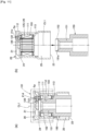
- Fig. 12 is an exploded diagram showing a relationship of a holding jig 250 and a cluster block 220 of the electric compressor 200 according to example 2, corresponding to fig. 8 illustrating the relationship of the holding jig 150 and the cluster block 120 of example 1 described above.
- Fig. 13(a) is an exploded diagram illustrating a relationship of a mating portion 225 and the holding jig 250 shown in fig. 12 .
- Fig. 13(b) is a view in cross section illustrating a mated state of the mating portion 225 and the holding jig 250 shown in fig. 13(a) .
- the cluster block 220 of the electric compressor 200 according to example 2 is characterized by comprising a mating portion 225 capable of mating along the axis CL1 of the rotor 102 (see fig. 2 ) with a holding jig 250 for holding the cluster block 220.
- the mating portion 225 corresponds to the mating portion 125 of example 1 shown in fig. 8 .
- the holding jig 250 corresponds to the holding jig 150 of example 1 shown in fig. 8 .
- the mating portion 225 is configured by recessed mating recesses 226, 227 formed on the radially inside part 123b (see fig. 6(a) ) of the facing surface 123a of the cluster block 220.
- the mating recesses 226, 227 open to the second insulator 113 side (see fig. 1 ) along the center line CL1 of the rotor 102 (see fig. 2 ), and are capable of mating with the holding jig 250.
- the mating recesses 226, 227 are positioned at an interval Ln3 from each other.
- the mating recesses 226, 227 are configured by a pair of holes which correspond to the mating recesses 126, 126 of example 1 shown in fig. 8 .
- the pair of mating recesses 226, 227 comprising a round hole-shaped configuration may be configured, for example, by bottomed annular holes of a pair of protrusions 228, 229 which protrude from the facing surface 123a of the cluster block 220.
- the recesses 226, 227 are configured by the holes of the protrusions 228, 229, and the depths of the mating recesses 226, 227 can therefore be freely set without being restricted by the thickness of the bottom plate 123.
- the pair of mating recesses 226, 227 are accommodated by the pair of protrusions 228, 229, whereby the relative position of the cluster block 220 with respect to the holding jig 250 can be established while misalignment therebetween can also be controlled.
- the holding jig 250 which has the function of a jig for supporting the stator 103, comprises: the same jig base portion 151 as in example 1; and bar-shaped (e.g., round bar-shaped, columnar or tubular) block holding portions 252, 253 extending from the tip end face 151a of the jig base portion 151 to the cluster block 220 side.
- the interval Ln3 between between the block holding portions 252, 253 is the same as the interval Ln3 between the hole-shaped mating recesses 226, 227.
- the mating recesses 226, 227 of the cluster block 220 thus mate with the block holding portions 252, 253 of the holding jig 250.
- the hole-shaped mating recesses 226, 227 are mated with the holding jig 250 whereby it is possible to restrict relative movement of the cluster block 220 with respect to the holding jig 250 in both the direction orthogonal to the axis CL1 of the rotor 102 and the rotation direction about the axis CL1 of the rotor 102.
- the cluster block 220 can therefore be positioned very accurately in relation to the holding jig 250.
- mating recesses 226, 227 (mating holes 226, 227) of the cluster block 220 may have a configuration which is indented from the facing surface 123a of the cluster block 220, for example.
- Mating of the mating portion 225 with the holding jig 250 constitutes a "light press fit", which is mating capable of holding the mated state by means of a frictional force therebetween and also enabling detachment from each other by means of a detaching force.
- either one of the pair of mating recesses 226, 227 serves as a first mating recess 226, with the other serving as a second mating recess 227.
- Either one of the pair of block holding portions 252, 253 serves as a first block holding portion 252, with the other serving as a second block holding portion 253.
- the mating configuration of the first mating recess 226 and the first block holding portion 252 is referred to as a first mating configuration.
- the mating configuration of the second mating recess 227 and the second block holding portion 253 is referred to as a second mating configuration.
- the pair of mating recesses 226, 227 have the same diameter, and the pair of block holding portions 252, 253 also have the same diameter. It should be noted that this is not limiting.
- either one of the first mating configuration and the second mating configuration is a light press fit configuration, with the other being a clearance fit configuration.
- this can be achieved by making a mating tolerance of the first mating different from a mating tolerance of the second mating.
- the light press fit configuration may be achieved by interposing an elastic member 254 in either one of the first mating configuration and the second mating configuration.
- a clearance fit configuration is used for mating of the first mating recess 226 and the first block holding portion 252.
- a configuration with an annular elastic member 254 such as an O-ring interposed is used for mating of the second mating recess 227 and the second block holding portion 253.
- the elastic member 254 is fitted in a groove 253a provided on an outer circumferential surface of the second block holding portion 253.
- both the first mating configuration and the second mating configuration are light press fit configurations.
- this can be achieved by making the mating tolerance of the first mating the same as the mating tolerance of the second mating.
- the first mating configuration can be made the same as the second mating configuration of the first example in which the elastic member 254 is interposed.
- both the first mating configuration and the second mating configuration are light press fit configurations.
- the housing 20 may be configured so that only the motor 100 is housed therein, without the compression mechanism 50 being housed therein.
- the compression mechanism 50 is not limited to a scroll compression mechanism configuration, provided that the compression mechanism 50 is driven by means of the motor 100 in order to compress a gas (e.g., a gaseous refrigerant).
- a gas e.g., a gaseous refrigerant
- the electric compressors 10, 200 according to the present invention are suitable for use in a refrigeration cycle of a vehicle air conditioning device.
Landscapes
- Engineering & Computer Science (AREA)
- Mechanical Engineering (AREA)
- General Engineering & Computer Science (AREA)
- Power Engineering (AREA)
- Compressor (AREA)
Applications Claiming Priority (2)
| Application Number | Priority Date | Filing Date | Title |
|---|---|---|---|
| JP2022052910 | 2022-03-29 | ||
| PCT/JP2023/011102 WO2023189893A1 (fr) | 2022-03-29 | 2023-03-22 | Compresseur électrique et procédé d'assemblage de compresseur électrique |
Publications (2)
| Publication Number | Publication Date |
|---|---|
| EP4502379A1 true EP4502379A1 (fr) | 2025-02-05 |
| EP4502379A4 EP4502379A4 (fr) | 2026-03-11 |
Family
ID=88201192
Family Applications (1)
| Application Number | Title | Priority Date | Filing Date |
|---|---|---|---|
| EP23779907.7A Pending EP4502379A4 (fr) | 2022-03-29 | 2023-03-22 | Compresseur électrique et procédé d'assemblage de compresseur électrique |
Country Status (4)
| Country | Link |
|---|---|
| EP (1) | EP4502379A4 (fr) |
| JP (1) | JPWO2023189893A1 (fr) |
| CN (1) | CN119013472A (fr) |
| WO (1) | WO2023189893A1 (fr) |
Family Cites Families (4)
| Publication number | Priority date | Publication date | Assignee | Title |
|---|---|---|---|---|
| JP2015195691A (ja) * | 2014-03-31 | 2015-11-05 | ダイキン工業株式会社 | モータおよび圧縮機 |
| WO2017163539A1 (fr) * | 2016-03-23 | 2017-09-28 | 株式会社 豊田自動織機 | Machine à fluide à entraînement électrique |
| JP2019152194A (ja) * | 2018-03-06 | 2019-09-12 | 株式会社豊田自動織機 | 電動圧縮機 |
| JP7263902B2 (ja) * | 2019-04-25 | 2023-04-25 | 株式会社豊田自動織機 | 電動圧縮機及び電動圧縮機の組立方法 |
-
2023
- 2023-03-22 EP EP23779907.7A patent/EP4502379A4/fr active Pending
- 2023-03-22 JP JP2024511929A patent/JPWO2023189893A1/ja active Pending
- 2023-03-22 CN CN202380031421.8A patent/CN119013472A/zh active Pending
- 2023-03-22 WO PCT/JP2023/011102 patent/WO2023189893A1/fr not_active Ceased
Also Published As
| Publication number | Publication date |
|---|---|
| EP4502379A4 (fr) | 2026-03-11 |
| WO2023189893A1 (fr) | 2023-10-05 |
| JPWO2023189893A1 (fr) | 2023-10-05 |
| CN119013472A (zh) | 2024-11-22 |
Similar Documents
| Publication | Publication Date | Title |
|---|---|---|
| JP5669586B2 (ja) | 圧縮機用モータおよびそれを用いた電動圧縮機 | |
| JP6507270B2 (ja) | 圧縮機 | |
| KR101042160B1 (ko) | 전동 컴프레서 | |
| CN113464436B (zh) | 电动压缩机 | |
| CN104364525B (zh) | 电动压缩机 | |
| US20060119196A1 (en) | Supporting structure for cooling jacket of motor/generator | |
| EP2050959A2 (fr) | Procédé de fabrication de compresseur électrique et compresseur électrique | |
| CN108291540A (zh) | 具有电连接机构的电动压缩机及用于其的定子组装体 | |
| EP2620648A2 (fr) | Compresseur entraîné par moteur et son procédé de fabrication | |
| US20250067261A1 (en) | Motor-driven compressor | |
| KR101573970B1 (ko) | 전동 압축기 | |
| EP3748165A1 (fr) | Compresseur motorisé | |
| EP4502379A1 (fr) | Compresseur électrique et procédé d'assemblage de compresseur électrique | |
| CN119343521A (zh) | 电动压缩机 | |
| JP2020070732A (ja) | 電動圧縮機 | |
| JP2016217291A (ja) | 電動コンプレッサ及びその製造方法 | |
| CN116601388B (zh) | 车辆用电动压缩机 | |
| JPH08219060A (ja) | 密閉型圧縮機 | |
| WO2024084914A1 (fr) | Compresseur électrique | |
| KR101893853B1 (ko) | 전동 압축기 | |
| WO2023248707A1 (fr) | Compresseur électrique et son procédé de fabrication | |
| JPH08109885A (ja) | スクロール型圧縮機の組立方法及び組立治具 | |
| CN121356213A (zh) | 线束块固定结构、电动机、电动压缩机、空调装置、冰箱以及车载装置 | |
| CN121285927A (zh) | 马达定子及具备该马达定子的电动压缩机 | |
| KR101927254B1 (ko) | 전동 압축기 |
Legal Events
| Date | Code | Title | Description |
|---|---|---|---|
| STAA | Information on the status of an ep patent application or granted ep patent |
Free format text: STATUS: THE INTERNATIONAL PUBLICATION HAS BEEN MADE |
|
| PUAI | Public reference made under article 153(3) epc to a published international application that has entered the european phase |
Free format text: ORIGINAL CODE: 0009012 |
|
| STAA | Information on the status of an ep patent application or granted ep patent |
Free format text: STATUS: REQUEST FOR EXAMINATION WAS MADE |
|
| 17P | Request for examination filed |
Effective date: 20240926 |
|
| AK | Designated contracting states |
Kind code of ref document: A1 Designated state(s): AL AT BE BG CH CY CZ DE DK EE ES FI FR GB GR HR HU IE IS IT LI LT LU LV MC ME MK MT NL NO PL PT RO RS SE SI SK SM TR |
|
| DAV | Request for validation of the european patent (deleted) | ||
| DAX | Request for extension of the european patent (deleted) | ||
| A4 | Supplementary search report drawn up and despatched |
Effective date: 20260209 |
|
| RIC1 | Information provided on ipc code assigned before grant |
Ipc: F04B 39/00 20060101AFI20260203BHEP Ipc: F04C 29/00 20060101ALI20260203BHEP Ipc: H02K 3/46 20060101ALI20260203BHEP Ipc: H02K 3/50 20060101ALI20260203BHEP Ipc: H02K 3/52 20060101ALI20260203BHEP Ipc: F04B 35/04 20060101ALI20260203BHEP Ipc: F04B 39/12 20060101ALI20260203BHEP Ipc: F04C 18/02 20060101ALI20260203BHEP Ipc: F04C 23/00 20060101ALI20260203BHEP Ipc: H02K 5/15 20060101ALN20260203BHEP Ipc: H02K 5/173 20060101ALN20260203BHEP |
|
| RAP1 | Party data changed (applicant data changed or rights of an application transferred) |
Owner name: VALEO ELECTRIFICATION |