EP4502632A1 - Batterieverwaltungsvorrichtung und -verfahren - Google Patents
Batterieverwaltungsvorrichtung und -verfahren Download PDFInfo
- Publication number
- EP4502632A1 EP4502632A1 EP22936645.5A EP22936645A EP4502632A1 EP 4502632 A1 EP4502632 A1 EP 4502632A1 EP 22936645 A EP22936645 A EP 22936645A EP 4502632 A1 EP4502632 A1 EP 4502632A1
- Authority
- EP
- European Patent Office
- Prior art keywords
- battery
- controller
- data
- score
- management apparatus
- Prior art date
- Legal status (The legal status is an assumption and is not a legal conclusion. Google has not performed a legal analysis and makes no representation as to the accuracy of the status listed.)
- Pending
Links
Images




Classifications
-
- G—PHYSICS
- G01—MEASURING; TESTING
- G01R—MEASURING ELECTRIC VARIABLES; MEASURING MAGNETIC VARIABLES
- G01R31/00—Arrangements for testing electric properties; Arrangements for locating electric faults; Arrangements for electrical testing characterised by what is being tested not provided for elsewhere
- G01R31/36—Arrangements for testing, measuring or monitoring the electrical condition of accumulators or electric batteries, e.g. capacity or state of charge [SoC]
- G01R31/367—Software therefor, e.g. for battery testing using modelling or look-up tables
-
- G—PHYSICS
- G01—MEASURING; TESTING
- G01R—MEASURING ELECTRIC VARIABLES; MEASURING MAGNETIC VARIABLES
- G01R31/00—Arrangements for testing electric properties; Arrangements for locating electric faults; Arrangements for electrical testing characterised by what is being tested not provided for elsewhere
- G01R31/36—Arrangements for testing, measuring or monitoring the electrical condition of accumulators or electric batteries, e.g. capacity or state of charge [SoC]
-
- G—PHYSICS
- G01—MEASURING; TESTING
- G01R—MEASURING ELECTRIC VARIABLES; MEASURING MAGNETIC VARIABLES
- G01R31/00—Arrangements for testing electric properties; Arrangements for locating electric faults; Arrangements for electrical testing characterised by what is being tested not provided for elsewhere
- G01R31/36—Arrangements for testing, measuring or monitoring the electrical condition of accumulators or electric batteries, e.g. capacity or state of charge [SoC]
- G01R31/3644—Constructional arrangements
- G01R31/3648—Constructional arrangements comprising digital calculation means, e.g. for performing an algorithm
-
- G—PHYSICS
- G01—MEASURING; TESTING
- G01R—MEASURING ELECTRIC VARIABLES; MEASURING MAGNETIC VARIABLES
- G01R31/00—Arrangements for testing electric properties; Arrangements for locating electric faults; Arrangements for electrical testing characterised by what is being tested not provided for elsewhere
- G01R31/36—Arrangements for testing, measuring or monitoring the electrical condition of accumulators or electric batteries, e.g. capacity or state of charge [SoC]
- G01R31/382—Arrangements for monitoring battery or accumulator variables, e.g. SoC
-
- G—PHYSICS
- G01—MEASURING; TESTING
- G01R—MEASURING ELECTRIC VARIABLES; MEASURING MAGNETIC VARIABLES
- G01R31/00—Arrangements for testing electric properties; Arrangements for locating electric faults; Arrangements for electrical testing characterised by what is being tested not provided for elsewhere
- G01R31/36—Arrangements for testing, measuring or monitoring the electrical condition of accumulators or electric batteries, e.g. capacity or state of charge [SoC]
- G01R31/392—Determining battery ageing or deterioration, e.g. state of health
-
- Y—GENERAL TAGGING OF NEW TECHNOLOGICAL DEVELOPMENTS; GENERAL TAGGING OF CROSS-SECTIONAL TECHNOLOGIES SPANNING OVER SEVERAL SECTIONS OF THE IPC; TECHNICAL SUBJECTS COVERED BY FORMER USPC CROSS-REFERENCE ART COLLECTIONS [XRACs] AND DIGESTS
- Y02—TECHNOLOGIES OR APPLICATIONS FOR MITIGATION OR ADAPTATION AGAINST CLIMATE CHANGE
- Y02E—REDUCTION OF GREENHOUSE GAS [GHG] EMISSIONS, RELATED TO ENERGY GENERATION, TRANSMISSION OR DISTRIBUTION
- Y02E60/00—Enabling technologies; Technologies with a potential or indirect contribution to GHG emissions mitigation
- Y02E60/10—Energy storage using batteries
Definitions
- the present disclosure relates to a battery management apparatus and method.
- the present disclosure has been made to solve such a problem and aims to score lifetime and safety of a battery and provide them to a user.
- a battery management apparatus includes a data obtaining unit configured to obtain battery information of at least one of voltage, current, and temperature and a controller configured to determine a data distribution of the battery based on the obtained battery information, determine a matching probability between a plurality of previously obtained target experiment data and the data distribution, determine a score for each of the plurality of target experiment data based on the battery information, and calculate the matching probability corresponding to the score for each of the plurality of target experiment data to calculate a stress score for the battery.
- the controller may be further configured to determine a type based on whether the obtained battery information is during-driving information or during-charge information and determine the plurality of target experiment data corresponding to the determined type from among a plurality of previously stored experiment data.
- the controller may be further configured to determine the data distribution of the battery by calculating an area-specific frequency for the battery information.
- the controller may be further configured to determine the matching probability for each of the plurality of target experiment data based on the area-specific frequency for the battery information and an area-specific frequency for each of the plurality of target experiment data.
- the controller may be further configured to determine the matching probability based on a similarity between a frequency of each target experiment data and the area-specific frequency for the battery information with respect to a sum of area-specific frequencies of the plurality of target experiment data for each area.
- the controller may be further configured to sum one or more similarities calculated respectively for the plurality of target experiment data to determine the matching probability corresponding to each of the plurality of target experiment data.
- the controller may be further configured to determine the score based on a preset experiment condition-specific table for each of the plurality of target experiment data.
- the experiment condition-specific table may be preset for experiment conditions including at least one of an experiment temperature, a charge current, a discharge current, a maximum (SOC) and a minimum SOC, and an (SOH) corresponding to a number of times of charge/discharge of the target experiment data, and the controller may be further configured to determine the score for a number of times of charge/discharge in which a calculated SOH reaches a threshold value.
- the controller may be further configured to generate a response message including the stress score and output the generated response message, when receiving a request message for the stress score.
- the controller may be further configured to further include at least one of a driving guide and a charge guide corresponding to the stress score in the response message.
- a battery pack according to an aspect of the present disclosure includes the battery management apparatus according to the aspect of the present disclosure.
- a server according to an aspect of the present disclosure includes the battery management apparatus according to the aspect of the present disclosure.
- a battery management method includes obtaining battery information of at least one of voltage, current, and temperature, determining a data distribution of a battery based on the obtained battery information, determining a matching probability between a plurality of previously obtained target experiment data and the data distribution, determining a score for each of the plurality of target experiment data based on the battery information, and calculating a stress score for the battery by calculating the score for each of the plurality of target experiment data and the corresponding matching probability.
- lifetime and safety of a battery may be scored and provided to a user.
- advanced techniques such as normalization and/or a statistical variable threshold, etc., may be applied to accurately diagnose the lifetime and safety of the battery.
- FIG. 1 is a view of a battery system 1 according to an embodiment disclosed herein.
- the battery system 1 may include a battery management apparatus 100.
- this is only a preferred embodiment for achieving the object of the present disclosure, and some components may be added or removed as needed.
- respective components of the battery system 1 shown in FIG. 1 represent functionally distinguished functional elements, and a plurality of components may be implemented in a form integrated with each other in an actual physical environment.
- the battery management apparatus 100 may be a computing device that provides battery management based on stress scores to multiple users.
- the computing device may be a laptop, a desktop, a laptop, etc., without being limited thereto, and may include any type of devices including a computing function and a communication function.
- the battery management apparatus 100 may be preferably implemented as a high-performance server computing device.
- battery management may mean a service provided to a user for lifetime improvement of the battery based on a stress score.
- the stress score may refer to a score of effects of an experience and an environment occurring in a charge/discharge situation of a battery included in a vehicle (e.g., a vehicle driving situation and/or a battery charging situation) on the lifetime of the battery.
- a battery cell may include a negative terminal and a positive terminal and mean one independent cell that is physically separable.
- a lithium ion battery or a lithium polymer battery may be regarded as a battery cell.
- a plurality of battery cells may be connected in series and/or in parallel to constitute a battery module, and a plurality of battery modules may be connected in series and/or in parallel to constitute a battery pack.
- a battery for which a stress score may be calculated and provided by the battery management apparatus 100 may be a battery pack included in a vehicle.
- the battery management apparatus 100 may receive battery information from a battery management system (BMS) 50 and calculate a stress score for the battery based on the battery information.
- the battery information may mean data including information of at least one of voltage, current, and temperature of the battery.
- the battery management apparatus 100 may calculate a stress score based on a plurality of target experiment data previously obtained.
- the BMS 50 may lithium-ion be included in the vehicle and transmit information related to the battery included in the battery. More specifically, the BMS 50 may transmit information of at least one of the voltage, the current, and/or the temperature of the battery to the battery management apparatus 100. According to an embodiment, the BMS 50 may transmit information in real time to the battery management apparatus 100, and transmit the information to the battery management apparatus 100 at specific time intervals, without being limited thereto.
- the BMS 50 may be set up on a computing device that is physically independent of the battery management apparatus 100, or may be set up on the battery management apparatus 100, which may vary with an embodiment.
- the battery management apparatus 100 may be applied to a BMS. That is, the BMS according to the present disclosure may include the above-described battery management apparatus 100. With this configuration, at least some of components of the battery management apparatus 100 may be implemented by supplementing or adding functions of components included in a conventional BMS. For example, a data obtaining unit 110 and/or a controller 120 of the battery management apparatus 100 described below may be implemented as components of the BMS.
- a user terminal 30 may be a computing device that transmits a request for a stress score and includes a display for outputting response data including the stress score.
- the computing device may be a laptop, a desktop, a laptop, etc., without being limited thereto, and may include any type of devices including a computing function and a communication function.
- the user terminal 30 may be set up on a computing device that is physically independent of the battery management apparatus 100, or may be set up on the battery management apparatus 100, which may vary with an embodiment.
- a description will continue assuming that the user terminal 30 is set up on a computing device that is physically independent of the battery management apparatus 100.
- the user terminal 30 may display response data in which the stress score is imaged.
- the battery management apparatus 100 may receive the request for the stress score through a user's terminal and provide the response data including the stress score in response to the received request.
- the battery management apparatus 100 may provide a predetermined user interface to the response data to induce a user feedback, and the user may provide user feedback information for a satisfaction with the response data through the interface.
- the battery management apparatus 100 may reflect the user feedback information to improve the satisfaction of the user in calculation of the stress score.
- Components of the battery system 1 may communicate through a network.
- the network may be implemented in any type of wired/wireless networks such as a local area network (LAN), a wide area network (WAN), a mobile radio communication network, and Wireless Broadband Internet (Wibro) , etc.
- LAN local area network
- WAN wide area network
- Wibro Wireless Broadband Internet
- the battery system 1 according to an embodiment of the present disclosure has been described with reference to FIG. 1 .
- a configuration and an operation of the battery management apparatus 100 according to an embodiment of the present disclosure will be described with reference to FIGS. 2 to 6 .
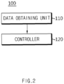
- FIG. 2 is a block diagram of the battery management apparatus 100 according to an embodiment disclosed herein.
- the battery management apparatus 100 may include the information obtaining unit 110 and the controller 120.
- the data obtaining unit 110 may be configured to obtain battery information of at least one of voltage, current, and temperature.
- the data obtaining unit 110 may obtain information related to a battery for which a stress score is to be calculated.
- the data obtaining unit 110 may obtain, from the BMS 50, the information related to the battery for which a stress score is to be calculated.
- the information related to the battery may include information related to at least one of voltage, current, and temperature of the battery.
- the data obtaining unit 110 may obtain information about the battery from the BMS 50 in real time or according to a predetermined period. Alternatively, the data obtaining unit 110 may obtain the information about the battery from the BMS 50 in case of occurrence of a preset event. The present disclosure is not limited thereto.
- the data obtaining unit 110 may transmit a request for providing data to the BMS 50.
- the controller 120 may determine a data distribution of the battery based on obtained battery information.
- the controller 120 may determine the data distribution of the battery by calculating an area-specific frequency for the battery information.
- the area-specific frequency may mean an area-specific frequency regarding each battery information.
- the controller 120 may divide an area of a battery voltage by predetermined unit (e.g., 0.1 V) in a preset voltage section, and calculate an area-specific frequency to which the battery information belongs in each area.
- the controller 120 may determine the data distribution of the battery based on the calculated area-specific frequency.
- the controller 120 may be configured to determine a matching probability between a plurality of previously obtained target experiment data and a data distribution.
- the controller 120 may determine the match probability for each of the plurality of target experiment data, based on the area-specific frequency of the battery information and the area-specific frequency of each of the plurality of target experiment data. This will be described in detail with reference to FIG. 3 .
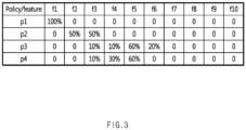
- FIG. 3 is a view for describing a method for determining a matching probability referred in various embodiments disclosed herein.
- FIG. 3 shows a table in which a frequency for each area (f1 to f10) for each of a plurality of target experiment data p1 to p4 is shown.
- f1 to f10 may mean areas into which the entire area (0 % to 100 %) is proportionally divided by 10 %.
- f1 may be an area of 0 % or more and below 10 % with respect to the entire area
- f2 may be an area of 10 % or more and below 20 % with respect to the entire area
- f10 may be an area of 90 % or more and 100 % or less with respect to the entire area.
- the area-specific frequency for the battery information is 10 % for f1, 30 % for f2, and 60 % for f3.
- the controller 120 may determine the matching probability for each of the plurality of target experiment data p1 to p4 by using the area-specific frequency for the battery information.
- the area-specific frequency for p1 is 100 % and is 0 % for the other areas.
- the area-specific frequency for p2 is 0 % and is 50 %, respectively, for f2 and f3.
- the controller 120 may determine, for each area, a similarity between a frequency of each target experiment data with respect to a sum of frequencies of a plurality of target experiment data, and a frequency for battery information, and determine a matching probability based on the similarity.
- the controller 120 may determine a similarity of p1 for f1 by multiplying the frequency for the battery information by "(a frequency of p1 for f1) ⁇ (a sum of frequencies of p1 to p4 for f1)".
- the sum of the frequencies of the plurality of target experiment data for f1 is 100 + 0 + 0 + 0 and thus is 100, and the frequency of p1 for f1 is 100.
- the frequency for the battery information is assumed to be 10 %, such that the controller 120 may determine a product of 10 % and (100 ⁇ 100) as the similarity of p1 for f1.
- the controller 120 may determine the similarity of p1 for f1 as 10 % or 0.1.
- the controller 120 may determine similarities of p2 to p4 for f1. Referring to FIG. 3 , as the frequencies of p2 to p4 for f1 are 0, the controller 120 may determine the similarities of p2 to p4 for f1 to be 0.
- the controller 120 may sum one or more similarities calculated respectively for the plurality of target experiment data to determine the matching probability corresponding to each of the plurality of target experiment data.
- the controller 120 may determine a similarity for f1 to be 0.1, and determine similarities for the other areas f2 to f10 as the frequency of p1 for the other areas f2 to f10 is 0.
- the controller 120 may determine 0.1 as a matching probability of p1.
- the controller 120 may determine matching probabilities of p2 to p4. Referring to FIG. 3 , the controller 120 may determine the matching probabilities of p2 to p4 to be 0.72, 0.09, and 0.09, respectively.
- the controller 120 may determine a score for each of the plurality of target experiment data based on the obtained data information.
- the controller 120 may determine a score for each of the plurality of target experiment data based on a preset experiment condition-specific table.
- the preset experiment condition-specific table may mean a table regarding result data of a battery deterioration experiment performed in an environment limited by a specific condition.
- the experiment condition-specific table may mean a table regarding data of a battery deterioration experiment performed by adding a condition to at least one area among a temperature, a charge current, a discharge current, a minimum SOC, and a maximum SOC of a battery and a SOH with respect to the number times of charge/discharge of the target experiment data. This will be described in detail with reference to FIG. 4 .
- FIG. 4 is a view for describing a method for determining a score for each of a plurality of target experiment data referred in various embodiments disclosed herein.
- FIG. 4 is shown an example diagram where the table is converted into an experiment condition-specific table by using the data obtained from the battery deterioration experiment performed in the limited environment.
- the controller 120 may generate a (SOH) profile according to a cycle by processing data obtained by a battery deterioration experiment performed in the limited environment.
- the cycle may mean a value obtained by considering charge/discharge of the battery as one period.
- 1 cycle may mean that the battery is charged until the (SOC) of the battery becomes 100 % from 0 % and the battery is discharged until the SOC of the battery becomes 0 % from 100 %. That is, 1 cycle may mean that full charge and full discharge are performed on the battery.
- 0.5 cycle may mean that the battery is charged to increase the SOC of the battery by 50 % and the battery is discharged to reduce the SOC of the battery by 50 %. That is, 0.5 cycle may mean that the battery is charged until the SOC of the battery is from a charge start SOC to a charge end SOC and the battery is discharged until the SOC of the battery is from the charge end SOC to the charge start SOC.
- an SOC difference between the charge start SOC and the charge end SOC may be 50 %.
- the controller 120 may determine a score for the number of times of charge/discharge in which a calculated SOH reaches a threshold value.
- the threshold value may be a set value corresponding to the battery or a user-set value.
- the threshold value may mean a statistical variable value, without being limited thereto.
- the controller 120 may input a cycle value corresponding to a point in which a SOH is a threshold value for each of a plurality of target experiment data, to an experiment condition-specific table.
- the threshold value may be a value set according to a kind and/or a type of the battery, or may be a value set according to a user's request. Alternatively, the threshold value may be a statistical variable threshold value, without being limited thereto. In FIG. 4 , the threshold value is 95 %.
- the controller 120 may input a cycle value corresponding to a point in which a SOH is 95 % for each of a plurality of target experiment data, to an experiment condition-specific table, by using a SOH profile with respect to a cycle.
- the controller 120 may determine a score for each of the plurality of target experiment data based on the input cycle. Depending on an embodiment, the controller 120 may determine a score by interpolating an experiment value for each of the plurality of target experiment data based on standard conditions. For example, when a temperature of the standard conditions is 25 degrees, the controller 120 may determine a score by interpolating a value for a temperature among experiment values of the plurality of respective target experiment data with respect to 25 degrees.
- the standard conditions may mean conditions that are criterions for evaluating experiment data. For example, in FIG. 4 , standard conditions are shown, including a temperature of 25 degrees, a charge current and a discharge current of 1/3 C, and an SOC between 0 % and 100 %.
- the controller 120 may determine target experiment data 401 corresponding to the standard conditions as standard data and determine a score of the standard data to be 50 points. As shown in FIG. 4 , the controller 120 may determine 100 points as a score for target experiment data that is twice or more the cycle value of the standard data.
- the cycle value of the standard data is assumed to be 667.70.
- a value twice the cycle value of the standard data is 1335.4.
- the score of the target experiment data having a cycle value of 1335.4 or more may be determined to be 100 points.
- the controller 120 may calculate a stress score for a battery by calculating a matching probability corresponding to a score for each of a plurality of target experiment data. Depending on an embodiment, the controller 120 may calculate a stress score by summing all values obtained by multiplying a score of each target experiment data by a matching probability for each of a plurality of target experiment data.
- the controller 120 may classify target experiment data having a matching probability equal to or greater than a threshold value among the plurality of target experiment data as a first group, and calculate a stress score by summing a product of a score corresponding to each target data included in the first group and a corresponding matching probability.
- the controller 120 may interpolate a matching probability value of the target data or adjust a threshold value for the matching probability, when the number of target experiment data included in the first group is less than the threshold value.
- the controller 120 may classify target experiment data having an area-specific similarity equal to or greater than a threshold value as a second group, and calculate a stress score by summing a product of a score corresponding to each target experiment data included in the second group and a corresponding matching probability.
- the controller 120 may interpolate an area-specific similarity value of the target data or adjust a threshold value for the similarity value, when the number of target experiment data included in the second group is less than the threshold value.
- the controller 120 may calculate the stress score for the first group as a first stress score and the stress score for the second group as a second stress score and provide them to the user.
- the controller 120 may satisfy various needs of the user.
- the controller 120 may selectively include a processor, an application-specific integrated circuit (ASIC), other chipsets, a logic circuit, a register, a communication modem, a data processing device, etc., known in this field to execute various control logics performed herein.
- ASIC application-specific integrated circuit
- the controller 120 may be implemented as a group of program modules.
- the program module may be stored in a memory and may be executed by the controller 120.
- the memory may be inside or outside the controller 120 and may be connected to the controller by well-known various means.
- the battery management apparatus 100 may further include a storage unit (not shown).
- the storage unit may store data or a program required for each component of the battery management apparatus 100 to perform an operation and a function of each component or data, etc., generated in a process of performing the operation and the function.
- the storage unit may not be specially limited to a specific type as long as it is a well-known information storage means known to record, erase, update, and read data.
- the information storage means may include RAM, flash memory, ROM, EEPROM, register, etc.
- the storage unit may store program codes where processes executable by the controller 120 are defined.
- the storage unit may include a plurality of experiment data and information related thereto.
- the controller 120 may access the storage unit to obtain the plurality of experiment data and the experiment condition-specific table.
- the controller 120 may be configured to determine a probability of match between a plurality of previously obtained target experiment data and a data distribution.
- the target experiment data may be experiment data selected by the controller 120 among the plurality of experiment data.
- the controller 120 may determine a type of information based on whether the obtained information of the battery is during-driving information or during-charge information.
- the controller 120 may determine at least one data corresponding to the determined type among the plurality of previously obtained experiment data as the target experiment data.
- the controller 120 may determine, as target data, only experimental data with the during-driving information as the type of the information among the plurality of previously obtained experiment data.
- the controller 120 may score the matching probability for the during-driving information type and the matching probability for the during-charge information type, respectively.
- the controller 120 may calculate a stress score for the battery by integrating scores related to the during-driving and during-charge information types.
- the battery management apparatus 100 may calculate a stress score for the battery based on the state of the battery (charge or discharge (driving of the vehicle)). Thus, the stress score calculated by the battery management apparatus 100 may more accurately reflect the current lifetime state of the battery.
- the controller 120 may generate a response message including the stress score when receiving a request message for the stress score.
- the controller 120 may output the generated response message.
- the controller 120 may generate a response message further including a driving guide corresponding to the stress score.
- the driving guide may mean a guide for a driving habit and/or a charge habit.
- the controller 120 may determine the driving guide to be included in the response message among one or more previously stored driving guides.
- the controller 120 may determine the driving guide based on the stress score and/or the data included in the obtained battery information. For example, the controller 120 may calculate a value for temperature, charge current, discharge current, and/or SOC based on the data included in the obtained battery information and determine the driving guide based on the calculated result value and the stress score. This will be described in detail with reference to FIGS. 5 and 6 .
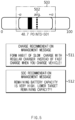
- FIG. 5 is a view for describing a response message referred in various embodiments disclosed herein.
- a response message including a stress score and a driving guide is shown.
- the controller 120 may display a calculated stress score 501 and display an average stress score avg 502 of the battery together.
- the controller 120 may display and propose a target stress score section 503 based on the average stress score.
- the controller 120 may calculate a value for temperature, charge current, discharge current, and/or SOC based on the data included in the obtained battery information and determine the driving guide based on the calculated result value and the stress score.
- FIG. 5 as an example of the driving guide, a charge recommendation management message 511 and an SOC recommendation management message 512 are shown.
- FIG. 6 is another view for describing a response message referred in various embodiments disclosed herein.
- FIG. 6 an example of a detailed message regarding a stress score is shown.
- the controller 120 may output a detailed page together with a stress score through a response message, when receiving a request for the stress score.
- the controller 120 may output the response message including the stress score when receiving the request for the stress score and output the detailed message when receiving an additional input for the stress score included in the output response message.
- the detailed message may include detailed information about analysis of a driving habit and a charge habit according to the stress score.
- FIG. 7 is a diagram schematically showing a battery management method according to an embodiment disclosed herein.
- each operation of the battery management method may be performed by the battery management apparatus 100.
- the battery management apparatus 100 a matter redundant to the foregoing matter described will be omitted or briefly described.
- a battery management method may include operation S100 of obtaining battery information, operation S200 of determining a data distribution, operation S300 of determining a matching probability, operation S400 of determining a score, and operation S500 of calculating a stress score.
- Operation S100 may be an operation of obtaining battery information of at least one of voltage, current, and temperature and may be performed by the data obtaining unit 110.
- the data obtaining unit 110 may obtain information related to a battery for which a stress score is to be calculated. According to an embodiment, the data obtaining unit 110 may obtain, from the BMS 50, the information related to the battery for which a stress score is to be calculated.
- the data obtaining unit 110 may obtain information about the battery from the BMS 50 in real time or according to a predetermined period. Alternatively, the data obtaining unit 110 may obtain the information when a preset event occurs. The present disclosure is not limited thereto.
- the data obtaining unit 110 may transmit a request for providing data to the BMS 50 or the user terminal 30.
- Operation S200 is an operation of determining a data distribution of the battery based on the battery information obtained in operation S 100, and may be performed by the controller 120.
- the controller 120 may determine the data distribution of the battery based on obtained battery information. Depending on an embodiment, the controller 120 may determine a type of information based on whether the obtained information of the battery is during-driving information or during-charge information. The controller 120 may determine at least one data corresponding to the determined type among the plurality of previously obtained experiment data as the target experiment data. For example, when the obtained information of the battery is determined to be the during-driving information as the type of the information, the controller 120 may determine, as target data, experimental data with the during-driving information as the type of the information among the plurality of previously obtained experiment data.
- the controller 120 determines the target experiment data based on the type of the information, the accuracy of calculation of the stress score may be improved.
- the controller 120 may determine the data distribution of the battery by calculating an area-specific frequency for the battery information.
- the area-specific frequency may mean a frequency of each of areas included in the battery information.
- the area-specific frequency may mean a frequency for each of a voltage area, a current area, and a temperature area.
- Operation S300 is an operation of determining a matching probability between a plurality of previously obtained target experiment data and a data distribution, and may be performed by the controller 120.
- the controller 120 may determine the match probability for each of the plurality of target experiment data, based on the area-specific frequency of the battery information and the area-specific frequency of each of the plurality of target experiment data.
- the controller 120 may determine, for each area, a similarity between a frequency of each experiment data with respect to a sum of frequencies of a plurality of target experiment data, and a frequency for battery information, and determine a matching probability based on the similarity.
- the controller 120 may sum one or more similarities calculated respectively for the plurality of target experiment data to determine the matching probability corresponding to each of the plurality of target experiment data.
- Operation S400 is an operation of determining a score for each of the plurality of target experiment data based on the battery information and may be performed by the controller 120.
- the controller 120 may determine a score for each of the plurality of target experiment data based on the obtained battery information. Depending on an embodiment, the controller 120 may determine a score for each of the plurality of target experiment data based on a preset experiment condition-specific table.
- the preset experiment condition-specific table may mean result data of a battery deterioration experiment performed in an environment limited by a specific condition.
- the experiment condition-specific table may mean a table regarding target experiment data corresponding to a battery deterioration experiment performed by adding a condition to at least one area among a temperature, a charge current, a discharge current, a minimum SOC, and a maximum SOC of a battery and a SOH with respect to the number of times of charge/discharge of the target experiment data.
- the controller 120 may generate a SOH profile according to a cycle by processing data obtained by a battery deterioration experiment performed in the limited environment.
- the cycle may mean a value obtained by considering charge/discharge of the battery as one period.
- 1 cycle may mean that the battery is charged and discharged once based on an SOC of 0 % and an SOC of 100 %.
- the controller 120 may determine a score for the number of times of charge/discharge in which a calculated SOH reaches a threshold value.
- the threshold value may be a set value corresponding to the battery or a user-set value.
- the controller 120 may input a cycle value corresponding to a point in which a SOH is a threshold value for each of a plurality of target experiment data, to an experiment condition-specific table.
- the controller 120 may determine a score for each of the plurality of target experiment data based on the input cycle.
- the controller 120 may determine a score by interpolating a value for each of the plurality of target experiment data based on standard conditions.
- the standard conditions may mean conditions that are criterions for evaluating experiment data.
- Operation S500 is an operation of calculating the stress score for the battery by calculating a score for each of the plurality of target experiment data and a corresponding matching probability and may be performed by the controller 120.
- the controller 120 may calculate the stress score for the battery by calculating a matching probability corresponding to the score for each of the plurality of target experiment data.
- the controller 120 may calculate a stress score by summing all values obtained by multiplying a score of each target experiment data by a matching probability for each of a plurality of target experiment data.
- the controller 120 may classify target experiment data having a matching probability equal to or greater than a threshold value among the plurality of target experiment data as a first group, and calculate a stress score by summing a product of a score corresponding to each target data included in the first group and a corresponding matching probability.
- the controller 120 may interpolate a matching probability value of the target data or adjust a threshold value for the matching probability, when the number of target experiment data included in the first group is less than the threshold value.
- the controller 120 may classify target experiment data having an area-specific similarity equal to or greater than a threshold value as a second group, and calculate a stress score by summing a product of a score corresponding to each target experiment data included in the second group and a corresponding matching probability.
- the controller 120 may interpolate an area-specific similarity value of the target data or adjust a threshold value for the similarity value, when the number of target experiment data included in the second group is less than the threshold value.
- the controller 120 may calculate the stress score for the first group as a first stress score and the stress score for the second group as a second stress score and provide them to the user.
- the controller 120 may satisfy various needs of the user.
- the battery management apparatus 100 may be included in a battery pack 1000. That is, the battery pack according to the present disclosure may include the above-described battery management apparatus 100 and one or more battery cells.
- the battery pack may further include an electrical component (a relay, a fuse, etc.), a case, and so forth.
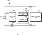
- FIG. 8 is a view showing an example configuration of a battery pack including a battery management apparatus according to an embodiment disclosed herein.
- a positive terminal of the battery 10 may be connected to a positive terminal P+ of the battery pack 1000, and a negative terminal of the battery 10 may be connected to a negative terminal P- of the battery pack 1000.
- a measuring unit 200 may be connected to a first sensing line SL1, a second sensing line SL2, and a third sensing line SL3. More specifically, the measuring unit 20 may be connected to the positive terminal of the battery 10 through the first sensing line SL1 and to the negative terminal of the battery 10 through the second sensing line SL2. The measuring unit 20 may measure a voltage of the battery 10 based on a voltage measured in each of the first sensing line SL1 and the second sensing line SL2.
- the measuring unit 200 may be connected to a current measuring unit A through the third sensing line SL3.
- the current measuring unit A may be an ammeter or a shunt resistor capable of measuring a charge current and a discharge current of the battery 10.
- the measuring unit 20 may measure a charge current of the battery 10 through the third sensing line SL3 to calculate the amount of charge.
- the measuring unit 200 may also measure the discharge current of the battery 10 through the third sensing line SL3 to calculate the amount of discharge.
- a terminal of a load 2 may be connected to the positive terminal P+ of the battery pack 1000, and the other end thereof may be connected to the negative terminal of the battery 1000.
- the positive terminal of the battery 10 the positive terminal P+ of the battery pack 1000, the load 2, the negative terminal P- of the battery pack 1000, and the negative terminal of the battery 10 may be electrically connected.
- the load 2 may be a charge/discharge device, and may be a motor of an electric vehicle provided with a power from the battery 10, etc.
- the data obtaining unit 110 may obtain battery information of at least one of voltage, current, and temperature from the measuring unit 200.
Landscapes
- Physics & Mathematics (AREA)
- General Physics & Mathematics (AREA)
- Charge And Discharge Circuits For Batteries Or The Like (AREA)
- Secondary Cells (AREA)
- Tests Of Electric Status Of Batteries (AREA)
Applications Claiming Priority (2)
| Application Number | Priority Date | Filing Date | Title |
|---|---|---|---|
| KR1020220042555A KR102936440B1 (ko) | 2022-04-05 | 2022-04-05 | 배터리 관리 장치 및 방법 |
| PCT/KR2022/018840 WO2023195592A1 (ko) | 2022-04-05 | 2022-11-25 | 배터리 관리 장치 및 방법 |
Publications (2)
| Publication Number | Publication Date |
|---|---|
| EP4502632A1 true EP4502632A1 (de) | 2025-02-05 |
| EP4502632A4 EP4502632A4 (de) | 2025-07-23 |
Family
ID=88242973
Family Applications (1)
| Application Number | Title | Priority Date | Filing Date |
|---|---|---|---|
| EP22936645.5A Pending EP4502632A4 (de) | 2022-04-05 | 2022-11-25 | Batterieverwaltungsvorrichtung und -verfahren |
Country Status (5)
| Country | Link |
|---|---|
| EP (1) | EP4502632A4 (de) |
| JP (1) | JP7786771B2 (de) |
| KR (1) | KR102936440B1 (de) |
| CN (1) | CN118984944A (de) |
| WO (1) | WO2023195592A1 (de) |
Families Citing this family (1)
| Publication number | Priority date | Publication date | Assignee | Title |
|---|---|---|---|---|
| WO2025244215A1 (ko) * | 2024-05-22 | 2025-11-27 | 주식회사 엘지에너지솔루션 | 전자 장치, 기록매체 및 그의 배터리 충전 패턴에 관한 데이터의 군집화 방법 |
Family Cites Families (13)
| Publication number | Priority date | Publication date | Assignee | Title |
|---|---|---|---|---|
| US20130069660A1 (en) | 2010-02-17 | 2013-03-21 | Julien Bernard | Method for in situ battery diagnostic by electrochemical impedance spectroscopy |
| PL2796887T3 (pl) | 2012-03-27 | 2020-05-18 | Lg Chem, Ltd. | Aparat do pomiaru rezystancji izolacji, mający funkcję autodiagnozowania usterek, oraz sposób autodiagnozowania usterek przy jego użyciu |
| JP2015135286A (ja) * | 2014-01-17 | 2015-07-27 | 株式会社豊田中央研究所 | 二次電池の特性推定装置 |
| KR102399720B1 (ko) * | 2014-08-06 | 2022-05-19 | 삼성전자주식회사 | 패턴 정보에 기초하여 사용자 특성에 따른 배터리 수명을 추정하는 장치 및 방법 |
| JP2017134894A (ja) | 2016-01-25 | 2017-08-03 | トヨタ自動車株式会社 | 二次電池の再利用方法 |
| CN109642930A (zh) | 2016-09-13 | 2019-04-16 | 松下知识产权经营株式会社 | 管理装置以及蓄电系统 |
| JP7253130B2 (ja) * | 2017-08-04 | 2023-04-06 | グローバル バッテリー ソリューションズ エルエルシー | 電池セルモニタリング制御システム |
| KR101995227B1 (ko) * | 2018-04-03 | 2019-07-02 | 한국전력공사 | 에너지 저장장치의 진단 장치 및 방법 |
| JP7298114B2 (ja) * | 2018-06-25 | 2023-06-27 | 株式会社Gsユアサ | 状態推定方法、及び状態推定装置 |
| EP3591414B1 (de) * | 2018-07-03 | 2022-01-19 | Electricité de France | Verfahren zur bewertung des gesundheitszustands einer elektrischen batterie |
| KR102949949B1 (ko) * | 2019-08-23 | 2026-04-08 | 주식회사 엘지에너지솔루션 | 배터리 soh 예측 방법 및 이를 적용한 배터리 팩 |
| KR102861117B1 (ko) * | 2020-06-11 | 2025-09-16 | 주식회사 엘지에너지솔루션 | 배터리 상태 진단 장치 및 방법 |
| KR102904406B1 (ko) * | 2020-07-21 | 2025-12-26 | 삼성전자주식회사 | 배터리 상태를 식별하기 위한 방법, 이를 위한 전자 장치 및 저장 매체 |
-
2022
- 2022-04-05 KR KR1020220042555A patent/KR102936440B1/ko active Active
- 2022-11-25 JP JP2024558986A patent/JP7786771B2/ja active Active
- 2022-11-25 EP EP22936645.5A patent/EP4502632A4/de active Pending
- 2022-11-25 CN CN202280094517.4A patent/CN118984944A/zh active Pending
- 2022-11-25 WO PCT/KR2022/018840 patent/WO2023195592A1/ko not_active Ceased
Also Published As
| Publication number | Publication date |
|---|---|
| KR102936440B1 (ko) | 2026-03-09 |
| WO2023195592A1 (ko) | 2023-10-12 |
| JP2025511369A (ja) | 2025-04-15 |
| JP7786771B2 (ja) | 2025-12-16 |
| EP4502632A4 (de) | 2025-07-23 |
| CN118984944A (zh) | 2024-11-19 |
| KR20230143525A (ko) | 2023-10-12 |
Similar Documents
| Publication | Publication Date | Title |
|---|---|---|
| US20250389775A1 (en) | Battery Management Apparatus and Method | |
| EP4148950A2 (de) | Batterieverwaltungsvorrichtung und -verfahren | |
| EP4198536A1 (de) | Batterieverwaltungsvorrichtung und -verfahren | |
| EP4498103A1 (de) | Batterieverwaltungsvorrichtung und -verfahren | |
| EP3992649B1 (de) | Vorrichtung und verfahren zur einstellung von batterieparametern | |
| EP4145589A1 (de) | Batterieklassifizierungsvorrichtung und -verfahren | |
| EP4446760A1 (de) | Vorrichtung zur berechnung der ladetiefe einer batterie und betriebsverfahren dafür | |
| KR20220159818A (ko) | 배터리 모니터링 장치 및 방법 | |
| CN115667957B (zh) | 电池管理设备、电池检测装置及电池管理方法 | |
| EP4632400A1 (de) | Vorrichtung zur vorhersage der in einer batterie erzeugten gasmenge und betriebsverfahren dafür | |
| EP4382935B1 (de) | Batterieverwaltungsvorrichtung und -verfahren | |
| EP4502632A1 (de) | Batterieverwaltungsvorrichtung und -verfahren | |
| EP4152025A1 (de) | Batteriediagnosevorrichtung und -verfahren | |
| EP4575538A1 (de) | System und verfahren zur diagnose des verschlechterungszustands einer batterie | |
| EP4653897A1 (de) | Batteriediagnosevorrichtung und betriebsverfahren dafür | |
| EP4462140B1 (de) | Vorrichtung und verfahren zur schätzung von batterieparametern | |
| EP4635790A1 (de) | Vorrichtung zur bereitstellung von batterielebensdauerinformationen und betriebsverfahren dafür | |
| EP4385803A1 (de) | Vorrichtung und verfahren zur paarung von batterien | |
| EP4734324A1 (de) | Ladeverwaltungsvorrichtung und betriebsverfahren dafür | |
| EP4675292A1 (de) | Batteriediagnosevorrichtung und betriebsverfahren dafür | |
| EP4697046A1 (de) | Batteriediagnosevorrichtung und betriebsverfahren dafür | |
| EP4697043A1 (de) | Batteriediagnosevorrichtung und betriebsverfahren dafür | |
| US20250085358A1 (en) | Information processing device, information processing method, computer program product, and information processing system | |
| KR20240033678A (ko) | 배터리 페어링 장치 및 방법 | |
| KR20260053748A (ko) | 배터리 진단 장치 및 방법 |
Legal Events
| Date | Code | Title | Description |
|---|---|---|---|
| STAA | Information on the status of an ep patent application or granted ep patent |
Free format text: STATUS: THE INTERNATIONAL PUBLICATION HAS BEEN MADE |
|
| PUAI | Public reference made under article 153(3) epc to a published international application that has entered the european phase |
Free format text: ORIGINAL CODE: 0009012 |
|
| STAA | Information on the status of an ep patent application or granted ep patent |
Free format text: STATUS: REQUEST FOR EXAMINATION WAS MADE |
|
| 17P | Request for examination filed |
Effective date: 20241029 |
|
| AK | Designated contracting states |
Kind code of ref document: A1 Designated state(s): AL AT BE BG CH CY CZ DE DK EE ES FI FR GB GR HR HU IE IS IT LI LT LU LV MC ME MK MT NL NO PL PT RO RS SE SI SK SM TR |
|
| DAV | Request for validation of the european patent (deleted) | ||
| DAX | Request for extension of the european patent (deleted) | ||
| A4 | Supplementary search report drawn up and despatched |
Effective date: 20250623 |
|
| RIC1 | Information provided on ipc code assigned before grant |
Ipc: G01R 31/367 20190101AFI20250616BHEP Ipc: G01R 31/392 20190101ALI20250616BHEP Ipc: G01R 31/382 20190101ALI20250616BHEP Ipc: G01R 31/36 20200101ALI20250616BHEP |
|
| STAA | Information on the status of an ep patent application or granted ep patent |
Free format text: STATUS: EXAMINATION IS IN PROGRESS |
|
| 17Q | First examination report despatched |
Effective date: 20251117 |